

Cisco. Fundamentals Network Design - Cisco Press
.pdfDialer Maps
Checks against dialer map statements for broadcasts will fail because a broadcast packet is transmitted with a next-hop address of the broadcast address. If you want broadcast packets transmitted to remote sites defined by dialer map statements, use the broadcast keyword with the dialer map command.
To configure whether calls are placed at 56 or 64 Kbps for ISDN calls, you can use the speed option with the dialer map command when configuring interfaces. See Chapter 11, “Designing ISDN Internetworks,” for details on ISDN media.
When setting up DDR between more than two sites, it is necessary to use PPP authentication and to use the name keyword with the dialer map command, as dialer maps for inbound calls are maps between protocol addresses and authenticated user names.
To facilitate building of dialer maps, the internetwork designer should build an Address Mapping Table as an aid for configuration. In Table 10-2, the dialer cloud has been assigned IP subnet 172.20.1.0/24, IPX network 100, and AppleTalk cable-range 20-20. Table 10-2 forms the basis for building proper dialer maps for each site.
Table 10-2 |
DDR Address Mapping Table for KDT |
|
|
|
|
|
|
Remote Site |
Dial-In Protocols |
Directory# |
Notes |
|
|
|
|
c700A |
IP: 172.20.1.2 |
4085551212 |
|
|
IPX: 100.0000.0c00.0002 |
|
|
|
|
|
|
c700B |
IP:172.20.1.3 |
4155558888 |
56K |
|
|
|
|
c1600A |
IP: 172.20.1.4 |
5305551000 |
|
|
AT: 20.4 |
|
|
|
|
|
|
c2500A |
IP: 172.20.1.5 |
5125558085 |
|
|
IPX: 100.0000.0c00.0005 |
|
|
|
AT: 20.5 |
|
|
|
|
|
|
c2500B |
IP: 172.20.1.6 |
2105552020 |
|
|
IPX: 100.0000.0c00.0006 |
|
|
|
|
|
|
NAS3600A |
IP: 172.20.1.1 |
8355558661 |
Hub |
|
IPX: 100.0000.0c00.0001 |
|
|
|
|
|
|
As NAS3600A forms the hub in the hub-and-spoke topology, each remote site is configured with the dialer maps to get to the central site. For example, the dialer map configuration for c1600A would be as follows:
interface dialer1 encapsulation ppp
ip address 172.20.1.4 255.255.255.0 appletalk cable-range 20-20 20.4 appletalk zone ZZ DDR
dialer in-band
dialer map ip 172.20.1.1 name nas3600A speed 56 18355558661 dialer map appletalk 20.1 name nas3600A speed 56 18355558661 dialer-group 5
ppp authentication chap callin
Designing DDR Internetworks 10-9

Routing Strategies
The dialer map configuration for NAS3600A would be as follows:
interface dialer1 encapsulation ppp
ip address 172.20.1.1 255.255.255.0 appletalk cable-range 20-20 20.1 appletalk zone ZZ DDR
ipx network 100 dialer in-band
dialer map ip 172.20.1.2 name c700A dialer map ipx 100.0000.0c00.0002 c700A dialer map ip 172.20.1.3 name c700B
dialer map ip 172.20.1.4 name speed 56 c1600A 15305551000 dialer map appletalk 20.4 name c1600A
dialer map ip 172.20.1.5 name c2500A 15125558085
dialer map ipx 100.0000.0c00.0005 name c2500A 15125558085 dialer map appletalk 20.5 name c2500A 15125558085
dialer map ip 172.20.1.6 name c2500B 12105552020 dialer map ipx 100.0000.0c00.0006 name c2500B dialer-group 5
ppp authentication chap callin
Note that dialer maps provide mapping between remote site protocol addresses, remote site names, and remote site directory numbers. For dial-in only sites, directory numbers are not required and can be left off to avoid inadvertent dialing. Table was used to determine which sites do not require dial-out support. For dial-in sites, the ppp authentication name is mapped to the protocol address to ensure outbound packets are placed on the correct PPP connection.
Recent Cisco IOS releases can build dynamic dialer maps using for IP (using IPCP address negotiation) and IPX (using IPXCP address negotiation), eliminating the need for dialer maps for dial-in only sites.
The DDR designer should familiarize themselves with the use of the Cisco IOS exec commands show dialer and show dialer map to examine the state of the DDR sites, the physical interfaces, and the dialer map table. Use debug dialer to troubleshoot DDR connection problems.
c1600A#sh dialer |
|
|
|
|
|
BRI0 |
- dialer type = ISDN |
|
|
|
|
Dial |
String |
Successes |
Failures |
Last called |
Last status |
1835558661 0 |
0 |
never |
- |
|
|
0 incoming call(s) have been screened. BRI0:1 - dialer type = ISDN
Idle timer (60 secs), Fast idle timer (20 secs) Wait for carrier (30 secs), Re-enable (5 secs) Dialer state is idle
BRI0:2 - dialer type = ISDN
Idle timer (60 secs), Fast idle timer (20 secs) Wait for carrier (30 secs), Re-enable (5 secs) Dialer state is idle
c1600A#sh dialer map
Static dialer map ip 172.20.1.4 name nas (8355558661) on BRI0
Routing Strategies
The nature of DDR networks is that routing and some directory services tables must be maintained over idle connections. DDR designers may use a combination of static, dynamic, and snapshot routing techniques to meet design needs. Default routing and remote node spoofing techniques (such as Cisco 700 Series PAT and Cisco IOS EZIP) can be used to greatly simplify routing design.
10-10 Cisco CCIE Fundamentals: Network Design

Static Routing
Often the backbone at the NAS site will use a fast-converging routing protocol such as OSPF or EIGRP; however, these protocols do not operate easily on the dialer media due to their broadcast and link-state nature. Typically, static routing and/or distance vector routing protocols are selected for the DDR connections. Routing redistribution may be required to support propagation of routing information between the different routing protocols.
A complete discussion of routing redistribution techniques is beyond the scope of this chapter; however, DDR designers do need to develop and verify their routing strategy for each network protocol.
Static Routing
With static routes, network protocol routes are entered manually, eliminating the need for a routing protocol to broadcast routing updates across the DDR connection. Static routes can be effective in small networks that do not change often. Routing protocols can generate traffic that causes connections to be made unnecessarily.
When designing with IP unnumbered environments, older versions of Cisco IOS required multiple static routes for each site: one route to define the next-hop IP address and a second to define the interface on which to find the next-hop (and dialer map). The following code:
interface Dialer1
ip unnumbered Ethernet0/0 dialer in-band
dialer map ip 172.17.1.100 name kdt-NAS speed 56 5558660 dialer-group 5
!
ip classless
ip route 0.0.0.0 0.0.0.0 172.17.1.100 200
ip route 172.17.1.100 255.255.255.255 Dialer1 200 dialer-list 5 protocol ip permit
creates the following routing table:
kdt-3640#sh ip route
...<snip>...
Gateway of last resort is 172.17.1.100 to network 0.0.0.0 172.17.0.0/32 is subnetted, 1 subnets
S |
172.17.1.100 is directly |
connected, Dialer1 |
|
172.20.0.0/24 is subnetted, |
1 subnets |
S* |
0.0.0.0/0 [200/0] via 172.17.1.100 |
|
Recent Cisco IOS versions allow configuration of this as one route. For example, the example configuration here:
ip route 0.0.0.0 0.0.0.0 Dialer1 172.17.1.100 200 permanent
results in a simplified routing table, as follows:
kdt-3640#sh ip route
...<snip>...
Gateway of last resort is 172.17.1.100 to network 0.0.0.0 172.20.0.0/24 is subnetted, 1 subnets
C |
172.20.1.0 is directly connected, Ethernet0/0 |
S* |
0.0.0.0/0 [200/0] via 172.17.1.100, Dialer1 |
It is typically necessary to configure redistribution of static routes into the backbone dynamic routing protocol to ensure end-to-end connectivity. For example, to redistribute the static route to other networks in IGRP autonomous system 20, use the following configuration commands:
router igrp 20 network 172.20.0.0 redistribute static
Designing DDR Internetworks 10-11

Routing Strategies
Dynamic Routing
Dynamic routing can be used in DDR network design in a number of ways. Dynamic routing can be used with snapshot routing (as described in the “Snapshot Routing” section later in this chapter) to cache routes learned by dynamic routing protocols, thus allowing the automation of static routing maintenance. Dynamic routing can be used as a trigger for routing convergence in large and complex DDR designs.
When the DDR link is connected, routing updates will flow to the peer, allowing redundant designs to converge on the physical connection by redistribution of trigger routing updates.
Selecting a Dynamic Routing Protocol
The routing protocol selected for DDR link is typical of a Distance Vector protocol such as RIP, RIP II, EIGRP, IGRP, or RTMP. Selecting the simplest protocol that meets the needs of the internetwork design and that is supported by the DDR routers is recommended.
Passive Interfaces
Interfaces that are tagged as passive will not send routing updates. To prevent routing updates from establishing DDR connections on dialer interfaces that do not rely on dynamic routing information, configure DDR interfaces with the passive-interface command or use access lists as described in the section “IPX Access Lists” later in this chapter. Using either the passive-interface command or an access list prevents routing updates from triggering a call. However, if you want routing updates to be passed when the link is active, use an access list rather than the passive-interface command.
Split Horizons
Routers connected to broadcast-type IP networks and routers that use distance-vector routing protocols use split horizons to reduce the possibility of routing loops. When split horizons are enabled, information about routes that comes in on an interface is not advertised out on that same interface.
Note If remote sites need to communicate with one another, split horizons should be disabled for hub-and-spoke topologies. In hub-and-spoke topologies, spokes learn about one another through the hub site to which they are connected by a single interface. In order for spokes to send and receive information to one another, split horizons may need to be disabled so that full routing tables are built at each site.
Dynamic Connected Routes
Dynamic connected routes include the two following:
•Per-user AAA Installed Routes— AAA servers can install routes associated with users by using AAA authorization to download and install routes as remote sites connect.
•PPP Peer Routes—IPCP address negotiation installs host-routes (/32 subnet mask) for the remote peer. This host-route can be propagated to backbone routers to provide robust routing convergence. In most applications, the peer host-route will be beneficial (or innocuous) to the internetwork design. If PPP peer host-routes interact poorly with existing routing strategies, they can be turned off with the interface configuration command no peer neighbor-route.
10-12 Cisco CCIE Fundamentals: Network Design

Snapshot Routing
Snapshot Routing
With snapshot routing, the router is configured for dynamic routing. Snapshot routing controls the update interval of the routing protocols. Snapshot routing works with the following distance vector protocols:
•
•
•
•
•
Routing Information Protocol (RIP) for IP
Interior Gateway Routing Protocol (IGRP) for IP
Routing Information Protocol (RIP) and Service Advertisement Protocol (SAP) for Novell Internet Packet Exchange (IPX)
Routing Table Maintenance Protocol (RTMP) for AppleTalk
Routing Table Protocol (RTP) for Banyan VINES
Under normal circumstances, these routing protocols broadcast updates every 10 to 60 seconds, so an ISDN link would be made every 10 to 60 seconds simply to exchange routing information. From a cost perspective, this frequency is prohibitive. Snapshot routing solves this problem.
Note Snapshot routing is available in Cisco IOS Software Release 10.2 or later.
Snapshot Model
Snapshot routing uses the client-server design model. When snapshot routing is configured, one router is designated as the snapshot server and one or more routers are designated as snapshot clients. The server and clients exchange routing information during an active period. At the beginning of the active period, the client router dials the server router to exchange routing information. At the end of the active period, each router takes a snapshot of the entries in its routing table. These entries remain frozen during a quiet period. At the end of the quiet period, another active period begins, and the client router dials the server router to obtain the latest routing information. The client router determines the frequency at which it calls the server router. The quiet period can be as long as 100,000 minutes (approximately 69 days).
When the client router transitions from the quiet period to the active period, the line might be down or busy. If this happens, the router would have to wait through another entire quiet period before it could update its routing table, which might severely affect connectivity if the quiet period is very long. To avoid having to wait through the quiet period, snapshot routing supports a retry period. If the line is not available when the quiet period ends, the router waits for the amount of time specified by the retry period and then transitions to an active period once again.
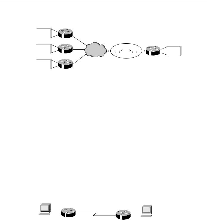
The retry period is also useful in dial-up environments in which there are more remote sites than interface lines. For example, the central site might have one PRI (with 23 B channels available) but might dial more than 23 remote sites. In this situation, there are more dialer map commands than available lines. The router tries the dialer map commands in order and uses the retry time for the lines that it cannot immediately access (see Figure 10-5).
Designing DDR Internetworks 10-13
Routing Strategies
Figure 10-5 |
Snapshot routers in action. |
|
|
|
|
|
|
|
|
|
|
|
||||
Slave Routers |
|
|
|
|
|
|
|
|
|
|
|
|
|
|
||
|
|
|
|
|
|
|
|
|
|
|
|
|
|
|
|
|
Routing |
|
|
|
|
|
|
|
|
|
|
|
|
|
|
|
|
|
|
|
|
|
|
|
|
|
|
|
|
|
|
|
|
|
Table |
|
|
|
|
|
|
|
|
|
|
|
|
|
|
|
|
|
|
|
|
|
|
|
|
|
|
|
|
|
|
Master Router |
||
|
|
|
|
|
|
|
|
|
|
|
|
|
|
|
|
|
Routing |
|
|
|
|
|
|
|
T2 |
|
|
|
|
|
|
|
|
Table |
|
|
|
ISDN |
|
T1 |
|
T1 |
|
|
|
|
Routing |
|
||
|
|
|
|
|
|
|
|
|
|
|
|
|||||
|
|
|
|
|
|
|
|
|
|
|
|
|
|
Table |
|
|
|
|
|
|
|
|
|
|
|
|
|
|
|
|
|
|
|
|
|
|
|
|
|
|
|
Time |
|
|
|
|
|
|||
|
|
|
|
|
|
|
|
|
|
|
|
|
|
|||
|
|
|
|
|
|
|
|
|
|
|
|
|
|
|
|
|
Routing |
|
|
|
|
|
|
|
|
|
|
|
|
|
|
|
|
|
|
|
|
|
|
|
|
|
|
|
|
|
|
|
|
|
Table |
|
|
|
|
|
|
|
|
|
|
|
|
|
|
|
|
|
|
|
|
|
|
|
|
|
|
|
|
|
|
|
|
|
Enabling Snapshot Routing
Snapshot routing is enabled through interface configuration commands (see Figure 10-6). The central router is configured for snapshot routing by applying the snapshot server interface configuration command to its ISDN interfaces. The snapshot server command specifies the length of the active period and whether the router is allowed to dial remote sites to exchange routing updates in the absence of regular traffic.
The remote routers are configured for snapshot routing by applying the snapshot client command to each ISDN interface. The snapshot client interface configuration command specifies the following variables:
•The length of the active period (which must match the length specified on the central router)
•The length of the quiet period
•Whether the router can dial the central router to exchange routing updates in the absence of regular traffic
•Whether connections that are established to exchange user data can be used to exchange routing updates
When the backbone routing protocol is not supported by snapshot routing (for example, OSPF or EIGRP), standard routing redistribution techniques can be used to ensure that routing updates are propagated between routing protocols, as required. Care should be taken to ensure redistribution of subnets if needed and to avoid routing loops.
Figure 10-6 |
AppleTalk snapshot routing. |
|
|
|
|
|
|
|
||||||||
|
|
|
|
|
|
|
R1 |
|
Zone: WAN |
|
R2 |
|
|
|
|
|
|
|
|
|
|
|
|
|
|
|
|
|
|||||
|
|
|
|
|
|
|
|
|
|
|
|
|
|
|||
|
|
|
|
|
|
|
|
|
Cable-range: 700-700 |
|
|
|
|
|
||
|
|
|
|
|
E0 |
|
|
|
|
|
|
|
|
|
|
|
|
|
|
|
|
|
|
|
|
B0 |
|
|
E0 |
|
|
|
|
|
|
|
|
|
|
|
|
|
|
|
|
|
|
|||
|
|
|
|
|
|
|
|
|
B0 |
|
|
|
|
|
|
|
|
|
|
|
|
|
|
|
|
|
|
|
|
|
|
||
|
|
|
|
|
|
|
|
|
|
|
|
|
|
|
|
|
|
|
|
|
|
|
|
|
|
|
|
|
|
|
|
|
|
|
|
|
|
|
|
|
|
|
|
|
|
|
|
|
|
|
|
|
Zone: HQ |
|
|
|
|
|
|
Zone: Branch |
|||||||
Cable-range: 101-200 |
|
|
Cable-range: 201-300 |
|||||||||||||
10-14 Cisco CCIE Fundamentals: Network Design

Dial Backup for Leased Lines
• R1 configuration is as follows:
username R2 password SECRET appletalk routing
isdn switch-type basic-5ess
!
interface BRI0 encapsulation ppp
appletalk cable-range 700-700 700.1 appletalk zone WAN
dialer map appletalk 700.2 name R2 speed 56 broadcast 5552222 dialer map snapshot 2 name R2 speed 56 broadcast 5552222 dialer-group 1
snapshot client 5 60 dialer isdn spid1 5550066
ppp authentication chap
!
dialer-list 1 protocol appletalk permit
• R2 configuration is as follows:
username R1 password SECRET appletalk routing
isdn switch-type basic-5ess interface BRI0 encapsulation ppp
appletalk cable-range 700-700 700.2 appletalk zone WAN
dialer wait-for-carrier-time 60
dialer map appletalk 700.1 name R1 speed 56 broadcast 5550066 dialer-group 1
snapshot server 5 dialer isdn spid1 5552222
ppp authentication chap
!
dialer-list 1 protocol appletalk permit
For a further examination of snapshot routing, see Chapter 21, “Using ISDN Effectively in Multiprotocol Networks.”
Dial Backup for Leased Lines
Dial backup protects against wide-area network (WAN) downtime by allowing a dedicated serial connection to be backed up by a circuit-switched connection. Dial backup can be performed in several ways: either with floating static routes or with backup interfaces.
Dial backup challenges the designer with different traffic patterns than DDR-supported SOHO and ROBO sites. When designing Dial backup port densities, consider how many links might fail concurrently in a mass-failure scenario, as well as how many ports will be required on the central site in a worst-case scenario. Typical design involves selecting only dial-in or dial-out to avoid contention when both sides are trying to re-establish connectivity.
Backup Interfaces
A primary/dedicated serial line is configured to have a backup interface in the event of link failure or exceeded load thresholds. If the interface line or line protocol state goes down, the backup interface is used to establish a connection to the remote site.
Once configured, the dial backup interface remains inactive until one of the following conditions is met:
1Line Protocol on the primary link goes down. The backup line is then activated, re-establishing the connection between the two sites.
Designing DDR Internetworks 10-15
Routing Strategies
2The traffic load on the primary line exceeds a defined limit—The traffic load is monitored and a five-minute moving average is computed. If the average exceeds the user-defined value for the line, the backup line is activated. Depending on how the backup line is configured, some or all of the traffic flows onto it.
A Cisco IOS interface is placed into backup mode by applying the backup interface command:
•The backup interface interface configuration command specifies the interface that is to act as the backup.
•The backup load command specifies the traffic threshold at which the backup interface is to be activated and deactivated.
•The backup delay command specifies the amount of time that is to elapse before the backup interface is activated or deactivated after a transition on the primary interface.
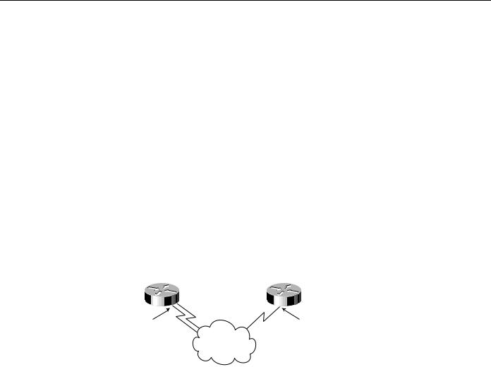
Backup interfaces traditionally lock the backup interface into BACKUP state so it is unavailable for other use. Dialer Profiles eliminates this lock and allows the physical interface to be used for multiple purposes. Floating Static Route DDR design also eliminates this lock on the dialer interface. In Figure 10-7, a leased line connects Router A to Router B, and BRI 0 on Router B is used as a backup line.
Figure 10-7 Example of dial backup over ISDN.
171 69 158 18 |
|
|
|
|
|
|
|
|
|
171 69 159 49 |
||
255 255 255 248 |
|
Router |
|
A |
|
Router |
|
B |
|
255 255 255 249 |
||
|
|
|
|
|
||||||||
|
|
|
|
|
|
|
|
|
||||
|
E0 |
|
|
|
|
|
E0 |
|||||
171 69 159 25 |
|
|
171 |
69 159 26 |
|
|||||||
255 255 255 249 |
|
|
255 |
255 255 249 |
|
|||||||
ISDN
Using the configuration that follows, BRI 0 is activated only when serial interface 1/0 (the primary line) goes down. The backup delay command configures the backup connection to activate 30 seconds after serial interface 0 goes down and to remain activated for 60 seconds after the serial interface 1/0 comes up:
interface serial 1/0
ip address 172.20.1.4 255.255.255.0 backup interface bri 2/0
backup delay 30 60
Using the configuration that follows, BRI 2/0 is activated only when the load on serial 0 (the primary line) exceeds 75 percent of its bandwidth. The backup line is deactivated when the aggregate load between the primary and backup lines is within five percent of the primary line’s bandwidth:
interface serial 1/0
ip address 172.20.1.4 255.255.255.0 backup interface bri 2/0
backup load 75 5
Using the following configuration, BRI 2/0 is activated only when serial interface 1/00 goes down or when traffic exceeds 25 percent. If serial interface 1/0 goes down, 10 seconds will elapse before BRI 0 becomes active. When serial interface 1/0 comes up, BRI 2/0 will remain active for 60
10-16 Cisco CCIE Fundamentals: Network Design

Dialer Filtering
seconds. If BRI 2/0 is activated by the load-threshold on serial interface 1/0, BRI 2/0 is deactivated when the aggregate load of serial interface 1/0 and BRI 2/0 returns to within five percent of the bandwidth of serial interface 1/0:
interface serial 1/0
ip address 172.20.1.4 255.255.255.0 backup interface bri 2/0
backup load 25 5 backup delay 10 60
Floating Static Routes
Backup interface operation is determined by the state of the line and line protocol on the primary link. It is possible that end-to-end connectivity is lost, but line protocol stays up. For example, line protocol on a FrameRelay link is determined by the status of ILMI messages between the FrameRelay DCE (switch). Connectivity to the Frame Relay DCE does not guarantee end-to-end connectivity.
Designing Dial Backup with floating static routes utilizes Cisco IOS routing table maintenance and dynamic routing protocols. See Chapter 15, “Dial-on-Demand Routing,” for examples of using Floating Static Routes to provide backup to leased lines.
IPX Static Routes and SAP Updates
With DDR, you need to configure static routes because routing updates are not received across inactive DDR connections. To create static routes to specified destinations, use the ipx route command. You can also configure static Service Advertisement Protocol (SAP) updates with the ipx sap command so that clients can always find a particular server. In this way, you can determine the areas on your internetwork where SAP updates will establish DDR connections.
In the following example, traffic to network 50 will always be sent to address 45.0000.0c07.00d3.
Traffic to network 75 will always be sent to address 45.0000.0c07.00de. The router will respond to
GNS queries with the server WALT if there are no dynamic SAPs available:
ipx route 50 45.0000.0c07.00d3 ipx route 75 45.0000.0c07.00de
ipx sap 4 WALT 451 75.0000.0000.0001 15
Configuring AppleTalk Static Zones
Static AppleTalk routes and zones are created using the appletalk static command as in the following example:
appletalk static cable-range 110-110 to 45.2 zone Marketing
In many cases, manual configuration of static appletalk cable-ranges and zones will prove to be onerous. Snapshot routing should be investigated to provide automated route caching.
Dialer Filtering
Dialer filtering (see Figure 10-8) is used to classify all packets traversing the DDR connection as either interesting or uninteresting using Access Control Lists (ACLs). Only interesting packets can bring up and keep up DDR connections. It is the task of the DDR designer to determine which kinds of packets are to be deemed uninteresting and develop ACLs to prevent these uninteresting packets from causing unnecessary DDR connections.
Designing DDR Internetworks 10-17

Dialer Filtering
If a packet is uninteresting and there is no connection established, the packet is dropped. If the packet is uninteresting, but a connection is already established to the specified destination, the packet is sent across the connection, but the idle timer is not reset. If the packet is interesting, and there is no connection on the available interface, the router attempts to establish a connection.
Figure 10-8 |
Dialer filtering. |
|
|
|
|
|
|
|
|
|||||||
|
|
|
|
|
|
|
Dialer Filtering |
|
|
|
|
|||||
To |
Dialer |
Interesting |
No |
|
|
|
|
|
|
|
|
|||||
|
|
|
|
|
|
|
|
|
|
|||||||
|
|
|
|
|
Yes |
|
|
|
|
|
|
|
|
|||
|
|
|
Yes |
|
|
|
|
|
|
|
|
|
|
|
|
|
|
|
|
|
|
No |
|
|
|
No |
|
|
No |
||||
|
|
|
|
|
|
|
|
|
|
|||||||
|
|
|
|
|
|
|
|
|
||||||||
|
|
|
|
|
|
Connected |
|
Phone |
# |
|
|
|
Connected |
|||
|
|
|
|
|
|
|
Yes |
|
|
|
|
|
Yes |
|||
|
|
|
|
|
|
|
|
|
|
|
|
|
||||
|
|
|
|
|
|
|
|
|
|
|
|
|
||||
|
|
|
|
|
|
|
|
|
||||||||
|
Reset Idle |
|
|
|
|
|
|
|
|
|
|
|
|
|
||
|
|
|
|
|
|
Dial |
|
|
|
|
|
|||||
|
|
Timer |
|
|
|
|
|
|
|
|
|
|
||||
|
|
|
|
|
|
|
|
|
|
|
|
|
|
|
|
|
|
|
|
|
|
|
|
|
|
|
|
|
|
|
|
|
|
|
|
|
|
|
|
|
|
|
|
|
|
|
|
|
|
|
Send
Each packet arriving at a dialer interface is filtered and determined to be interesting or uninteresting based on dialer-group and dialer-list configuration. The following Cisco IOS configuration interface dialer 1 uses dialer-group 5 to determine interesting packets, as defined by the dialer-list 5 commands. Dialer-group 5 is defined by dialer-list 5 commands which in this case deems all IP, IPX, and AppleTalk packets to be interesting.
interface Dialer1 dialer-group 5
!
dialer-list 5 protocol ip permit dialer-list 5 protocol ipx permit dialer-list 5 protocol appletalk permit
!
Cisco IOS now supports many dialer-filtering protocols, as seen by the dialer-list online help:
kdt-3640(config)#dialer-list 5 protocol ?
appletalk |
AppleTalk |
bridge |
Bridging |
clns |
OSI Connectionless Network Service |
clns_es |
CLNS End System |
clns_is |
CLNS Intermediate System |
decnet |
DECnet |
decnet_node |
DECnet node |
decnet_router-L1 |
DECnet router L1 |
decnet_router-L2 |
DECnet router L2 |
ip |
IP |
ipx |
Novell IPX |
llc2 |
LLC2 |
vines |
Banyan Vines |
xns |
XNS |
10-18 Cisco CCIE Fundamentals: Network Design