

Cisco. Fundamentals Network Design - Cisco Press
.pdfLANE Implementation
While waiting for LE_ARP resolution, the LEC forwards unicasts to the BUS. With LE_ARP resolution, a new “optimal” path becomes available. If the LEC switches immediately to the new path, it runs the risk of packets arriving out of order. To guard against this situation, the LANE standard provides a flush packet.
When the Data Direct VCC becomes available, the LEC generates a flush packet and sends it to the BUS. When the LEC receives its own flush packet on the Multicast Forward VCC, it knows that all previously sent unicasts must have already been forwarded. It is now safe to begin using the Data Direct VCC. Figure 8-16 shows an example of a fully connected ELAN.
Figure 8-16 Fully connected ELAN.
AIP Subinterfaces
LES BUS
Client Direct VCC
(Bidirectional)
LANE Implementation
As Table 8-3 indicates, the LANE functionality (the LECS, LEC, LES, and BUS) can be implemented in different Cisco devices.
Table 8-3 |
Cisco LANE Implementation |
|
|
|
|
|
|
|
|
Available LANE |
|
Cisco Product |
|
Components |
Required Software Release |
|
|
|
|
Family of Catalyst 5000 switches |
LECS, LES, BUS, LEC |
ATM Module Software Version 2.0 or later |
|
|
|
|
|
Family of Catalyst 3000 switches |
LECS, LES, BUS, LEC |
ATM Module Software Version 2.1 or later |
|
|
|
|
|
Family of Cisco 7000 routers |
LECS, LES, BUS, LEC |
Cisco IOS Software Release 11.0 or later |
|
|
|
|
|
Family of Cisco 7500 routers |
LECS, LES, BUS, LEC |
Cisco IOS Software Release 11.1 or later |
|
|
|
|
|
Family of Cisco 4500 and 4000 routers |
LECS, LES, BUS, LEC |
Cisco IOS Software Release 11.1 or later |
|
|
|
|
|
These functions will be defined on ATM physical interfaces and subinterfaces. A subinterface can be defined as a logical interface and is a part of a physical interface such as an Optical Carrier 3 (OC-3) fiber. ATM interfaces on the Cisco routers and the ATM module on the Catalyst 5000 switch can be logically divided into up to 255 logical subinterfaces. On the Catalyst 3000 switch, although the same Cisco IOS Software code is used, the subinterface concept does not apply. The LEC can be configured using the menu-driven interface.
Designing ATM Internetworks 8-21

LANE Implementation
This section examines the implementation of ATM LANE networks and covers the following topics:
•
•
LANE Design Considerations
LANE Redundancy
LANE Design Considerations
The following are some general LANE design considerations:
•The AIP provides an interface to ATM switching fabrics for transmitting and receiving data at rates of up to 155 Mbps bidirectionally. The actual rate is determined by the Physical layer interface module (PLIM).
•One active LECS supports all ELANs.
•In each ELAN, there is one LES/BUS pair and some number of LECs.
•The LES and BUS functionality must be defined on the same subinterface and cannot be separated.
•There can be only one active LES/BUS pair per subinterface.
•There can be only one LES/BUS pair per ELAN.
•The current LANE Phase 1 standard does not provide for any LES/BUS redundancy.
•The LECS and LES/BUS can be different routers, bridges, or workstations.
•VCCs can be either switched virtual circuits (SVCs) or permanent virtual circuits (PVCs), although PVC design configuration and complexity might make anything more than a very small network prohibitively unmanageable and complex.
•When defining VLANs with the Catalyst 5000 switch, each VLAN should be assigned to a different ELAN. The LES/BUS pair for each ELAN can reside on any of the following:
—Different subinterfaces on the same AIP
—Different AIPs in the same router
—Different AIPs in different routers
•There can be only one LEC per subinterface. If a LEC and a LES/BUS pair share a subinterface, they are (by definition) in the same ELAN.
•If a LEC on a router subinterface is assigned an IP, IPX, or AppleTalk address, that protocol is routable over that LEC. If there are multiple LECs on a router and they are assigned protocol addresses, routing will occur between the ELANs. For routing between ELANs to function correctly, an ELAN should be in only one subnet for a particular protocol.
PNNI in LANE Networks
Network designers can deploy PNNI as a Layer 2 routing protocol for bandwidth management, traffic distribution, and path redundancy for LANE networks. PNNI is an ATM routing protocol used for routing call setups and is implemented in the ATM switches. Most LANE networks consist of multiple ATM switches and typically employ the PNNI protocol.
Note Although PNNI is an advanced routing protocol and supports QoS-based routing, this particular aspect of PNNI is not discussed in this chapter because most LANE networks are based on the best-effort traffic category.
8-22 Cisco CCIE Fundamentals: Network Design
LANE Design Considerations
The LightStream 1010 ATM switch supports some PNNI-related features that can be useful in scaling LANE networks:
•To load balance call setup requests across multiple paths between two end stations
•To load balance call setups across multiple parallel links
•To support link and path redundancy with fast convergence
•To provide excellent call setup performance across multiple hops using the background routing feature
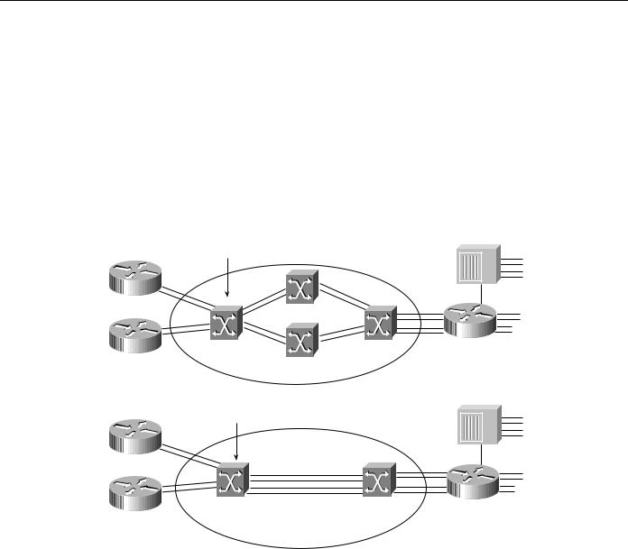
Figure 8-17 shows how the LightStream 1010 switch supports load balancing.
Figure 8-17 Load balancing calls across multiple paths and multiple links.
Call setups are load balanced across multiple paths
LEC |
|
|
|
LightStream |
LEC |
LEC |
1010 |
ATM Core |
|
|
Call setups are load balanced across parallel links
LEC |
|
|
|
LightStream |
LEC |
LEC |
1010 |
ATM Core |
As Figure 8-17 shows, load balancing of calls is enabled by default on the LightStream 1010 switch. Background routing, however, is not enabled by default. Background routing can be thought of as routing of call setups using a path from a precomputed route database. The background routing process computes a list of all possible paths to all destinations across all the service categories (for example, constant bit rate [CBR], virtual bit rate-real time [VBR-RT], virtual bit rate and nonreal time [VBR-NRT] and available bit rate-unspecified bit rate [ABR-UBR]).
When a call is placed from Point A to Point B, PNNI picks a cached routed from the background route table instead of computing a route on demand. This eases the CPU load and provides a faster rate of processing the call setups.
Background routing can be useful in networks that have a stable topology with respect to QoS. It is, however, not very effective in networks that have rapidly changing topologies (for example, Internet Service Providers [ISP] networks or carrier networks). Campus LANE networks can use this feature effectively because all the SVCs in the network belong to the UBR or ABR category. To enable this feature, use the following command:
atm router pnni node 1 level 56 bg-routes
Designing ATM Internetworks 8-23

LANE Implementation
The current implementation of PNNI on the LightStream 1010 switch is full, ATM Forum-PNNI Version 1 compliant. The LightStream default PNNI image license supports a single level of hierarchy, where multiple peer groups can be interconnected by IISP or by other switches that support full PNNI hierarchy; extra PNNI image license will support multiple levels of routing hierarchy.
The PNNI protocols have been designed to scale across all sizes of ATM networks, from small campus networks of a handful of switches, to the possible global ATM Internet of millions of switches. This level of scalability is greater than that of any existing routing protocol, and requires very significant complexity in the PNNI protocol. Specifically, such scalability mandates the support of multiple levels of routing hierarchy based upon the use of prefixes of the 20-byte ATM address space. The lowest level of the PNNI routing hierarchy consists of a single peer group within which all switches flood all reachability and QoS metrics to one another. This is analogous, for instance, to a single area in the OSPF protocol.
Subsequently, multiple peer groups at one level of the hierarchy are aggregated into higher-level peer groups, within which each lower-level peer group is represented by a single peer group leader, and so on iteratively up the PNNI hierarchy. Each level of the hierarchy is identified by a prefix of the ATM address space, implying that PNNI could theoretically contain over 100 levels of routing hierarchy. However, a handful of levels would be adequate for any conceivable network. The price to be paid for such scalability is the need for highly complex mechanisms for supporting and bringing up the multiple levels of hierarchy and for electing the peer group leaders within each peer group at each level.
Scaling an ELAN—Spanning-Tree Protocol Issues
Spanning-Tree Protocol is implemented in Layer 2 switches/bridges to prevent temporary loops in networks with redundant links. Because a LEC essentially bridges Ethernet/Token Ring traffic over an ATM backbone, the Spanning-Tree Bridge Protocol Data Units (BPDUs) are transmitted over the entire ELAN. The ATM network appears as a shared Ethernet/Token Ring network to the spanning-tree process at the edge of the Layer 2 switches.
The spanning-tree topology of a LANE-based network is substantially simpler than a pure frame-switched network that employs the Spanning-Tree Protocol. It follows that spanning-tree convergence times, which can be a major issue in large frame-switched networks, can be less of an issue in LANE networks. Note that Spanning Tree must reconverge if there are failures at the edge devices or inside the ATM network. If there is a need to tune the convergence time to a lower or higher value, the forward delay parameter can be used.
LANE Redundancy
Although LANE allows network designers to connect their legacy LANs to an ATM network, LANE Version 1.0 does not define mechanisms for building redundancy and fault tolerance into the LANE services. Consequently, this makes the LANE services a single point of failure. Moreover, router redundancy and path/link redundancy are also issues that the network designer needs to consider.
Network designers can use the following techniques to build fault-tolerant and resilient LANE networks:
•Simple Server Replication Protocol (SSRP) for LANE Services redundancy that works with Cisco and any third-party LECs.
•Hot Standby Router Protocol (HSRP) over LANE provides redundancy for the default router configured at IP end stations.
8-24 Cisco CCIE Fundamentals: Network Design

LANE Redundancy
•Dual PHY LANE card on the Catalyst 5000 switch, or multiple ATM uplinks on the Catalyst 3000 switch.
•Spanning-Tree Protocol on the Ethernet-ATM switches.
The following subsections examine these various mechanisms and highlights design rules and issues to consider while implementing redundant LANE networks. It begins with a discussion on SSRP that was developed to provide redundant LANE services.
Although many vendors have implemented redundant LANE services of some fashion, they violate the LANE 1.0 specification and therefore are not interoperable with other third-party implementations. SSRP, however, does not violate the LANE 1.0 specification and is interoperable with third-party LEC implementations, which is important when implementing an interoperable ATM network.
The discussion on SSRP is followed by a description of HSRP over LANE, which provides a mechanism for building router redundancy. Following this is a discussion on the Spanning-Tree Protocol and other product-specific features that can be used to build link and path redundancy into edge devices.
Issues in a LANE 1.0 Network
The main issue with a LANE 1.0 network is that only one set of LANE service components can be accessed by a LEC at any given time. This results in the following limitations:
•
•
Only a single LECS supports all ELANs.
There can be only one LES/BUS pair per ELAN.
A failure in any of these service components has the following impact on network operation:
•LECS failure—A failed LECS impacts all the ELANs under its control because it provides access control for all the ELANs under its control. Although the existing ELANs would continue to work normally (assuming only Cisco LECs), no new LEC can join any ELAN under the control of that LECS. Also, any LEC that needs to rejoin its ELAN or change its membership to another ELAN cannot because the LES cannot verify any LEC trying to join an ELAN.
•LES/BUS failure—The LES/BUS pair is needed to maintain an operational ELAN. The LES provides the LE_ARP service for ATM-MAC address mappings and the BUS provides broadcast and unknown services for a given ELAN. Therefore, a failure of either the LES or the BUS immediately affects normal communication on the ELAN. However, a LES/BUS failure impacts only the ELAN served by that pair.
It is clear that these issues can be limiting to networks where resiliency and robustness is a requirement and might even be a deciding factor in your design of whether to implement LANE-based ATM networks. In addition, there are other design considerations such as the placement of the LANE service components within an ATM network that can have implications on the overall robustness of the LANE environment.
Resiliency in LANE 1.0 Networks
Increasing the resiliency of a LANE-based network essentially includes delivering increased robustness in the LANE service components such as the LECS, LES, and BUS. Such robustness is provided by SSRP through a primary-secondary combination of the LANE services. For LECS redundancy, one primary LECS is backed up by multiple secondary LECSs. LES/BUS redundancy is also handled in a similar fashion where one primary LES/BUS pair is backed up by multiple secondaries. Note that the LES/BUS functions are always co-located in a Cisco implementation and the pair is handled as one unit with respect to redundancy.
Designing ATM Internetworks 8-25
LANE Implementation
LECS Redundancy
In the LANE 1.0 specification, the first step for a LEC during initialization is to connect with the LECS to obtain the LES ATM address for the ELAN it wants to join. In order for the LEC to connect to the LECS, multiple mechanisms are defined. The first mechanism that a LEC should use is to query the ATM switch it is attached to for the LECS address. This address discovery process is done using the ILMI protocol on VPI, VCI - 0, 16.
The following is an example of the configuration command to add a LECS address to a LightStream 1010 switch:
atm lecs-address <LECS NSAP address> <index>
With SSRP, multiple LECS addresses are configured into the ATM switches. An LEC, which requests the LECS address from the ATM switch, gets the entire table of LECS addresses in response. The behavior of the LEC should be to attempt to connect to the highest ranking LECS address. If this fails, it should try the next one in the list and so on until it connects to the LECS.
Whereas the LEC always tries to connect to the highest ranking LECS available, SSRP ensures that there is only a single primary that responds to the Configure Request queries coming from the LEC. The establishment of a primary LECS and placing the others in backup goes to the heart of SSRP. The following describes the mechanism used by SSRP to establish a primary LECS. Upon initialization, a LECS obtains the LECS address table from the switch. The LECS then tries to connect to all the LECSs that are below itself in rank. The rank is derived from the index entry in the LECS address table.
If a LECS has a connection (VCC) from a LECS whose rank is higher than its own, it is in backup mode. The highest ranking LECS does not have any other LECS that connect to it from above and assumes the role of the primary LECS.
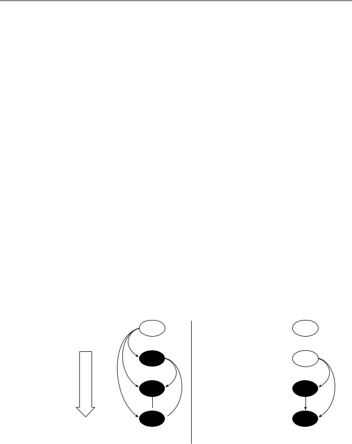
Figure 8-18 shows the procedure of a backup taking over in the case of a failed primary LECS. The LANE network shown in Figure 8-18 has four LECS entities (LECS A, B, C, and D). All the ATM switches in the network are configured with the same LECS address table. After startup, LECS A obtains the LECS address table from the ATM switch it is attached to and finds that it has three LECSs below itself and therefore tries to connect to LECS B, C, and D. LECS B connects to LECS C and LECS D, and LECS C connects to LECS D. There is a downward establishment of VCCs. Because LECS A does not have any VCCs from above, it becomes the primary LECS.
Figure 8-18 LECS redundancy.
Virtual circuits are established from a higher ranking LECS to a lower ranking LECS.
A
Step 1 LECS A loses connectivity to the network.
B |
Step 2a LECS B has no |
|
connections from |
||
|
||
|
any LECS above |
|
|
itself. Becomes new |
|
|
PRIMARY. |
|
C |
|
Step 2b LECS C and D continue to have the connections from
D  B and hence remain BACKUPs.
XA
B
C
D
(a) |
(b) |
8-26 Cisco CCIE Fundamentals: Network Design

LANE Redundancy
During normal network operation, LECS A responds to all the configure requests and the backup LECS (LECS B, C and D) do not respond to any queries. If for some reason the primary LECS (LECS A) fails due to such conditions as a box failure, LECS B loses its VCC from LECS A as do the other LECS.
At this point, LECS B does not have any VCCs from above and therefore is now the highest ranking available LECS in the network. LECS B now becomes the primary LECS. LECS C and LECS D still have connections from higher ranking LECSs and therefore continue to operate in backup mode as shown in Step 2b of Figure 8-18.
LES/BUS Redundancy
The LES/BUS redundancy portion of SSRP supports the configuration of multiple LES/BUS pairs that work in a primary-secondary fashion. However, the mechanisms used here are different from those used for the LECS redundancy described in the preceding section.
Multiple LES/BUS pairs for a given ELAN are first configured into the LECS database. Within this database, each LES/BUS pair is assigned a priority. After initialization, each LES/BUS opens a VCC with the primary LECS using the LECS address discovery mechanism. The LES/BUS pair with the highest priority that has an open VCC to the LECS is assigned as the primary LES/BUS by the primary LECS.
SSRP Usage Guidelines
There are no theoretical limits on the number of LECSs that can be configured using SSRP, however a recommended number is two (one primary plus one backup) or three LECSs (one primary plus two backups). Any more redundancy should be implemented only after very careful consideration because it will add a significant amount of complexity to the network. This added complexity can result in a substantial increase in the amount of time required to manage and troubleshoot such networks.
SSRP Configuration Guidelines
To support the LECS redundancy scheme, you must adhere to the following configuration rules.
Failure to do so will result in improper operation of SSRP and a malfunctioning network.
•Each LECS must maintain the same database of ELANs. Therefore, you must maintain the same ELAN database across all the LECSs.
•You must configure the LECS addresses in the LECS address table in the same order on each ATM switch in the network.
•When using SSRP with the Well Known Address, do not place two LECSs on the same ATM switch. If you place two LECs on the same ATM switch, only one LECS can register the Well Known Address with the ATM switch (through ILMI) and this can cause problems during initialization.
SSRP Interoperability Notes
SSRP can be used with independent third-party LECs if they use ILMI for LECS address discovery and can appropriately handle multiple LECS addresses returned by the ATM switch. For example, the LEC should step through connecting to the list of LECS addresses returned by the ATM switch. The first LECS that responds to the configuration request is the master LECS.
Designing ATM Internetworks 8-27

LANE Implementation
Behavior of SSRP with the Well Known LECS Address
SSRP also works with LECS Well Known Address (47.0079….) defined in the LANE 1.0 specification. The Cisco LECS can listen on multiple ATM addresses at the same time. Therefore, it can listen on the Well Known Address and the auto-configured ATM address, which can be displayed using the show lane default command.
When the LECS is enabled to listen on the Well Known Address, it registers the Well Known Address with the ATM switch so that the ATM switches can advertise routes to the Well Known Address and route any call setups requests to the correct place.
Under SSRP, there are multiple LECSs in the network. If each LECS registers the Well Known Address to the ATM switches that it is connected to, call setups are routed to different places in the network. Consequently, under SSRP you must configure an autoconfigured address so that the negotiation of the master first takes place and then the master registers the Well Known Address with the ATM switch. If the master fails, the Well Known Address moves with the master LECS. The PNNI code on the LightStream 1010 switch takes care of advertising the new route to the Well Known Address when there is a change of LECS mastership. Therefore, third-party LECs that use only the Well Known Address can also interoperate with SSRP. SSRP is the only redundancy scheme that can be used with almost any LEC in the industry.
To implement SSRP with the Well Known Address, use the following steps:
Step 1 Configure the LECS to listen on the autoconfigured address (or if you want a separate ATM address that you have predetermined). This autoconfigured (or other) address should be programmed into the ATM switches for the LECS address discovery mechanism.
Step 2 Configure each LECS to listen on the Well Known address using the lane config fixed-config-atm-address command. After the master LECS is determined using the LECS redundancy procedure, the master registers the Well Known Address to the ATM switch.
Note SSRP with the Well Known Address does not work properly under certain circumstances (during failover) if two LECS are attached to the same ATM switch. This is due to the possibility of duplicate address registration on the same switch, which ILMI does not allow. Make sure each LECS is on a separate ATM switch.
Behavior of SSRP in Network Partitions
In the event of network partitions where two separate ATM clouds are formed due to an interconnecting link or switch failure, each cloud has its own set of LANE services if SSRP is configured to handle network partitions.
When configuring SSRP, use the following guidelines to accommodate the possibility of network partition:
•Configure each partition with its own LANE services that can become active during a network partition. For example, if you are connecting two sites or campuses across a MAN and you want the same ELANs at both locations, configure each campus/site with its own LANE services.
•Routing behavior should be carefully examined during a network partition in the case where an ELAN maps to a Layer 3 network (for example, an IP subnet or IPX network) because there are now two routes to the same subnet (assuming there are redundant routers in the network). If there are no redundant routers, one of the partitions will be effectively isolated from the rest of the network. Intra-ELAN traffic will continue to behave properly.
8-28 Cisco CCIE Fundamentals: Network Design

Role of Stratm Technology
HSRP over LANE
HSRP is a protocol that network designers can use to guard against router failures in the network. The HSRP protocol is exchanged between two routers and one of them is elected as the primary router interface (or subinterface) for a given subnet. The other router acts as the hot standby router.
In HSRP, a default IP address and a default MAC address are shared between the two routers exchanging the HSRP protocol. This default IP address is used as the default gateway at all IP end stations for them to communicate with end stations outside their immediate subnet. Therefore, when there is a primary router failure, the hot standby router takes over the default gateway address and the MAC address so that the end station can continue communicating with end stations that are not in their immediate subnet.
Because HSRP is a Layer 2 mechanism and needs a MAC address-based Layer 2 network, it is possible to implement HSRP style recovery over LANE. The mechanisms used are the same as for any Ethernet interface and can be configured at a subinterface level.
Redundant ATM Port Card for the Catalyst 5000
Another aspect of addressing the redundancy needs from a physical network perspective is the addition of a redundant PHY portion of an ATM card. The Catalyst 5000 switch employs the dual PHY redundant ATM card. This redundancy is only at a physical level and is useful in cases where the primary link to the ATM switch goes down.
Role of Stratm Technology
Stratm Technology is a new approach to ATM switching technology that incorporates patented standards-based Cisco technology into custom silicon. These application-specific integrated circuits (ASICs) dramatically increase ATM efficiency and scalability and significantly lower the absolute cost of delivering ATM solutions. Stratm Technology can be implemented in switches and routers across LANs, campus networks, and WANs, enabling the delivery of high-performance, end-to-end ATM services to meet a wide range of needs.
Benefits of Stratm Technology
The benefits of Stratm Technology include the following:
•
•
•
•
•
Dramatic improvement in network price/performance scalability
Increased application goodput
Protection of technology investments
Increased portability
Guaranteed infrastructure
Each of these benefits is described in more detail in the following sections.
Improved Network Price/Performance Scalability
Stratm Technology features can dramatically improve network price/performance and scalability as follows:
•Support of up to eight OC-3 (155-Mbps) port interfaces per card slot, and up to 12 digital signal Level 3 T3/E3 (45-Mbps) port interfaces per card slot
•A 30 percent increase in SVC completions to more than 4,000 per second per node
Designing ATM Internetworks 8-29

Role of Stratm Technology
•An increase in connection density per switch by 500 percent
•An increase in the buffering capability of each card to 200,000 cells per card, upgradable to nearly one million cells
•A reduction in the price per port for high-speed connections by up to 50 percent
•The ability to support per-virtual-connection control queuing, rate scheduling, statistics collection, and fair sharing of network resources on an individual connection basis
Increased Application Goodput
Intelligent ATM features are embodied in Stratm Technology. These features are designed to increase application goodput dramatically through advanced features, which are distributed throughout the BXM module in silicon.
•Distributed ATM functions—Stratm distributes such ATM services as traffic management, per-VC queuing, class of service (COS) management, SVCs, and multicasting to each card on a silicon chip. Distributed functionality ensures faster, more efficient processing, and it eliminates the possibility of a single point of failure disrupting the entire network.
•Highest bandwidth efficiency —Stratm delivers guaranteed bandwidth on demand, QoS, and fair sharing of network resources to each individual connection. With fast, efficient processing and guaranteed bandwidth, application performance is significantly enhanced.
•Advanced traffic management capabilities —Stratm incorporates the industry’s first
commercially available Virtual Source/Virtual Destination (VS/VD) implementation of the full ATM Forum’s Traffic Management Specification Version 4.0. This ensures the highest efficiency in bandwidth utilization and provides support for the multicasting capabilities required to successfully deliver multimedia and switched internetworking services.
•End-to-end intelligence—With VS/VD implementation, Stratm also represents the industry’s first complete LAN-to-WAN ARB implementation. This feature enables ATM services to be delivered to the desktop, ensuring high performance for the most demanding applications.
Industry-Leading Investment Protection
Stratm allows you to protect your current investments by integrating with today’s network infrastructures, and providing advanced features and functionality to protect investments far into the future. You can protect your technology investment because of the following Stratm capabilities:
•Seamlessly integrates with existing switches—Stratm Technology integrates into Cisco’s ATM switching platforms, allowing you to enhance your investment in Cisco technology.
•Delivers unparalleled performance—Current ATM switching platforms deliver performance that enables end-to-end delivery of high-quality, high-performance network services.
•Delivers the future—Stratm Technology extends the features and functionality of current switches to support next generation requirements. With this technology, you can easily deliver multiple services from a single network infrastructure and ensure the highest QoS possible.
Increases Portability and Guarantees an Infrastructure
With a modular chip set, Stratm increases the portability of standards-based ATM. ATM in silicon stabilizes the transport layer of networks, thereby guaranteeing the necessary infrastructure for efficient, high-performance delivery of emerging multimedia and Internet-based applications.
8-30 Cisco CCIE Fundamentals: Network Design