

Cisco. Fundamentals Network Design - Cisco Press
.pdfToken Ring
The number following dlsw remote-peer is the ring list number. Ring lists are an advanced topic, so for now, specify zero in this space, which indicates that ring lists are not in use. There are other options on the dlsw local-peer and dlsw remote-peer commands, but they are not required. These options are covered in the “DLSw+ Advanced Features” section later in this chapter.
In addition to specifying local and remote peers, you must map the following local data-link controls to DLSw:
•Token Ring¾Define a virtual ring using the source-bridge ring-group command and include a source-bridge command that tells the router to bridge from the external Token Ring to that virtual ring.
•Ethernet¾Map a specific Ethernet bridge group to DLSw.
•SDLC¾Define the SDLC devices and map the SDLC addresses to DLSw+ virtual MAC addresses.
•QLLC¾Define the X.25 devices and map the X.25 addresses to DLSw+ virtual MAC addresses.
•FDDI¾Define a virtual ring using the source-bridge ring-group command and include an SRB statement that tells the router to bridge from the external FDDI to that virtual ring; FDDI is supported in Cisco IOS Release 11.2 on the Cisco 7000 series.
The rest of this section provides sample configurations for Token Ring, Ethernet, SDLC, and QLLC.
Token Ring
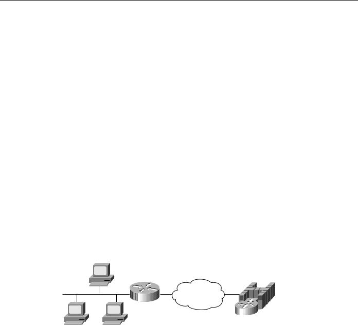
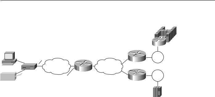
Figure 7-4 shows a sample DLSw+ configuration for Token Ring. Traffic that originates on Token Ring is source-route bridged from the local ring onto a source-bridge ring group and then picked up by DLSw+. You must include a source-bridge ring-group command that specifies a virtual ring number. In addition, you must include a source-bridge command that tells the router to bridge from the physical Token Ring to the virtual ring.
Figure 7-4 Simple Token Ring DLSw+ configuration.
100
Token
Ring 25
Router A
Configuration for Router A source-bridge ring-group 100 dlsw local-peer peer-id 10.2.17.1 dlsw remote-peer 0 tcp 10.2.24.2
.
.
interface TokenRing0 ring-speed 16
source-bridge active 25 1 100 source-bridge spanning
200 |
|
Router B |
Token |
|
|
|
Ring 5 |
Router C |
|
200
Configuration for Router B source-bridge ring-group 200 dlsw remote-peer 0 tcp 10.2.24.2 promiscuous
.
.
interface TokenRing0 ring-speed 16 source-bridge active 5 1 100 source-bridge spanning
Designing DLSw+ Internetworks 7-9
Getting Started with DLSw+
DLSw+ supports RIF termination, which means that all remote devices appear to be attached to the virtual ring specified in the source-bridge command. In Figure 7-4, from the host end, all the devices attached to Router A appear to reside on Virtual Ring 200. Conversely, from the remote site, the FEP appears to reside on Virtual Ring 100. As illustrated in this figure, the virtual rings specified in peer routers do not have to match. If multiple routers are attached to the same physical ring, as shown in Routers B and C, by specifying the same ring group number in each of them, you can prevent explorers from coming in from the WAN and being forwarded back onto the WAN.
Ethernet
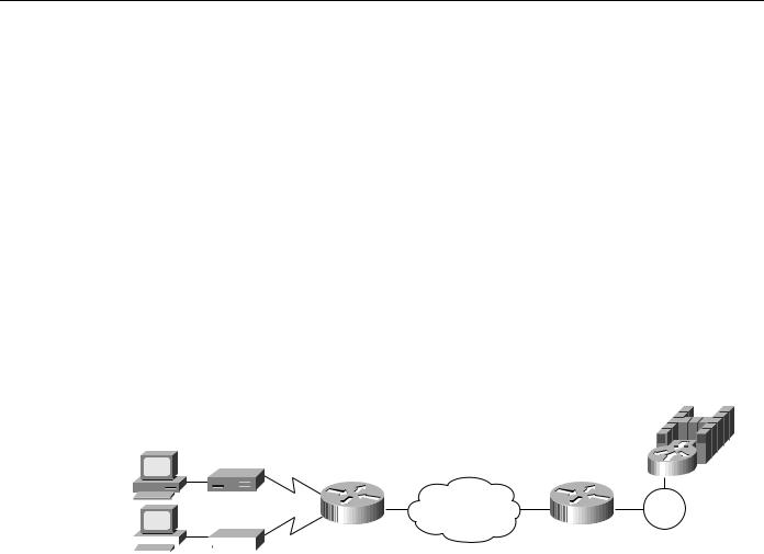
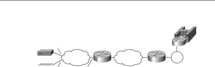
Traffic that originates on Ethernet is picked up from the local Ethernet bridge group and transported across the DLSw network. DLSw always transfers data in noncanonical format. In Figure 7-5, you do not need to configure the left router for translational bridging or worry about what media resides on the other side of the WAN. DLSw will automatically make the correct MAC address conversion depending on the destination media. When DLSw+ receives a MAC address from an Ethernet-attached device, it assumes it is canonical and converts it to noncanonical for transport to the remote peer. At the remote peer, the address is either passed unchanged to Token Ring-attached end systems or converted back to canonical if the destination media is Ethernet. Note that when an SNA resource resides on Ethernet, if you configure a destination SNA address in that device, you must use canonical format. For example, Ethernet-attached 3174s must specify the MAC address of the FEP in canonical format. If the Token Ring or noncanonical format of the MAC address of the FEP is 4000.3745.0001, the canonical format is 0200.ECA2.0080
In Figure 7-5, the data is transferred directly to a Cisco router with a Channel Interface Processor (CIP), but it can be any DLSw-compliant router, and the upstream SNA end system can reside on any supported media.
Figure 7-5 Simple Ethernet DLSw+ configuration.
Router A
dlsw local-peer peer-id 10.2.17.1 dlsw remote-peer 0 tcp 10.2.24.2
.
.
dlsw bridge-group 1 interface Ethernet0 no ip address bridge-group 1 bridge 1 protocol ieee
source-bridge ring-group 200 dlsw remote-peer 0 tcp 10.2.24.2 promiscuous
.
.
interface channel 0/1 csna 0100 40
csna 0100 41 int chan 0/2 lan tokenring0
source-bridge 1000 1 200 adapter 0 4000.0000.0401 adapter 0 4000.0000.0403
7-10 Cisco CCIE Fundamentals: Network Design
SDLC
SDLC
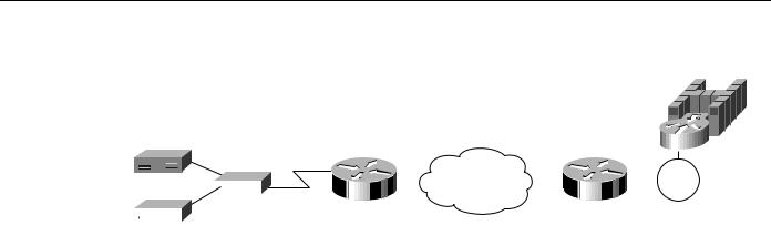
Configuring SDLC devices is a bit more complicated. For SDLC devices, you must know whether the device is a PU 1, PU 2.0, or PU 2.1. For PU 2.0 devices, you must know the IDBLK and IDNUM that was specified in the virtual telecommunications access method (VTAM) for that device because the router plays a greater role in XID processing when SDLC PU 2.0 is involved. You must know if the router is the primary or secondary end of the SDLC line. In addition, if the attachment to the upstream SNA device is over a LAN, you must configure the MAC address of the destination upstream SNA device. In all cases, you must configure a virtual MAC address that will be mapped to an SDLC polling address.
In Figure 7-6, the SDLC-attached devices are each given a common base virtual MAC address of 4000.3174.0000. The router will replace the last two digits of the virtual MAC address with the SDLC address of the device. The device at SDLC address C1 appears to have MAC address 4000.3174.00C1, and the device at SDLC address C2 appears to have MAC address 4000.3174.00C2. In this example, both devices are PU 2.0 devices, so their XID must be configured, and it must match what is specified as the IDBLK and IDNUM in VTAM. In addition, the router always assumes the primary role when attaching upstream from PU 2.0 devices.
Figure 7-6 Simple SDLC DLSw+ configuration.
C1
|
|
|
Token |
C2 |
Router A |
Router B |
Ring |
|
|
|
|
|
|
|
|
|
|
|
|
|
|
|
|
|
|
|
|
|
|
|
|
|
Configuration for Router A |
interface serial1 |
||||||
|
|
|
dlsw local-peer peer-id 10.2.17.1 |
encapsulation sdlc |
||||||
|
|
|
dlsw remote-peer 0 tcp 10.2.24.2 |
sdlc role primary |
||||||
|
|
|
Interface serial 0 |
sdlc vmac 4000.3174.1000 |
||||||
|
|
|
encapsulation sdlc |
sdlc address c2 |
||||||
|
|
|
sdlc role primary |
sdlc xid c1 01767890 |
||||||
|
|
|
sdlc vmac 4000.3174.0000 |
sdlc partner 4000.3745.0001 c2 |
||||||
|
|
|
sdlc address c1 |
sdlc dlsw c2 |
||||||
|
|
|
sdlc xid c1 01712345 |
|
||||||
|
|
|
sdlc partner 4000.3745.0001 c1 |
|
||||||
|
|
|
sdlc dlsw c1 |
|
||||||
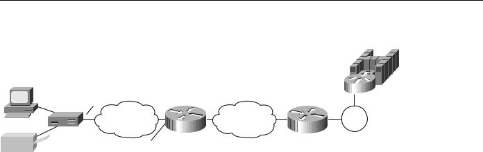
The router can be the secondary end of an SDLC line (for example, when connecting to a FEP over SDLC). In this case, specify secondary in the sdlc role command, and for PU 2.1 devices, specify xid-passthru in the sdlc address command. In Cisco IOS Release 11.0 and later, DLSw+ supports multidrop PU 2.0/2.1. In Figure 7-7, the multidrop PU 2.0 configuration includes an sdlc xid command for each PU 2.0 device.
For multidrop lines with a mix of PU 2.1 and 2.0 devices, specify primary in the sdlc role command. For PU 2.0 devices, you must code the IDBLK and IDNUM in the sdlc xid command. For PU 2.1 devices, you can omit the sdlc xid command. However, in the sdlc address command, you need to specify xid-poll. Alternatively, when all devices on a line are PU 2.1, you can specify sdlc role prim-xid-poll, in which case you do not need to specify xid-poll in each sdlc address command.
Designing DLSw+ Internetworks 7-11
SDLC
Figure 7-7 Multidrop SDLC DLSw+ configuration.
C1
MSD
|
|
|
|
|
|
|
|
|
|
|
|
|
|
|
|
|
|
|
Token |
|
|
C2 |
|
|
|
Router |
A |
|
|
|
|
Router |
B |
|
|
Ring |
|||
|
|
|
|
|
|
|
|
|
|
|
|||||||||
|
|
|
|
|
|
Configuration for Router A |
|
Configuration for Router A, mixed |
|||||||||||
|
|
|
|
|
|
|
|||||||||||||
|
|
|
|
|
|
||||||||||||||
|
|
|
|
|
|
Both C1 and C2 are PU 2.0 |
|
2.0 and 2.1 |
|
||||||||||
|
|
|
|
|
|
dlsw local-peer peer-id 10.2.17.1 |
|
interface serial 0 |
|
||||||||||
|
|
|
|
|
|
dlsw remote-peer 0 tcp 10.2.24.2 |
|
… |
|
||||||||||
|
|
|
|
|
|
Interface serial 0 |
|
sdlc role primary |
|
||||||||||
|
|
|
|
|
|
mtu 4400 |
|
|
|
|
|
sdlc vmac 4000.3174.0000 |
|
||||||
|
|
|
|
|
|
no ip address |
|
|
|
|
|
sdlc address c1 xid poll |
|
||||||
|
|
|
|
|
|
encapsulation sdlc |
|
sdlc partner 4000.3745.0001 c1 |
|||||||||||
|
|
|
|
|
|
no keepalive |
|
|
|
|
|
sdlc address c2 |
|
||||||
|
|
|
|
|
|
clockrate 19200 |
|
sdlc xid c1 01767890 |
|
||||||||||
|
|
|
|
|
|
sdlc role primary |
|
sdlc partner 4000.3745.0001 c2 |
|||||||||||
|
|
|
|
|
|
sdlc vmac 4000.3174.0000 |
|
sdlc dlsw c1 c2 |
|
||||||||||
|
|
|
|
|
|
sdlc address |
c1 |
|
Configuration for Router A all PL |
||||||||||
|
|
|
|
|
|
sdlc xid c1 01712345 |
|
|
|
|
|
|
|
|
|||||
|
|
|
|
|
|
sdlc partner 4000.3745.0001 c1 |
|
interface serial 0 |
|
||||||||||
|
|
|
|
|
|
sdlc address |
c2 |
|
… |
|
|||||||||
|
|
|
|
|
|
sdlc xid c1 01767890 |
|
sdlc role prim-xid-poll |
|
||||||||||
|
|
|
|
|
|
sdlc partner 4000.3745.0001 c2 |
|
sdlc Vamc4000.3174.000 |
|
||||||||||
|
|
|
|
|
|
sdlc dlsw c1 c2 |
|
sdlc address c1 |
|
||||||||||
|
|
|
|
|
|
|
|
|
|
|
|
|
sdlc partner4000.3745.000c1 |
||||||
|
|
|
|
|
|
|
|
|
|
|
|
|
sdlc address c2 |
|
|||||
|
|
|
|
|
|
|
|
|
|
|
|
|
sdlc partner4000.3745.000 |
|
|||||
QLLC
QLLC is the data link used by SNA devices when connecting to X.25 networks. QLLC is a legacy protocol developed by IBM to allow the Network Control Program (NCP) to support remote connections over X.25. The software feature on NCP that supports QLLC is called Network Packet Switching Interface. The QLLC protocol derives its name from using the Q-bit in the X.25 header to identify QLLC protocol primitives. QLLC essentially emulates SDLC over X.25. Thus, DLSw+ performs QLLC conversion in a manner similar to SDLC conversion. Cisco’s DLSw+ implementation added support for QLLC in Cisco IOS Release 11.0. Because QLLC is more complicated than Token Ring, Ethernet, or SDLC, three examples are included here.
Figure 7-8 shows DLSw+ being used to allow remote devices to connect to a DLSw+ network over an X.25 public packet switched network. In this example, all QLLC traffic is addressed to destination address 4000.1161.1234, which is the MAC address of the FEP. The remote X.25-attached 3174 is given a virtual MAC address of 1000.0000.0001. This virtual MAC address is mapped to the X.121 address of the 3174 (31104150101) in the X.25 attached router.
7-12 Cisco CCIE Fundamentals: Network Design
QLLC
Figure 7-8 QLLC DSLw+ configuration to a single LAN-attached upstream device.
|
Virtual MAC address |
|
representing the 3174 |
31104150101 |
1000.0000.0001 |
X.25 |
DLSw+ |
|
Router A |
3110212011
Configuration for Router A
dlsw local-peer peer-id 10.2.17.1 dlsw remote-peer 0 tcp 10.2.24.2 Interface serial 0
encapsulation x25
x25 address 3110212011
x25 map qllc 1000.0000.0001 31104150101 qllc dlsw partner 4000.1161.1234
4000.1161.1234
Token
Ring
In Figure 7-9, a single 3174 needs to communicate with both an AS/400 and a FEP. The FEP is associated with subaddress 150101, and the AS/400 is associated with subaddress 150102. If an X.25 call comes in for 33204150101, the call is mapped to the FEP and forwarded to MAC address 4000.1161.1234. The 3174 appears to the FEP as a Token Ring-attached resource with MAC address 1000.0000.0001. The 3174 uses a source SAP of 04 when communicating with the FEP.
If an X.25 call comes in for 33204150102, the call is mapped to the AS/400 and forwarded to MAC address 4000.2034.5678. The 3174 appears to the AS/400 as a Token Ring-attached resource with MAC address 1000.0000.0001. The 3174 uses a source SAP of 08 when communicating with the AS/400.
Designing DLSw+ Internetworks 7-13
SDLC
Figure 7-9 QLLC DLSw+ configuration for support of multiple upstream LAN-attached devices.
|
Virtual MAC address |
|
representing the 3174 |
33204 |
1000.0000.0001 |
X.25 |
DLSw+ |
|
Router A |
31102
Configuration for Router A
dlsw local-peer peer-id 10.2.17.1 dlsw remote-peer 0 tcp 10.2.24.2 Interface serial 0
encapsulation x25 x25 address 31102
x25 map qllc 1000.0000.0001 33204
qllc dlsw subaddress 150101 partner 4000.1161.1234 sap 04 04
qllc dlsw subaddress 150102 partner 4000.2034.5678 sap 08 04
4000.1161.1234
Token
Ring
Token
Ring
4000.2034.5678
AS/400
In Figure 7-10, two X.25 resources want to communicate over X.25 to the same FEP. In the router attached to the X.25 network, every X.25 connection request for X.121 address 31102150101 is directed to DLSw+. The qllc dlsw command creates a pool of two virtual MAC addresses, starting with 1000.0000.0001. The first switched virtual circuit (SVC) established will be mapped to virtual MAC address 1000.0000.0001. The second SVC will be mapped to virtual MAC address 1000.0000.0002.
7-14 Cisco CCIE Fundamentals: Network Design
DLSw+ Advanced Features
Figure 7-10 QLLC DLSw+ configuration for support of multiple downstream X.25-attached devices communicating through an upstream DLSw+ network.
C1 33204
C2
 35765
35765
X.25 |
DLSw+ |
|
Router A |
31102
Configuration for Router A
dlsw local-peer peer-id 10.2.17.1 dlsw remote-peer 0 tcp 10.2.24.2 Interface serial 0
encapsulation x25 x25 address 31102 x25 map qllc 33204 x25 map qllc 35765
qllc dlsw subaddress 150101 vmacaddr 1000.0000.0001 2 partner 4000.1161.1234
4000.1161.1234
Token
Ring
DLSw+ Advanced Features
This section describes advanced features of DLSw+, the benefits they provide, and a brief description of when and how to use them. Use this section to determine which options you want to use and to learn how to configure those options to address your requirements.
DLSw+ includes features to enhance availability (load balancing, redundancy, and backup peers), improve performance (encapsulation options), minimize broadcasts (ring lists), and build meshed networks (border peers and peer groups). DLSw+ also provides a feature to maximize central site resources and minimize carrier costs (dynamic peers). Advanced features are optional and do not apply in all networks. Each feature includes a description of where it should be used.
How DLSw+ Peers Establish Connections
To understand load balancing, it is useful to understand how DLSw+ peers establish peer connections and find resources. When DLSw+ routers are activated, the first thing they do is establish peer connections with each configured remote peer (unless passive is specified, in which case a peer will wait for the remote peer to initiate a peer connection). The routers then exchange their capabilities. Included in the capabilities exchange are any resources configured in dlsw icanreach or dlsw icannotreach commands. After the capabilities exchange, the DLSw+ peers are idle until an end system sends an explorer frame (explorer frames are SNA TEST or XID frames or NetBIOS NAME-QUERY or ADD NAME-QUERY frames). Explorer frames are forwarded to every active peer and any local ports (other than the port it was received on). It is possible that an end system can be found through multiple remote peers or local ports. The path selected for a given circuit depends on certain advanced configuration options described in this section.
Designing DLSw+ Internetworks 7-15

DLSw+ Advanced Features
Load Balancing and Redundancy
If you have multiple central site routers supporting DLSw+ for either load balancing or redundancy, this section contains important information. It describes how to balance traffic across multiple central site routers or multiple ports on a single router. Load balancing in this case does not refer to balancing traffic across multiple WAN links or IP paths. That load balancing is done by the underlying IP protocol and is transparent to DLSw+.
If DLSw+ gets multiple positive replies to an explorer, it will cache up to four peers that can be used to reach a remote end system and up to four ports that can be used to reach a local end system. How these cache entries are used depends on whether load balancing is specified on the dlsw duplicate- path-bias command. If load balancing is specified, each new circuit request is established over the next path (remote peer or local port) in the cache in a round-robin fashion.
If load balancing is not specified, the peer selects the first path in the cache and sets up all circuits via that path unless the path is unavailable. The first path in the cache list can be one of the following:
•
•
•
Peer from which the first positive response was received
Peer with the least cost
Port over which the first positive response was received
Cost can be specified on either a dlsw local-peer or a dlsw remote-peer command. When specified on a dlsw local-peer command, it is exchanged with remote DLSw+ peers as part of the capabilities exchange. The following example shows how cost can be used to control the path that sessions use.
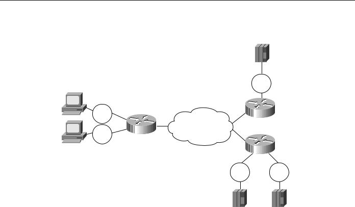
In Figure 7-11, there are two channel gateways and three Token Ring adapters that can be used to access mainframe applications. All three adapters have been assigned the same MAC address. Assigning duplicate addresses is a common technique for providing load balancing and redundancy in SRB environments. It works because SRB assumes that there are three paths to find the same device and not duplicate LAN addresses. (This technique does not work with transparent bridging.)
7-16 Cisco CCIE Fundamentals: Network Design
Load Balancing and Redundancy
Figure 7-11 Possible configuration and the resulting cache entries created when all channel gateways have the same MAC address.
MAC 1 Peer C (p)
Token Peer B (c)
Ring
Token |
Peer A |
Ring |
|
Peer A configuration
dlsw local-peer peer-id 10.2.17.1 dlsw remote-peer 0 tcp 10.2.24.2 dlsw remote-peer 0 tcp 10.2.24.3
|
Token |
|
Ring |
|
Peer B |
|
MAC 1Port 1 (p) |
|
Port 2 (c) |
|
Peer C |
Token |
Token |
Ring |
Ring |
Peer B configuration
dlsw local-peer peer-id 10.2.24.3 promiscuous
Peer C configuration
dlsw local-peer peer-id 10.2.24.2 promiscuous
dlsw duplicate-path-bias load-balance
In this example, Peer A has dlsw remote-peer commands for both Peer B and Peer C. Peer B specifies a cost of four in its dlsw local-peer command and Peer C specifies a cost of two. This cost information is exchanged with Peer A during the capabilities exchange.
When the SNA end system (that is, the PU) on the left sends an explorer packet, Peer A forwards the explorer to both Peer B and Peer C. Peer B and Peer C forward the explorer on their local LAN. Peer B will receive a positive reply to the explorer and send a positive response back to Peer A. Peer C will receive two positive replies (one from each port) and will send a positive reply back to Peer A. Peer C records that it has two ports it can use to reach the MAC address of the channel gateway, and Peer A records that it has two peers it can use to reach the MAC address of the channel gateway.
Peer A will forward a positive response to the SNA PU and then establish an end-to-end circuit using Peer C. Peer C is selected because it has a lower cost specified. When the next PU attempts to set up a connection to the same MAC address, it will be set up using Peer C, if available. This is the default method to handle duplicate paths in DLSw+.
At Peer C, the first circuit will be established using Port 1, but the next circuit will use Port 2. This is because Peer C has specified load balancing in the dlsw duplicate-path-bias command. Each new SNA PU will use the next path in the list in a round-robin fashion.
Figure 7-11 shows how to cause all remote connections to prefer one peer over another, but the central site load balances traffic across all the LAN adapters on a given channel gateway. Alternatively, load balancing can be specified everywhere to load balance traffic across all central site routers, channel gateways, and LANs. Note that this feature does not require the end systems to be Token Ring-attached. The remote end systems can connect over SDLC, Ethernet, or QLLC, and
Designing DLSw+ Internetworks 7-17
DLSw+ Advanced Features
this feature will still work. The central site channel gateway must be LAN-attached (preferably Token Ring-attached). Duplicate MAC addresses for channel gateways on Ethernet will only work when 1) you have a unique bridged Ethernet segment and a unique DLSw+ router for each duplicate MAC address, and 2) you load balance from the remote sites. (Ethernet has no provision to prevent loops, so care must be taken when building redundant networks with Ethernet LANs. Token Ring networks can rely on SRB for loop prevention.)
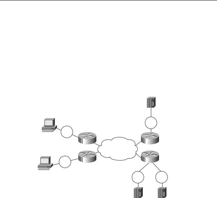
An alternative way to specify cost is to use the dlsw remote-peer command as shown in Figure 7-12. Specifying cost in the dlsw remote-peer commands allows different divisions or parts of the country to favor different central site gateways. In addition, you must specify cost if you want to split SNA traffic across multiple central site routers, but each remote site has only a single SNA PU (all logical unit sessions flow over the same circuit that the PU session flows over). In Figure 7-12, Peer A always favors Peer B and Peer D always favors Peer C.
Figure 7-12 Configuration where cost is specified in the disw remote-peer command instead of the disw local-peer command.
Token
Ring
|
Peer A |
Token |
Peer D |
Ring |
|
Peer A configuration
dlsw local-peer peer-id 10.2.17.1
dlsw remote-peer 0 tcp 10.2.24.2 cost 2 dlsw remote-peer 0 tcp 10.2.24.3 cost 4
Peer D configuration
dlsw local-peer peer-id 10.2.18.6
dlsw remote-peer 0 tcp 10.2.24.2 cost 4 dlsw remote-peer 0 tcp 10.2.24.3 cost 2
|
Token |
|
Ring |
|
Peer B |
|
Peer C |
Token |
Token |
Ring |
Ring |
Peer B configuration
dlsw local-peer peer-id 10.2.24.2 promiscuous
Peer C configuration
dlsw local-peer peer-id 10.2.24.3 promiscuous
dlsw duplicate-path-bias load-balance
Controlling Peer Selection
A higher-cost peer can be used for a connection even when the lower-cost peer is active if the higher-cost peer responds to the explorer before the lower-cost peer. If your network configuration allows this possibility, you can prevent it by adjusting a timer.
7-18 Cisco CCIE Fundamentals: Network Design