

Cisco. Fundamentals Network Design - Cisco Press
.pdfSTUN Configuration for SDLC
larger than the next expected sequence number. The algorithm is not important, but the rule is that the receiving FEP propagates PIUs by sequence number order. PIUs with a lower sequence number than expected are considered duplicates and are discarded.
Later versions of NCP deviate from the SDLC standard in their use of SDLC echo addressing. The SDLC secondary NCP sets the high-order bit of the SDLC address when sending a response. For example, the primary NCP sends frames with address 01, and the secondary NCP sends frames with address 81. This addressing scheme limits the range of SDLC addresses from 01 to 7F. Additionally, SDLC address FF is used on frames preceding and during the NCP’s XID exchange. The XID and DM frames use the broadcast address.
Another deviation from the SDLC standard occurs in NCP-to-NCP communication when a host NCP loads a remote NCP. Normally, numbered information frames can be sent only after an SNRM (or SNRME), which resets the station counts to ensure that the two stations start with consistent counts. When a host NCP loads a remote NCP, the host sends a Set Initialization Mode (SIM), and the remote NCP responds with a Request Initialization Mode (RIM), which allows numbered information frames to flow. NCPs are allowed to violate the SDLC standard because these violations (echo addressing, broadcast addressing, and sending numbered information frames before SNMRE) occur only when an NCP communicates with another NCP.
NCP-to-NCP Communications over a Routed Network
There are several reasons for routers to carry NCP-to-NCP traffic. Routers allow other protocols to share high-cost bandwidth (such as leased lines) that is set aside for SNA traffic. In the traditional NCP-to-NCP communications, a leased line is required for each line in a transmission group.
However, routers enable a number of leased lines to be collapsed into one leased line. In addition, routing capabilities enable routers to dynamically determine wide-area network paths, which can result in a more reliable network.
Figure 5-9 illustrates NCP-to-NCP communications in a router-based internetwork.
Figure 5-9 NCP-to-NCP communications over a routed network.
IBM host Primary FEP |
|
Secondary FEP |
0 |
S1 |
S0 Router B S1S0 |
S0 Router A S1 |
||
|
TO0 |
S1 |
|
TO0 |
|
|
Token |
Token |
|
Ring |
Ring |
Changing from STUN pass-through to STUN local acknowledgment has the following benefits:
•
•
•
•
Keeps SDLC poll (RR) traffic off of an overutilized WAN
Prevents NCP timers from expiring due to network delay
Collapses multiple WAN leased lines into one leased line
Reduces store-and-forward delays through the router network
Consider the situation illustrated in Figure 5-9. Notice that the router attached to the SDLC primary NCP (Router A) acts as an SDLC secondary station, and vice versa for the other router (Router B). For this discussion, assume that all serial links between NCPs and routers are in the same transmission group. This means that the NCP considers the lines to be in transmission group X, and the router considers the lines to be in transmission group Y. There is no relationship between X and Y. X is used in the NCP system generation, and Y is used in the router configuration.
Designing SDLC, SDLLC, and QLLC Internetworks 5-11

SDLC via STUN
Transmission Group and CoS Support
The following features facilitate the support of transmission groups and CoS in Cisco routers:
•SDLC address violation allowances
Two specific instances are exempt from SDLC addressing restrictions:
—Echo addressing
—Broadcast addressing
•Remote NCP load sequence
During the load sequence, the remote NCP performs minimal SDLC functions. It cannot go into Normal Response Mode (NRM) until it is loaded. The load sequence for a remote NCP starts with a SIM/RIM exchange between NCPs, which initializes each NCP’s SDLC frame count to zero. After the SIM/RIM exchange, the NCPs pass numbered information frames; this event normally does not occur until after a SNRM/UA sequence. The router’s SDLC transmission group local-acknowledgment support allows loading of remote NCPs when the routers pass through all frames after a SIM/RIM sequence and before a SNRM/UA sequence. After the SNRM/UA exchange, normal local acknowledgment occurs.
•Rerouting in multilink transmission groups
When a router acknowledges an Information frame, it must ensure delivery of that frame to the receiving NCP. If, after the frame is locally acknowledged, the corresponding link in the receiving transmission group is lost, the receiving router reroutes the frame onto another SDLC link in the same transmission group.
•CoS
The sending NCP performs CoS. Each PIU is assigned a sequence number. The best service the routers can perform is to try to preserve the CoS as assigned by the sending NCP via sequence numbers. Therefore, all SNA data PIUs are treated equally with the goal to preserve PIU order. However, virtual route-pacing responses flow at SNA network priority level and do not have sequence numbers (that is, they have a sequence number of 0). The router prioritizes all SNA network priority PIUs higher than SNA data to achieve more efficient virtual route pacing.
Note The router cannot use the PIU to determine whether traffic is interactive or batch. Even if the router could make this determination, prioritizing one type of traffic over another would cause the receiving NCP to waste CPU time resequencing the PIUs. This would also degrade throughput because the receiving NCP would hold PIUs longer when resequencing.
•Flow control tuning for better CoS operation
The tcp-queue-max keyword of the stun route address tcp global configuration command allows you to tune the size of the outbound TCP queue so that when the WAN becomes congested, frames generated by an NCP can be stored in the router as well as in the NCP. When the size of the outbound TCP queue is small, back-pressure via SDLC RNRs is applied to sending NCPs sooner, causing the NCP to hold more frames. The more frames that are held by the NCP, the more frames to which the NCP’s CoS algorithm is applied. The size of the outbound TCP queue should be configured to 70 or above.
5-12 Cisco CCIE Fundamentals: Network Design

STUN Configuration for SDLC
Transmission Group and CoS Design Guidelines and Notes
The following guidelines should be considered when implementing transmission groups and CS:
1Bandwidth of the WAN should be greater than, or equal to, the aggregate bandwidth of all the serial lines. If other protocols are also using the WAN, bandwidth of the WAN should be greater than the aggregate bandwidth of all the serial lines.
2If the network delay associated with one line of an NCP transmission group is different from the network delay associated with another line in the same NCP transmission group, the receiving NCP spends additional time resequencing PIUs. This happens when one or more of the NCP transmission group lines is routed and one or more lines is directly connected between NCPs.
3The Software Release 9.1 prioritizing algorithm ensures that only the highest priority traffic is guaranteed to get through. Software Release 9.21 prioritization is enhanced by the addition of custom queuing. Custom queuing can be used to guarantee specific bandwidth allocated to protocols with respect to bandwidth allocated to other protocols.
If you are using Software Release 9.1 and an SNA WAN as a multiprotocol backbone, give SNA traffic the highest priority and assign the next highest priority to other missioncritical protocols. In addition, make sure that your WAN bandwidth is significantly greater than your aggregate SNA serial line bandwidth so that your SNA traffic does not monopolize the WAN.
Table 5-4 lists equivalent commands for configuring priority queuing and custom queuing.
Table 5-4 |
Comparison of Priority Queuing and Custom Queuing Configuration |
|
|
Commands |
|
|
|
|
Priority Queuing |
Custom Queuing |
|
|
|
|
priority-list 4 protocol ip high tcp 1994 |
queue-list 2 protocol ip 1 tcp 1994 |
|
|
|
|
priority-list 4 protocol ip medium tcp 1992 |
queue-list 2 protocol ip 2 tcp 1992 |
|
|
|
|
priority-list 4 protocol ip normal tcp 1991 |
queue-list 2 protocol ip 3 tcp 1991 |
|
|
|
|
priority-list 4 protocol ip low tcp 1990 |
queue-list 2 protocol ip 4 tcp 1990 |
|
|
|
|
4When NCPs are directly connected, their poll-and-pause timers should be configured for maximum throughput using the NCP PAUSE statement. Configuration of this parameter depends on whether the NCP is acting as a primary or secondary SDLC station. Table 5-5 outlines the defaults and recommendations as specified in the IBM publication Tuning and Problem Analysis for NCP SDLC Devices.
Table 5-5 |
NCP PAUSE Parameter Guidelines |
|
|
|
|
Pause Statement Parameter |
IBM Guideline |
|
|
|
|
NCP primary PAUSE |
Specifies the time the NCP will wait between sending polls if it has no data to |
|
|
|
send. (Default is 0.2 seconds; 0 is recommended.) |
|
|
|
NCP secondary PAUSE |
Specifies the time that the secondary NCP will wait before returning a frame with |
|
|
|
the final bit set. (Default is 0.2 seconds; recommended to be high –0.2 to 1.0 |
|
|
seconds.) |
|
|
|
Adding routers with local acknowledgment creates two SDLC sessions instead of one. The result is that the two SDLC sessions do not preserve the original characteristics of the original NCP-to-NCP SDLC session. To adapt a secondary NCP to the router environment, change its system generation PAUSE statement to a value between 0.0 and 0.1 seconds, inclusive.
Designing SDLC, SDLLC, and QLLC Internetworks 5-13

SDLC via STUN
SNA Host Configuration Considerations for STUN
When designing STUN-based internetworks featuring routers and IBM SNA entities, you must carefully consider the configuration of SNA nodes and routing nodes. Appendix D, “SNA Host Configuration for SDLC Networks,” provides examples of SNA host configurations that focus on two specific SNA devices:
•
•
FEP configuration for SDLC links
3174 SDLC configuration example
STUN Implementation Checklist
Before implementing a serial tunneling (STUN) internetwork, make sure you are familiar with Synchronous Data Link control (SDLC). Depending on your implementation, you may need to review the “SDLC via STUN” section at the beginning of this chapter.
Use the following steps as a checklist when implementing SDLC STUN in your internetwork:
Step 1 Evaluate your current environment by answering the following questions:
•What host-attached cluster controllers or front end processors (FEPs) are being used (such as 37x5, 3172, and 3174)? The host site might be referred to as a local, core, or backbone site, or as a data center.
•Through what media is the network connected to the host site?
—STUN: Serial connection at both ends.
—SDLLC: Token Ring at primary station and SDLC at secondary station, or Ethernet at primary stations and SDLC at secondary station.
—Reverse SDLLC: SDLC at primary station and Token Ring or Ethernet at secondary station.
•What are the link speeds for local and remote end systems?
•What are the current SDLC line utilization measurements of those links that will attach to the router? This information will be helpful in determining the site requirements.
•What interface types are to be used (for example, V.24 [EIA/TIA-232, formerly RS-232], V.35, X.21)?
•What modems, data service units (DSUs), channel service units (CSUs), or modem-sharing or line-sharing devices are to be used?
•What remote end system types are involved (for example: 3174, 3274, or AS/400)?
•What kind of emulation requirements are involved (for example: half or full duplex, NRZ or NRZI)?
•What are the current transaction response times? Consider peak load periods and characterize traffic patterns.
•How many PUs are in place? How many are planned? This information is important for router utilization sizing.
•How many LUs are in place? How many are planned? Many busy LUs attached to a PU will increase link utilization.
Step 2 Determine current host configurations. Important information includes the following:
•If the FEP is a 3745, 3725, or 3720, the Network Control Program (NCP) definition listing, especially the GROUP, LINE, PU, and LU definition statements.
5-14 Cisco CCIE Fundamentals: Network Design

SDLLC Implementation
•
•
•
Remote controller configuration worksheets for 3x74, 5x94.
OS/2 Communication Manager configuration files.
Network topology diagram.
Step 3 Determine what router-based IBM features will best suit your requirements:
•If remote devices are SDLC-attached PU type 2 devices, consider using SDLLC. See the following section, “SDLLC Implementation.”
•Depending on the specific situation, STUN can be used in many instances and supports all PU types.
Step 4 Determine what FEP-to-NCP conversion changes are required:
•Are FEP lines multidrop? Is virtual multidrop required? Refer to the “Virtual Multidrop” section earlier in this chapter.
•Do PU addresses require changing if SDLC address prioritization is used? Refer to the “SDLC Address Prioritization” section earlier in this chapter.
•Does the reply timeout T1 timer need to be increased to accommodate network delays if local acknowledgment is not used?
•Does the “Retries” parameter need to be adjusted for longer elapsed retry sequences?
Step 5 Determine how end-station controllers are configured and, if possible, configure the router to accommodate them:
•Addresses might need to be changed if you use virtual multidrop. Refer to the “Virtual Multidrop” section earlier in this chapter.
•NRZ support might be required depending on router platform and interface used. Refer to the “Supported Data-Link Configurations” section earlier in this chapter.
•If the controller toggles RTS (assumes half-duplex mode), refer to the “Supported Data-Link Configurations” section earlier in this chapter.
SDLLC Implementation
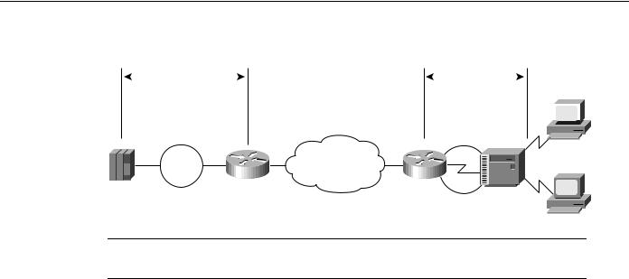
The SDLLC function allows serial-attached devices using the SDLC protocol to communicate with LAN-attached devices using the LLC2 protocol. The basic purpose of the SDLLC function is to consolidate the traditionally disparate SNA/SDLC networks onto a LAN-based, multiprotocol, multimedia backbone network.
Routers use the SDLLC feature to terminate SDLC sessions, to translate SDLC to the LLC2 protocol, and to forward the LLC2 traffic through remote source-route bridging (RSRB) over a point-to-point or IP network. Because a router-based IP network can use any arbitrary media, such as FDDI, Frame Relay, X.25, or leased lines, routers support SDLLC over all such media through IP encapsulation. Figure 5-10 illustrates a general SDLLC media translation internetwork arrangement.
Designing SDLC, SDLLC, and QLLC Internetworks 5-15
SDLLC Implementation
Figure 5-10 |
SDLLC media translation. |
|
|
|
|
|
|||
|
|
LLC2 |
|
SDLC |
|
|
|
||
|
|
session |
|
|
|
session |
|
|
IBM |
|
|
|
|
|
|||||
|
|
|
|
|
|
|
3278 |
||
|
|
|
|
|
|
|
|
|
|
|
|
|
|
|
|
|
|
|
|
|
|
|
IBM |
|
|
|
|
|
3x74 |
|
|
Token |
|
Arbitrary |
|
IBM |
|
|
WAN |
|
3278 |
||
Ring 10 |
Router |
Router |
|||
backbone |
|
||||
|
|
|
|
||
|
|
|
Virtual Token Ring |
|
|
|
|
|
(MAC address) |
|
Note In Figure 5-10, the Token Ring connection (Token Ring 10) could also be an Ethernet segment that connects the FEP or 3172 and router.
SDLLC Configuration
The following sections provide design and implementation information for the following
SDLLC-related configuration topics:
•
•
•
•
Local Acknowledgment
Multidrop Access
Router Configuration
Encapsulation Overhead
Local Acknowledgment
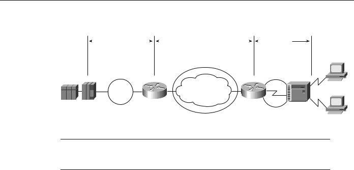
Local acknowledgment of LLC2 sessions allows frames to be locally terminated by the Token Ring-attached router, which guarantees delivery to the ultimate destination through the reliable transport services of TCP/IP. Locally terminating LLC2 sessions enables packet reception to be locally acknowledged, prevents acknowledgment and keepalive traffic from traversing the backbone, and preserves SNA sessions if the network fails. The router that is performing the media translation always acknowledges the SDLC session in an SDLLC environment.
Local acknowledgment locally terminates supervisory frames, which include receiver-ready, receiver-not-ready, and reject frames. Figure 5-11 illustrates the operation of local acknowledgment.
5-16 Cisco CCIE Fundamentals: Network Design
SDLLC Configuration
Figure 5-11 |
Local acknowledgment operation. |
|
|
||||||||
|
|
|
LLC2 |
|
|
|
TCP/IP |
|
|
|
SDLC |
|
|
session |
|
session |
|
session |
|||||
IBM 3278
|
|
|
IBM |
|
|
|
|
3x74 |
|
Token |
|
Arbitrary |
IBM |
|
|
WAN |
3278 |
||
Ring 10 |
Router |
|||
backbone |
Router |
|||
|
|
|
||
3745 |
|
|
|
|
|
|
Virtual ring 100 |
Virtual ring 200 |
Note Local acknowledgment requires that TCP sessions be maintained between the routers. It is not uncommon to see high router CPU utilization at idle traffic times and then decreased utilization as traffic increases. Polling overhead in the router may increase processor use.
Multidrop Access
There are two ways to configure multidrop operation for the SDLC link in an SDLLC environment. The first way is to use a line-sharing device or a modem-sharing device (MSD) to connect multiple controllers at a single site to a single SDLC port on the router. The second way is to connect multiple controllers at different sites through a multidrop service provided by a telephone company. For more information about multidrop connections, refer to Appendix B, “IBM Serial Link Implementation Notes.”
Consider line speed, link utilization, and the number of controllers that will share a single line when designing a multidrop environment. In addition, consider the number of attached LUs associated with individual PUs, and determine if these LUs are being heavily used. If so, increase the bandwidth of the attached serial line. When implementing multidrop environments featuring large numbers of PUs and LUs, contact your technical support representative for specific capabilities.
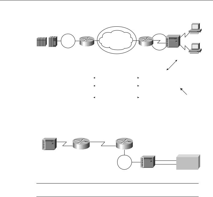
Router Configuration
To configure a router for SDLLC, you need certain virtual telecommunications access method (VTAM) and NCP definition statements. Figure 5-12 illustrates the required configuration information.
Designing SDLC, SDLLC, and QLLC Internetworks 5-17
SDLLC Implementation
Figure 5-12 Required end-to-end SDLLC information.
|
|
|
Virtual ring 100 |
3745 |
|
A |
|
VTAM FEP |
|
Arbitrary |
|
|
Token |
|
|
|
|
WAN |
|
|
Ring 2 |
|
|
|
Router |
backbone |
|
|
|
Virtual ring 200 4000 0000 0100
B
Router
IBM 3x74 Addr=C1
SWMAJ node: |
|
sdlc address C1: |
IDBLK=0E2, IDNUM=00001 |
|
sdllc xid C1 0E200001 |
|
||
PATH=10144000000001C1 |
|
sdllc traddr 4000 000 0100 200 1 100 |
|
||
TIC address: |
|
|
4000 0000 0001 |
|
sdllc partner 4000 0000 0001 C1 |
|
Consider an example of two routers that implement the SDLLC functionality in an environment that interconnects a remote site to a host channel attached to a 3174 Token Ring gateway, as shown in Figure 5-13.
Figure 5-13 SDLLC implementation with 3174 Token Ring gateway.
SDLC |
Leased |
|
link |
line |
|
Router 1 |
Router 2 |
|
3174R |
|
|
Cluster controller |
Token |
Channel |
|
IBM host |
|
|
Ring |
|
|
|
3174L |
|
|
Token Ring gateway |
Note Routers also support SDLLC implementations in environments with a 3745 Token Ring gateway.
The following conditions apply to the sample network illustrated in Figure 5-13:
•The SDLC address of the 3174R is C1.
•The device called 3174L is a 3174 Token Ring that is channel attached to an IBM mainframe.
The 3174R must be defined in the configuration of the 3174L using the virtual Token Ring MAC address. This address is created in the router configuration; it includes the SDLC address as the last byte. This virtual MAC address is mapped to a host subchannel address. One host subchannel address is assigned for each downstream physical unit at host system generation time. PU and LU functions are defined to VTAM within the switched major node function. The following configuration commands are required on Router 1:
•The sdllc traddr interface configuration command with a virtual ring address for the 3174R. Note that the last byte must be 00 and that you must specify the appropriate SDLC address (in this case, C1) for the same last byte during the 3174L customization.
5-18 Cisco CCIE Fundamentals: Network Design

SDLLC Guidelines and Recommendations
•The sdllc partner interface configuration command with the MAC address of the 3174L gateway and the SDLC address of the 3174R.
•The following version of the sdllc xid interface configuration command:
sdllc xid c1 00000000
The sdllc xid interface configuration command is specified with all zeros in the IDBLK/IDNUM field to establish the LLC session between Router 1 and the 3174L. All zeros in the node ID field of the XID command indicate that there is no unique node identifier in this field.
Encapsulation Overhead
Cisco routers provide several types of encapsulation solutions. Because encapsulation always incurs a certain amount of overhead, you need to assess the advantages and performance trade-offs of each encapsulation solution within the constraints of your environment.
TCP/IP encapsulation is recommended most frequently because it is very robust, provides a high quality of service, and is media independent. If SDLLC local acknowledgment is required, TCP/IP encapsulation is required. If SDLLC local acknowledgment is not required, Fast-Sequenced Transport (FST) encapsulation is highly recommended because it is less CPU intensive.
Direct High-Level Data Link Control (HDLC) encapsulation can be used only in point-to-point environments. FST and direct HDLC encapsulation are comparable in performance, but FST has more overhead, which may be an issue on low-speed serial links. TCP/IP encapsulation has the most overhead in terms of processor utilization and the WAN connection. If TCP/IP encapsulation with header compression is a requirement, use it only on link speeds of 64 Kbps or less.
Table 5-6 outlines encapsulation overhead for SDLLC and RSRB implementations.
Table 5-6 |
SDLLC and RSRB Encapsulation Overhead |
|
||
|
|
|
|
|
|
|
|
TCP/IP with Header |
|
TCP/IP |
|
FST |
Compression |
HDLC |
|
|
|
|
|
CPU intensive |
|
Less CPU intensive |
Very CPU intensive |
Least CPU intensive |
|
|
|
|
|
4 bytes for HDLC |
|
4 bytes for HDLC |
4 bytes for HDLC |
4 bytes for HDLC |
|
|
|
|
|
20 bytes for IP |
|
20 bytes for IP |
3–8 bytes for TCP/IP |
16 bytes for virtual ring |
|
|
|
|
|
20–24 bytes for TCP |
16 bytes for virtual ring |
16 bytes for virtual ring |
|
|
|
|
|
|
|
16 bytes for virtual ring |
|
|
|
|
|
|
|
|
|
Total: 60–64 bytes |
Total: 40 bytes |
Total: 23–28 bytes |
Total: 20 bytes |
|
|
|
|
|
|
SDLLC Guidelines and Recommendations
The following suggestions can help improve resource response time and network performance:
•Token Ring frame size—Allow the Token Ring Interface Coupler (TIC) FEP to send the largest possible frame, and let the router segment the frame into multiple SDLC Information frames.
•MAXOUT (window size)—Change the MAXOUT value in the VTAM-switched major node for the 3174 PU. MAXOUT is IBM’s terminology for window size. IBM recommends setting window sizes on LAN-attached devices to 1 because their tests found no performance benefit with a larger window size. The red books, which are published by the IBM International Systems Center, show examples with MAXOUT=1. Because the remote device is an SDLC-attached 3x74, not a Token Ring-attached device, changing MAXOUT to 7 can improve performance dramatically.
Designing SDLC, SDLLC, and QLLC Internetworks 5-19

SDLLC Implementation
•SDLC line speed—Increase the line speed of the 3x74 to 19.2 Kbps (older units) or 64 Kbps (newer units) when the controller is directly attached (as opposed to being attached through a modem) to the router. Modem and communication facilities are frequently the limiting factors in determining the line speed in the prerouter configuration.
•SDLC frame size—Set the largest SDLC frame size to 521 on newer 3274 models (not 265, which is required for older 3274 models). See the note that follows.
•Request To Send (RTS) control—Set the 3174 for permanent RTS if the device is not connected via a multidrop service through modem-sharing devices or line-sharing devices. Modem-sharing and line-sharing connections require that RTS be toggled when the device is transmitting. Setting permanent RTS cuts down online turnaround delays and can improve link utilization by 10 percent. (However, setting permanent RTS is unlikely to achieve any perceptible response time improvements.)
Note Changing configurations of end devices, such as terminal controllers, is not recommended. The high number of devices requiring changes and the cost and unavailability associated with these changes can make these modifications onerous. Modify SDLC maximum frame size and RTS control with discretion.
SDLLC Implementation Scenarios
The following case study shows how an internetwork can evolve from a SNA-specific SDLC environment featuring 3x74 controllers and 3270 terminals to a network of PCs with client-server applications. The most important requirement for this evolution is the protection of existing SNA investment.
Assume that the original network consisted of hundreds of SDLC 3x74 controllers connected to a number of 37x5 FEPs in the data center. A disaster recovery center maintains the “mirror-image” of the data center. Many 3x74s are multidrop-connected to the host via 9.6- or 19.2-Kbps leased lines. The challenges facing the corporate MIS organization for this internetwork include the following:
•Reliability—When an SDLC line goes down, all the downstream users are affected. There is no network redundancy.
•Leased line charges—Providing lines to multiple remote SDLC devices results in excessive service charges and must be minimized.
•FEP CPU use—CPU use is higher for SDLC-supported sessions than for LAN-supported sessions.
•Maintaining VTAM and NCP—Every move and change requires system programmers to regenerate VTAM/NCP, which increases the cost of maintaining a statistically defined network.
•Supporting LAN-based applications—There is a growing need to support LAN-based interconnection, both PC-to-host and PC-to-PC.
•Availability and up time—To maintain a competitive advantage, the organization needs to keep SNA sessions alive even if the network fails.
A phased strategy aimed at addressing these challenges would consist of three phases. Each of these phases is discussed in the following implementation examples.
5-20 Cisco CCIE Fundamentals: Network Design