

Cisco. Fundamentals Network Design - Cisco Press
.pdf
|
|
|
Cisco Enterprise Accounting (CEA) for ISDN |
|
Table 11-3 |
Cisco Call History Variables |
|
|
|
|
|
|
MIB Object |
|
Description |
|
|
|
|
|
ciscoCallHistoryStartTime |
The value of sysUpTime when this call history entry was created; this |
|
|
|
|
variable can be used to retrieve all calls after a specific time. |
|
|
|
|
|
ciscoCallHistoryCalledNumber |
The number that was used to place this call. |
|
|
|
|
|
|
ciscoCallHistoryCallConnectionTime |
The value of sysUpTime when the call was connected. |
|
|
|
|
|
|
ciscoCallHistoryCallDisconnectTime |
The value of sysUpTime when the call was disconnected. |
|
|
|
|
|
The Cisco ISDN MIBs assume SNMP support on the network. If an SNMP-compliant management platform is present, the Cisco ISDN MIBs deliver valuable information about ISDN links. In particular, the Call History MIB provides critical information about ISDN uptime, which is useful for tracking ISDN charges.
Cisco offers a wide range of ISDN-based products in response to a variety of internetworking needs. The Cisco IOS software provides a number of features that maximize ISDN performance and minimize ISDN usage charges, such as snapshot routing, access lists, NBP filtering (for AppleTalk), and watchdog and keepalive packet control (for IPX).
Cisco Enterprise Accounting (CEA) for ISDN
CEA for ISDN is a software application that runs on Windows NT. CEA for ISDN can be utilized to monitor the ISDN Call-History-MIB and provide network managers with Call Detail Records, including cost estimates.
AAAAccounting
AAAAccounting can be implemented to provide feedback of PPP Session connect times. AAA Accounting is transported to TACACS+ or RADIUS servers where the data can often be accessed with standard SQL tools for scheduled and immediate reporting. The following command enables AAA Accounting records for PPP sessions:
aaaaccounting network stop-only
Summary
Increasing availability and decreasing costs are making ISDN an excellent choice for many internetworking applications. Cisco IOS features allow the building of large and flexible ISDN solutions. DDR is used for call initiation and termination. Virtual Profiles can be used to easily scale mass ISDN dial-in solutions. However, extra care must be taken to ensure ISDN costs are controlled.
Designing ISDN Internetworks 11-25

Summary
11-26 Internetwork Design Guide
C H A P T E R 1 2
Designing Switched LAN
Internetworks
This chapter describes the following three technologies that network designers can use to design switched LAN internetworks:
•
•
•
LAN switching
Virtual LANs (VLANs)
ATM switching
Evolution from Shared to Switched Networks
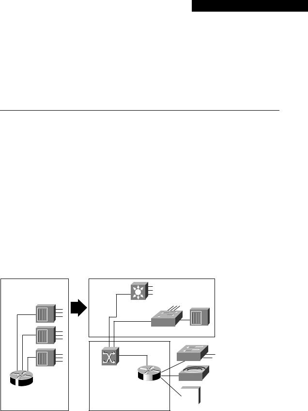
In the past, network designers had only a limited number of hardware options when purchasing a technology for their campus networks. Hubs were for wiring closets and routers were for the data center or main telecommunications operations. The increasing power of desktop processors and the requirements of client-server and multimedia applications, however, have driven the need for greater bandwidth in traditional shared-media environments. These requirements are prompting network designers to replace hubs in their wiring closets with switches, as shown in Figure 12–1.
Figure 12-1 Evolution from shared to switched internetworks.
Traditional wiring closet
Shared hub

 Router


Cisco router
Traditional backbone
The new wiring closet
 Si
Si 
Multilayer switch (Layers 2 and 3)
LAN switch (Layer 2) |
Hub |
ATM campus |
|
|
|
|
|
|
|
|
CDDI/FDDI |
|
|
|
|
|
|
|
|
|
|||
switch |
|
Router |
|
|
|
|
|
|
concentrator |
|
|
|
Cisco router |
|
|
|
|
|
|
||
The new backbone |
|
|
|
|
|
|
||||
|
|
|
|
|
|
|||||
|
|
|
|
|
|
|||||
|
|
|
|
|
|
|||||
|
|
|
|
|
|
|||||
Shared hub |
||||||||||
|
|
|
|
|||||||
This strategy allows network managers to protect their existing wiring investments and boost network performance with dedicated bandwidth to the desktop for each user. Coinciding with the wiring closet evolution is a similar trend in the network backbone. Here, the role of Asynchronous
Designing Switched LAN Internetworks 12-1

Technologies for Building Switched LAN Internetworks
Transfer Mode (ATM) is increasing as a result of standardizing protocols, such as LAN emulation (LANE), that enable ATM devices to coexist with existing LAN technologies. Network designers are collapsing their router backbones with ATM switches, which offer the greater backbone bandwidth required by high-throughput data services.
Technologies for Building Switched LAN Internetworks
With the advent of such technologies as Layer 3 switching, LAN switching, and VLANs, building campus LANs is becoming more complex than in the past. Today, the following three technologies are required to build successful campus networks:
•LAN switching technologies
—Ethernet switching—Provides Layer 2 switching and offers broadcast domain segmentation using VLANs. This is the base fabric of the network.
—Token Ring switching— Offers the same functionality as Ethernet switching but uses Token Ring technology. You can use a Token Ring switch as either a transparent bridge or source-route bridge.
—Copper Data Distributed Interface (CDDI)— Provides a single-attachment station (SAS) or dual-attachment station (DAS) to two Category 5 unshielded twisted-pair (UTP), 100 Mbps RJ-45 connectors.
—Fiber Distributed Data Interface (FDDI)— Provides an SAS or DAS connection to the FDDI backbone network using two multimode, media interface connector (MIC) fiberoptic connections.
•ATM switching technologies
ATM switching offers high-speed switching technology for voice, video, and data. Its operation is similar to LAN switching technologies for data operations. ATM, however, offers superior voice, video, and data integration today.
• Routing technologies
Routing is a key technology for connecting LANs in a campus network. It can be either Layer 3 switching or more traditional routing with Layer 3 switching features and enhanced Layer 3 software features.
Note Switched LAN internetworks are also referred to as campus LANs.
Role of LAN Switching Technology in Campus Networks
Most network designers are beginning to integrate switching devices into their existing sharedmedia networks to achieve the following goals:
•Increase the bandwidth that is available to each user, thereby alleviating congestion in their shared-media networks.
•Employ the manageability of VLANs by organizing network users into logical workgroups that are independent of the physical topology of wiring closet hubs. This, in turn, can reduce the cost of moves, adds, and changes while increasing the flexibility of the network.
•Deploy emerging multimedia applications across different switching platforms and technologies, making them available to a variety of users.
12-2 Cisco CCIE Fundamentals: Network Design

Switched Internetwork Solutions
•Provide a smooth evolution path to high-performance switching solutions, such as Fast Ethernet and ATM.
Segmenting shared-media LANs divides the users into two or more separate LAN segments, reducing the number of users contending for bandwidth. LAN switching technology, which builds upon this trend, employs microsegmentation, which further segments the LAN to fewer users and ultimately to a single user with a dedicated LAN segment. Each switch port provides a dedicated, 10MB Ethernet segment, or dedicated 4/16MB Token Ring segment.
Segments are interconnected by internetworking devices that enable communication between LANs while blocking other types of traffic. Switches have the intelligence to monitor traffic and compile address tables, which then allows them to forward packets directly to specific ports in the LAN. Switches also usually provide nonblocking service, which allows multiple conversations (traffic between two ports) to occur simultaneously.
Switching technology is quickly becoming the preferred solution for improving LAN traffic for the following reasons:
•Unlike hubs and repeaters, switches allow multiple data streams to pass simultaneously.
•Switches have the capability through microsegmentation to support the increased speed and bandwidth requirements of emerging technologies.
•Switches deliver dedicated bandwidth to users through high-density group switched and switched 10BaseT or 100BaseT Ethernet, flexible 10/100 BaseT Ethernet, fiber-based Fast Ethernet, Fast EtherChannel, Token Ring, CDDI/FDDI, and ATM LAN Emulation (LANE).
Switched Internetwork Solutions
Network designers are discovering, however, that many products offered as switched internetwork solutions are inadequate. Some offer a limited number of hardware platforms with little or no system integration with the current infrastructure. Others require complete abandonment of all investments in the current network infrastructure. To be successful, a switched internetwork solution must accomplish the following:
•Leverage strategic investments in the existing communications infrastructure while increasing available bandwidth.
•
•
Reduce the costs of managing network operations.
Offer options to support multimedia applications and other high-demand traffic across a variety of platforms.
•Provide scalability, traffic control, and security that is at least as good or better than that of today’s router-based internetworks.
•Provide support for embedded remote monitoring (RMON) agent.
The key to achieving these benefits is to understand the role of the internetworking software infrastructure within the switched internetworks. Within today’s networks, routers allow for the interconnection of disparate LAN and WAN technologies, while also implementing security filters and logical firewalls. It is these capabilities that have allowed current internetworks to scale globally while remaining stable and robust.
As networks evolve toward switched internetworks, similar logical internetworking capabilities are required for stability and scalability. Although LAN and ATM switches provide great performance improvements, they also raise new internetworking challenges. Switched internetworks must integrate with existing LAN and WAN networks. Such services as VLANs, which will be deployed with switched internetworks, also have particular internetworking requirements.
Designing Switched LAN Internetworks 12-3

Components of the Switched Internetworking Model
A true switched internetwork, therefore, is more than a collection of boxes. Rather, it consists of a system of devices integrated and supported by an intelligent internetworking software infrastructure. Presently, this network intelligence is centralized within routers. However, with the advent of switched internetworks, the intelligence will often be dispersed throughout the network, reflecting the decentralized nature of switching systems. The need for an internetworking infrastructure, however, will remain.
Components of the Switched Internetworking Model
A switched internetwork is composed of the following three basic components:
•
•
•
Physical switching platforms
A common software infrastructure
Network management tools and applications
Cisco provides network designers with a complete, end-to-end solution for implementing and managing scalable, robust, switched internetworks.
Scalable Switching Platforms
The first component of the switched internetworking model is the physical switching platform. This can be an ATM switch, a LAN switch, or a router.
ATM Switches
Although switched internetworks can be built with a variety of technologies, many network designers will deploy ATM in order to utilize its unique characteristics. ATM provides scalable bandwidth that spans both LANs and WANs. It also promises Quality of Service (QoS) guarantees—bandwidth on demand—that can map into and support higher-level protocol infrastructures for emerging multimedia applications and provide a common, multiservice network infrastructure.
ATM switches are one of the key components of ATM technology. All ATM switches, however, are not alike. Even though all ATM switches perform cell relay, ATM switches differ markedly in the following capabilities:
•
•
•
•
•
•
Variety of interfaces and services that are supported
Redundancy
Depth of ATM internetworking software
Sophistication of traffic management mechanism
Blocking and non-blocking switching fabrics
SVC and PVC support
Just as there are routers and LAN switches available at various price/performance points with different levels of functionality, ATM switches can be segmented into the following four distinct types that reflect the needs of particular applications and markets:
•
•
•
Workgroup ATM switches
Campus ATM switches
Enterprise ATM switches
12-4 Cisco CCIE Fundamentals: Network Design
Scalable Switching Platforms
• Multiservice access switches
As Figure 12–2 shows, Cisco offers a complete range of ATM switches.
Figure 12-2 Different types of ATM switches.
LightStream 1010 |
LightStream 1010 |
Catalyst |
|
LAN |
|
switches |
|
LightStream |
LightStream |
1010 |
1010 |
StrataCom |
Service multiplexer |
|
|
LightStream |
|
1010 |
|

 Router

Cisco routers
Workgroup ATM
Campus ATM
Enterprise ATM
Multiservice Access ATM
WAN
StrataCom
Workgroup and Campus ATM Switches
Workgroup ATM switches are optimized for deploying ATM to the desktop over low-cost ATM desktop interfaces, with ATM signaling interoperability for ATM adapters and QoS support for multimedia applications.
Campus ATM switches are generally used for small-scale ATM backbones (for example, to link ATM routers or LAN switches). This use of ATM switches can alleviate current backbone congestion while enabling the deployment of such new services as VLANs. Campus switches need to support a wide variety of both local backbone and WAN types but be price/performance optimized for the local backbone function. In this class of switches, ATM routing capabilities that allow multiple switches to be tied together is very important. Congestion control mechanisms for optimizing backbone performance is also important.
Enterprise ATM Switches
Enterprise ATM switches are sophisticated multiservice devices that are designed to form the core backbones of large, enterprise networks. They are intended to complement the role played by today’s high-end multiprotocol routers. Enterprise ATM switches, much as campus ATM switches, are used to interconnect workgroup ATM switches and other ATM-connected devices, such as LAN switches. Enterprise-class switches, however, can act not only as ATM backbones but can serve as the single point of integration for all of the disparate services and technology found in enterprise backbones
Designing Switched LAN Internetworks 12-5

Components of the Switched Internetworking Model
today. By integrating all of these services onto a common platform and a common ATM transport infrastructure, network designers can gain greater manageability while eliminating the need for multiple overlay networks.
LAN Switches
A LAN switch is a device that typically consists of many ports that connect LAN segments (Ethernet and Token Ring) and a high-speed port (such as 100-Mbps Ethernet, Fiber Distributed Data Interface [FDDI], or 155-Mbps ATM). The high-speed port, in turn, connects the LAN switch to other devices in the network.
A LAN switch has dedicated bandwidth per port, and each port represents a different segment. For best performance, network designers often assign just one host to a port, giving that host dedicated bandwidth of 10 Mbps, as shown in Figure 12–3, or 16 Mbps for Token Ring networks.
Figure 12-3 Sample LAN switch configuration.
Host A
Host B
|
|
|
|
|
|
|
|
|
|
|
|
|
|
|
|
|
Ethernet |
|
|
|
Port 1 |
High-speed port |
|||||
|
|
|
|
|
|
|
|
|
|
|
|
|
|
|
|
|
|
|
|
||||||||
|
|
|
|
|
|
|
|
|
|
|
|
|
|
|
|
|
|
|
|
||||||||
|
|
|
|
|
|
|
|
|
|
|
|
|
|
|
|
|
|
|
|
||||||||
|
|
|
|
|
|
|
|
|
|
|
|
|
|
|
|
|
Ethernet |
Port 2 |
|
|
|
||||||
|
|
|
|
|
|
|
|
|
|
|
|
|
|
|
|
|
|
|
|
||||||||
|
|
|
|
|
|
|
|
|
|
|
|
|
|
|
|
|
|
|
|
||||||||
|
|
|
|
|
|
|
|
|
|
|
|
|
|
|
|
|
Ethernet |
|
|
|
|
|
|
|
|
|
|
|
|
|
|
|
|
|
|
|
|
|
|
|
|
|
|
|
|
|
|
|
|
|
|
|
|
|
|
|
|
|
|
|
|
|
|
|
|
|
|
|
|
|
|
|
Ethernet |
Port 3 |
|
|
|
|
|
|
|||
|
|
|
|
|
|
|
|
|
|
|
|
|
|
|
|
|
|
|
|
|
|
||||||
|
|
|
|
|
|
|
|
|
|
|
|
|
|
|
|
|
|
|
|
|
|
|
|
|
|
|
|
|
|
|
|
|
|
|
|
|
|
|
|
|
|
|
|
|
|
|
|
|
|
|
|
|
|
|
|
|
|
|
|
|
|
|
|
|
|
|
|
|
|
|
|
|
|
Port 4 |
|
|
|
|
|||||
|
|
|
|
|
|
|
|
|
|
|
|
|
|
|
|
|
|
|
Port n |
|
|
|
|||||
|
|
|
|
|
|
|
|
|
|
|
|
|
|
|
|
|
|
|
|
|
|||||||
Host C
Host D
When a LAN switch first starts up and as the devices that are connected to it request services from other devices, the switch builds a table that associates the MAC address of each local device with the port number through which that device is reachable. That way, when Host A on Port 1 needs to transmit to Host B on Port 2, the LAN switch forwards frames from Port 1 to Port 2, thus sparing other hosts on Port 3 from responding to frames destined for Host B. If Host C needs to send data to Host D at the same time that Host A sends data to Host B, it can do so because the LAN switch can forward frames from Port 3 to Port 4 at the same time it forwards frames from Port 1 to Port 2.
Whenever a device connected to the LAN switch sends a packet to an address that is not in the LAN switch’s table (for example, to a device that is beyond the LAN switch), or whenever the device sends a broadcast or multicast packet, the LAN switch sends the packet out all ports (except for the port from which the packet originated)—a technique known as flooding .
Because they work like traditional “transparent” bridges, LAN switches dissolve previously well-defined workgroup or department boundaries. A network built and designed only with LAN switches appears as a flat network topology consisting of a single broadcast domain. Consequently, these networks are liable to suffer the problems inherent in flat (or bridged) networks—that is, they do not scale well. Note, however, that LAN switches that support VLANs are more scalable than traditional bridges.
Multiservice Access Switches
Beyond private networks, ATM platforms will also be widely deployed by service providers both as customer premises equipment (CPE) and within public networks. Such equipment will be used to support multiple MAN and WAN services—for example, Frame Relay switching, LAN
12-6 Cisco CCIE Fundamentals: Network Design

Common Software Infrastructure
interconnect, or public ATM services—on a common ATM infrastructure. Enterprise ATM switches will often be used in these public network applications because of their emphasis on high availability and redundancy, and their support of multiple interfaces.
Routing Platforms
In addition to LAN switches and ATM switches, typically network designers use routers as one of the components in a switched internetwork infrastructure. While LAN switches are being added to wiring closets to increase bandwidth and to reduce congestion in existing shared-media hubs, high-speed backbone technologies, such as ATM switching and ATM routers are being deployed in the backbone. Within a switched internetwork, routing platforms also allow for the interconnection of disparate LAN and WAN technologies while also implementing broadcast filters and logical firewalls. In general, if you need advanced internetworking services, such as broadcast firewalling and communication between dissimilar LANs, routers are necessary.
Common Software Infrastructure
The second level of a switched internetworking model is a common software infrastructure. The function of this software infrastructure is to unify the variety of physical switching platforms: LAN switches, ATM switches, and multiprotocol routers. Specifically, the software infrastructure should perform the following tasks:
•
•
•
•
Monitor the logical topology of the network
Logically route traffic
Manage and control sensitive traffic
Provide firewalls, gateways, filtering, and protocol translation
Cisco offers network designers Cisco Internetwork Operating System (Cisco IOS) switching software. This subset of the Cisco IOS software is optimized for switching and provides the unifying element to Cisco’s line of switching platforms in a switched internetwork. The Cisco IOS software is found on standalone routers, router modules for shared-media hubs, PC and workstations file servers, multiservice WAN access switches, LAN switches, ATM switches, and ATM-capable PBXs. It provides optional levels of routing and switching across a switched internetwork in addition to new capabilities, such as VLANs, ATM internetworking software services, multilayer switching, extensions to support new networked multimedia applications, and traffic management and analysis tools.
VLANs
A VLAN consists of several end systems, either hosts or network equipment (such as switches and routers), all of which are members of a single logical broadcast domain. A VLAN no longer has physical proximity constraints for the broadcast domain. This VLAN is supported on various pieces of network equipment (for example, LAN switches) that support VLAN trunking protocols between them. Each VLAN supports a separate Spanning Tree (IEEE 802.1d).
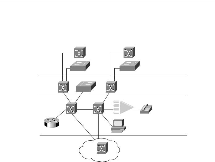
First-generation VLANs are based on various OSI Layer 2 bridging and multiplexing mechanisms, such as IEEE 802.10, LAN Emulation (LANE), and Inter-Switch Link (ISL), that allow the formation of multiple, disjointed, overlaid broadcast groups on a single network infrastructure. Figure 12-4 shows an example of a switched LAN network that uses VLANs. Layer 2 of the OSI reference model provides reliable transit of data across a physical link. The data link layer is concerned with physical addressing, network topology, line discipline, error notification, ordered delivery frames, and flow control. The IEEE has divided this layer into two sublayers: the MAC sublayer and the LLC sublayer, sometimes simply called link layer.
Designing Switched LAN Internetworks 12-7

Components of the Switched Internetworking Model
Figure 12-4 Typical VLAN topology.
Sixth floor |
10 Mbps |
|
VLAN 20 |
|
|
|
|
1 |
|
|
8 |
VLAN 10 |
|
Switch A |
|
10 Mbps |
|
Fifth floor |
6 |
|
|
|
|
VLAN 10 |
|
|
10 Mbps
|
|
|
Fourth floor |
|
|
|
|
|
|
|
|
|
|
|
|
|
|
|
|
|
100 Mbps |
||||||||||||
VLAN 20 |
|
|
|
|
|
|
|
|
|
|
|
|
|
|
|
|
|
|
|
|
1 2 |
|
Switch B |
|
|
|
|||||||
|
|
|
|
|
|
|
|
|
|
|
|
|
|
|
|
|
|
|
|
|
|
|
|||||||||||
|
|
|
|
|
|
|
|
|
|
|
|
|
|
|
|
|
|
|
|
|
|
|
|||||||||||
|
|
|
|
|
|
|
|
|
|
|
|
|
|
|
|
|
|
|
|||||||||||||||
|
|
|
|
|
|
|
|
|
|
|
|
||||||||||||||||||||||
|
|
|
|
|
|
|
|
|
|
|
|
|
|
|
|
|
|
|
|
|
|
|
|
|
|
|
|
|
|||||
|
|
|
|
|
|
|
|
|
|
|
|
|
|
|
|
|
|
|
|
|
|
|
|
|
|
|
|
|
|||||
|
|
|
|
|
|
|
|
|
|
|
|
|
|
|
|
|
|
|
|
|
|
|
|
|
|
|
|
|
|||||
VLAN 10 |
|
|
10 Mbps |
|
|
|
|
|
|
|
|
|
|
|
|
||||||||||||||||||
|
|
|
|
|
|
|
|
|
|
|
|
||||||||||||||||||||||
|
|
|
|
|
|
|
|
|
|
|
|
||||||||||||||||||||||
|
|
|
|
|
|
|
|
|
|
|
|
|
|
|
|
|
|
|
|
|
|
|
|
|
|
||||||||
|
|
|
Third floor |
3 |
|
|
|
|
100 Mbps |
||||||||||||||||||||||||
|
|
|
|
|
|
|
|
|
|
|
|
|
|
|
|||||||||||||||||||
VLAN 20 |
|
|
|
|
|
|
|
|
|
|
|
|
|
|
|
|
|
||||||||||||||||
|
|
|
|
|
|
|
|
|
|
|
|
|
|
|
|
|
|
|
|
||||||||||||||
|
|
|
|
|
|
|
|
|
|
|
|
|
|
|
|
|
|
|
|
|
|
|
|
|
|
|
|
Switch C |
2/2 |
||||
|
|
|
|
|
|
|
|
|
|
|
|
|
|
|
|
|
|
|
|
|
|
|
|
|
|
|
|
||||||
|
|
|
|
|
|
|
|
|
|
|
|
|
|
|
|
|
|
|
|
|
|
|
|
|
|
|
|
||||||
|
|
|
|
|
|
|
|
|
|
|
|
|
|
|
|
|
|
|
|
|
|
|
|
|
|
|
|
|
|
|
100 Mbps |
|
|
|
|
|
|
|
|
|
|
|
|
|
|
|
|
|
|
|
|
|
|
|
|
|
|
|
|
|
|
|
|
|
|
|
|
|
|
|
|
|
|
|
|
|
|
|
|
|
|
|
|
|
|
|
|
|
|
|
|
|
|
|
|
|
|
|
|
|
|
|
|
|
|
|
|
|
|
|
|
|
|
|
|
|
|
|
|
|
|
|
|
|
|
|
|
|
|
|
|
|
|
|
|
|
|
|
|
|
|
|
|
|
|
|
|
|
|
10 Mbps |
|
|
|
|
|
|
|
|
|
|
|
||||||||
|
|
|
Second floor |
|
|
|
|
|
|
|
|
|
Switch E |
||||||||||||||||||||
|
|
|
|
|
|
|
|
|
|
|
|
|
|||||||||||||||||||||
|
|
|
|
|
|
|
|
|
|
|
|
|
|
|
|
|
|
|
|
|
|||||||||||||
|
|
|
|
|
|
|
|
|
|
|
|
|
|
|
|
|
|
|
|
|
|
|
|||||||||||
|
|
|
|
|
|
|
|
|
|
|
|
|
|
|
|
|
|
|
|
|
|
|
|
|
|
|
|
Switch D |
100 Mbps |
||||
|
|
|
|
|
|
|
|
|
|
|
|
|
|
|
|
|
|
|
|
|
|
|
|
|
|
|
|
||||||
|
|
|
|
|
|
|
|
|
|
|
|
|
|
|
|
|
|
|
|
|
|
|
|
|
|
|
|
||||||
|
|
|
|
|
|
|
|
|
|
|
|
|
|
|
|
|
|
|
|
|
|
|
|
|
|
|
|
|
|
|
|
|
|
|
|
|
|
|
|
|
|
|
|
|
|
|
|
|
|
|
|
|
|
|
|
|
|
|
|
|
|
|
|
|
|
|
|
|
|
|
|
|
|
|
|
|
|
|
|
|
|
|
|
|
|
|
|
|
|
|
|
|
|
|
|
|
|
|
|
|
|
|
|
|
|
|
|
|
|
|
|
|
|
|
|
|
|
|
|
|
|
|
|
|
|
|
|
|
|
|
|
|
|
|
|
10 Mbps
First floor
In Figure 12-4, 10-Mbps Ethernet connects the hosts on each floor to switches A, B, C, and D. 100-Mbps Fast Ethernet connects these to Switch E. VLAN 10 consists of those hosts on Ports 6 and 8 of Switch A and Port 2 on Switch B. VLAN 20 consists of those hosts that are on Port 1 of Switch A and Ports 1 and 3 of Switch B.
VLANs can be used to group a set of related users, regardless of their physical connectivity. They can be located across a campus environment or even across geographically dispersed locations. The users might be assigned to a VLAN because they belong to the same department or functional team, or because data flow patterns among them is such that it makes sense to group them together. Note, however, that without a router, hosts in one VLAN cannot communicate with hosts in another VLAN.
Network Management Tools and Applications
The third and last component of a switched internetworking model consists of network management tools and applications. As switching is integrated throughout the network, network management becomes crucial at both the workgroup and backbone levels. Managing a switch-based network requires a radically different approach than managing traditional hub and router-based LANs.
12-8 Cisco CCIE Fundamentals: Network Design