

Cisco. Fundamentals Network Design - Cisco Press
.pdfSummary
Figure 12-16 |
Distributed routing/switching design. |
|
|
|
||
Core |
|
|
Switch |
|
|
Switch |
|
|
|
|
|
||
|
155 Mbps |
|
|
100 Mbps |
|
|
Distribution |
|
|
|
|
|
|
|
Router |
Router |
Router |
Router |
Router |
Router |
100 Mbps |
|
|
100 Mbps |
|
|
|
Access |
|
|
|
|
|
|
|
|
|
Switches |
|
|
Switches |
10-Mbps Ethernet or 16-Mbps Token Ring
The distributed routing/switching design follows the classic hierarchical network model both physically and logically. Because it provides high bandwidth for access to routing functionality, this design scales very well. This design is optimized for networks that do not have the 80/20 pattern rule. If servers are centralized, most traffic is inter-VLAN; therefore, high routing content is needed.
Summary
Campus LAN designs use switches to replace traditional hubs and use an appropriate mix of routers to minimize broadcast radiation. With the appropriate pieces of software and hardware in place, and adhering to good network design, it is possible to build topologies, such as the examples described in the section “Switched LAN Network Designs” earlier in this chapter.
Designing Switched LAN Internetworks 12-29

Summary
12-30 Cisco CCIE Fundamentals: Network Design

C H A P T E R 1 3
Designing Internetworks for Multimedia
Networked multimedia applications are rapidly being deployed in campus LAN and WAN environments. From the corporate perspective, network multimedia applications, such as network TV or videoconferencing, hold tremendous promise as the next generation of productivity tools. The use of digital audio and video across corporate network infrastructures has tremendous potential for internal and external applications. The World Wide Web is a good example of network multimedia and its manifold capabilities.
More than 85 percent of personal computers sold are multimedia capable. This hardware revolution has initiated a software revolution that has brought a wide range of audioand video-based applications to the desktop. It is not uncommon for computers to run video editing or image processing applications (such as Adobe Premiere and Photoshop) in addition to basic “productivity” applications (word processing, spreadsheet, and database applications).
The proliferation of multimedia-enabled desktop machines has spawned a new class of multimedia applications that operate in network environments. These network multimedia applications leverage the existing network infrastructure to deliver video and audio applications to end users, such as videoconferencing and video server applications. With these application types, video and audio streams are transferred over the network between peers or between clients and servers.
To successfully deliver multimedia over a network, it is important to understand both multimedia and networking. Three components must be considered when deploying network multimedia applications in campus LAN and WAN environments:
•Bandwidth—How much bandwidth do the network multimedia applications demand and how much bandwidth can the network infrastructure provide?
•Quality of service—What level of service does the network multimedia application require and how can this be satisfied through the network?
•Multicasting—Does the network multimedia application utilize bandwidth-saving multicasting techniques and how can multicasting be supported across the network?
This chapter addresses the underpinnings of effectively deploying network multimedia applications. Specifically, this chapter addresses the following topics:
•Multimedia Basics, including analog video, digital video, video compression, and digital audio standards
•Using Networked Multimedia Applications, including bandwidth and quality of service requirements
•Understanding Multicasting, including Internet Group Management Protocol, Distance Vector Multicast Routing Protocol, Multicast Open Shortest Path First, Protocol Independent Multicast, and Simple Multicast Routing Protocol
Designing Internetworks for Multimedia 13-1

Multimedia Basics
•Network Designs for Multimedia Applications, including traditional LAN designs, WAN designs, and high-speed LAN designs
Multimedia Basics
Much of today’s video starts out as an analog signal, so a working knowledge of analog standards and formats is essential for understanding digital video and the digitization process. The following topics are fundamental for understanding analog video:
•
•
•
•
•
Broadcast Standards
Video Signal Standards
Video Storage Formats
Digitizing Video
Digitizing Audio
Broadcast Standards
The principal standards for analog broadcast transmission are as follows:
•National Television Standards Committee (NTSC)—The broadcast standard in Canada, Japan, the United States, and Central America. NTSC defines 525 vertical scan lines per frame and yields 30 frames per second. The scan lines refer to the number of lines from top to bottom on the television screen. The frames per second refer to the number of complete images that are displayed per second.
•Phase Alternation Line (PAL)—The broadcast standard in Europe and in the Middle East, Africa, and South America. PAL defines 625 vertical scan lines and refreshes the screen 25 times per second.
•Système Electronique pour Couleur Avec Mémoire (SECAM) —The broadcast standard in France, Russia, and regions of Africa. SECAM is a variant of PAL but it delivers the same number of vertical scan lines as PAL and uses the same refresh rate.
To produce an image on a television screen, an electron gun scans across the television screen from left to right moving from top to bottom, as shown in Figure 13-1.
Figure 13-1 Television scan gun operation.
Electron gun
Electrons |
Screen 
Left to right
 Screen
Top to bottom
Side view |
Front view |
13-2 Cisco CCIE Fundamentals: Network Design

Video Signal Standards
Early television sets used a phosphor-coated tube, which meant that by the time the gun finished scanning all the lines that the broadcast standard required, the lines at the top were starting to fade. To combat fading, the NTSC adopted an interlace technique so that on the first pass from top to bottom, only every other line is scanned. With NTSC, this means that the first pass scans 262 lines. The second pass scans another 262 lines that are used to fill in the rest of the TV image.
A frame represents the combination of the two passes, known as fields , as Figure 13-2 indicates. For NTSC to deliver 30 frames per second, it must generate 60 fields per second. The rate at which fields are delivered depends on the clocking source. NTSC clocks its refresh intervals from AC power. In the United States, the AC power runs at 60 hertz or 60 oscillations per second. The 60 hertz yields 60 fields per second with every two fields yielding a frame. In Europe, AC power clocks at 50 hertz. This yields 50 fõelds per second or 25 frames per second.
Figure 13-2 Interlace scan process.
= 1st pass (1st field)
= 2nd pass (2nd field)
Video Signal Standards
Black-and-white televisions receive one signal called luminance (also know as the Y signal). Each screen pixel is defined as some range of intensity between white (total intensity) and black (no intensity). In 1953, the NTSC was faced with the task of revising their standard to handle color. To maintain compatibility with older black-and-white sets, the NTSC set a color standard that kept the luminance signal separate and that provided the color information required for newer color television sets.
In the digital world, colors are typically expressed using red, green, and blue (RGB). The analog world has also embraced the RGB standard, at least on the acquisition side, where most cameras break the analog signal into RGB components.
Unfortunately, the NTSC could not use RGB as the color television standard because the old black- and-white sets could not decode RGB signals. Instead, they had to send a luminance signal for black-and-white sets and fill in the color information with other signals, called hue and saturation, (also known as the U and V signals). For this reason, digital color technology uses RGB and analog color technology, especially broadcast television, uses YUV (Y, U, and V signals).
Figure 13-3 traces an analog video signal from capture to NTSC output. On the far left is the RGB capture in which storage channels are maintained for each of the three primary colors. RGB, however, is an inefficient analog video storage format for two reasons:
•First, to use RGB, all three color signals must have equal bandwidth in the system, which is often inefficient from a system design perspective.
•Second, because each pixel is the sum of red, green and blue values, modifying the pixel forces an adjustment of all three values. In contrast, when images are stored as luminance and color formats (that is, YUV format), a pixel can be altered by modifying only one value.
Designing Internetworks for Multimedia 13-3
Multimedia Basics
Figure 13-3 |
RGB to NTSC encoding. |
|
|
|
|
||||
|
|
|
Component |
Composite |
|
|
|
||
|
|
|
|
|
|
|
|
|
|
Red |
|
|
|
|
|
NTSC |
|
|
TV |
|
|
|
|
|
|
|
|||
|
|
|
|
|
|
|
|
||
|
|
|
|
|
|
|
|
||
Green |
|
|
|
|
|
|
|
||
|
|
|
|
|
encoding |
|
|
||
|
|
|
|
|
|
|
|
|
|
|
|
|
|
|
|
|
|
|
|
Blue |
|
|
|
|
|
|
|
|
|
|
|
|
|
|
|
|
|
|
|
|
|
|
|
|
|
|
|
|
|
|
|
|
|
|
|
|
|
|
|
NTSC output (8mm/VHS/LaserDisc)
Y |
U |
V |
|
|
Beta Sp |
Y |
C |
|
|
HI-8/S-VHS
Component video maintains separate channels for each color value, both in the recording device and the storage medium. Component video delivers the highest fidelity because it eliminates noise that would otherwise occur if two signals were combined in one channel.
After NTSC encoding, the hue and saturation channels (U and V signals) are combined into one chrominance channel, the C channel. A video signal, called S-Video, carries separate channels for the luminance and chrominance signals. S-Video is also known as Y/C video.
All color and other information must be combined into one YUV channel, called the composite signal, to play on old black-and-white televisions. Technically, a composite signal is any signal that contains all the information necessary to play video. In contrast, any one individual channel of component or Y/C video is not sufficient to play video.
A video signal can be transmitted as composite, S-Video, or component video. The type of video signal affects the connector that is used. The composite signal, which carries all the information in one electrical channel, uses a one-hole jack called the RCA Phono connector. The S-Video signal, composed of two electrical channels, uses a four-pin connector called the mini-DIN connector. Finally, the component signal uses three connectors.
Video Storage Formats
There are six video storage formats: 8 mm, Beta SP, HI-8, Laserdisc, Super VHS (SVHS), and VHS. The six formats use different signals to store color. The composite signal provides the lowest quality because all signals are combined, which in turn has the highest potential for noise. The S-Video signal produces less noise because the two signals are isolated in separate channels. The component signal provides the highest quality signal because all components are maintained in separate channels. The image quality that a video capture board produces can only be as good as the signal it accepts. Table 13-1 lists the analog capture and storage standards for video.
Table 13-1 |
Analog Video Storage Formats |
|
|
||
|
|
|
|
|
|
|
|
Beta SP |
SVHS/HI-8 |
VHS/8mm |
Laserdisc |
|
|
|
|
|
|
Color signal |
|
Component |
Y/C |
Composite |
Composite |
|
|
|
|
|
|
Lines of resolution |
|
750 |
400 |
200 |
400 |
|
|
|
|
|
|
Signal-to-noise ratio |
50 db |
47 db |
47 db |
47 db |
|
|
|
|
|
|
|
13-4 Cisco CCIE Fundamentals: Network Design
Digitizing Video
As Table indicates, the storage formats deliver different lines of resolution. Resolution is a measure of an image’s quality. From the viewer’s perspective, an image with higher resolution yields sharper picture quality than a lower resolution image.
Most consumer televisions display roughly 330 lines of horizontal resolution. Broadcast environments typically used high-end cameras to capture video. These cameras and their associated storage formats can deliver horizontal resolutions of approximately 700 lines. Each time a copy is made, the copied image loses some of its resolution. When an image is recorded in high-resolution, multiple generations of the video can be copied without a noticeable difference. When an image is recorded in a lower resolution, there is less room to manipulate the image before the viewer notices the effects.
Digitizing Video
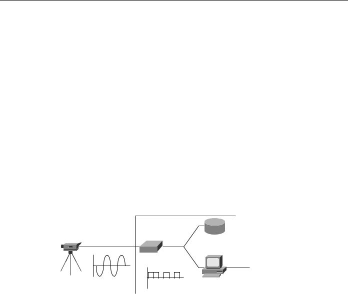
Digitizing video involves taking an analog video signal and converting it to a digital video stream using a video capture board, as shown in Figure 13-4. Today, a variety of computer platforms, including PC, Macintosh, and UNIX workstations, offer video capture capabilities. In some cases, though, the capture equipment is a third-party add-on. The analog video source can be stored in any video storage format or it can be a live video feed from a camera. The source can be connected to the video capture card using any three connectors types (component, S-Video, or composite) depending on the connector type that the card supports.]
Figure 13-4 Analog-to-digital video conversion.
PC or Macintosh
Storage
Digitizer
Ethernet
TV camera
Analog
video
Digital video at
27 MBps
When capturing and digitizing video, the following components are critical:
•Resolution—The horizontal and vertical dimensions of the video session. A full-screen video session is typically 640 horizontal pixels by 480 vertical pixels. Full-screen video uses these dimensions because it yields the 4:3 aspect ratio of standard television. Of the 525 vertical scan lines in the NTSC standard, 483 lines are used to display video. The other lines are used for signaling and are referred to as the vertical blanking interval. Because the NTSC standard uses 483 vertical lines, capturing at 640 by 480 means that three lines are dropped during the digitization process.
•Color depth—The number of bits that are used to express color. At the high end is 24-bit color, which is capable of displaying 16.7 million colors and is the aggregate of 8 bits of red, 8 bits of green, and 8 bits of blue. The 8 bits are used to express color intensity from 0 to 255. Other common color depths are 16-bit and 8-bit, which yield roughly 65,000 and 256 colors, respectively.
•Frame rate—The number of frames that are displayed per second. To deliver NTSC-quality video, 30 frames per second are displayed. PAL and SECAM display 25 frames per second.
Designing Internetworks for Multimedia 13-5

Multimedia Basics
Based on these criteria, it is a simple mathematical operation to determine how much bandwidth a particular video stream requires. For example, to deliver uncompressed NTSC-quality digitized video to the network, a bandwidth of approximately 27 megabytes per second (Mbps) is needed. This number is derived from the following calculation:
640 × 480 × 3 × 30 = 27.648 MBps (or 221.184 megabits per second [Mbps])
where 640 and 480 represent the resolution in pixels, 3 represents 24-bit color (3 bytes), and 30 represents the number of frames per second.
As this calculation indicates, full-motion, full-color digital video requires considerably more bandwidth than today’s typical packet-based network can support. Fortunately, two techniques reduce bandwidth consumption:
•
•
Video Capture Manipulation
Video Compression
Video Capture Manipulation
Manipulating video capture parameters involves changing resolution, color depth, and frame rate. To reduce bandwidth consumption, all three variables are often changed. For example, some multimedia applications capture video at 320 × 240 with 8-bit color and at a frame rate of 15 frames per second. With these parameters, bandwidth requirements drop to 9.216 Mbps. Although this level of bandwidth is difficult for a 10-Mbps Ethernet network to achieve, it can be provided by 16-Mbps Token Ring, 100-Mbps Fast Ethernet, and other higher-speed technologies.
Video Compression
Video compression is a process whereby a collection of algorithms and techniques replace the original pixel-related information with more compact mathematical descriptions. Decompression is the reverse process of decoding the mathematical descriptions back to pixels for display. At its best, video compression is transparent to the end user. The true measure of a video compression scheme is how little the end user notices its presence, or how effectively it can reduce video data rates without adversely affecting video quality. An example of post-digitization video compression is shown in Figure 13-5.
13-6 Cisco CCIE Fundamentals: Network Design

Digitizing Video
Figure 13-5 Post-digitization video compression.
|
|
|
|
|
|
|
|
|
|
|
|
|
|
|
atmSwitch(1) |
|
|
|
|
|
|
|
|
|
|
|
|
|
|
|
|
|
|||||||
|
|
|
|
|
|
|
|
|
|
|
|
|
|
|
|
|
|
|
|
|
|
|
|
|
|
|
|
|
|
|
|
|
|
|
|
|
|
||
|
|
|
|
|
|
|
|
|
|
|
|
|
|
|
|
|
|
|
|
|
|
|
|
|
|
|
|
|
|
|
|
|
|
|
|
|
|
|
|
|
|
|
|
|
|
|
|
|
|
|
|
|
|
|
|
|
|
|
|
|
|
|
|
|
|
|
|
|
|
|
|
|
|
|
|
|
|
|
|
|
|
|
|
|
|
|
|
|
|
|
|
|
|
|
portInfo(3) |
|
|
|
|
|
|
|
|
|
|
|
|
|
|
|
|
|
|||||||
|
|
|
|
|
|
|
|
|
|
|
|
|
|
|
|
|
|
|
|
|
|
|
|
|
|
|
|
|
|
|
|||||||||
|
|
|
|
|
|
|
|
|
|
|
|
|
|
|
|
|
|
|
|
|
|
|
|
|
|
|
|
|
|
|
|
|
|
|
|
|
|
|
|
|
|
|
|
|
|
|
|
|
|
|
|
|
|
|
|
|
|
|
|
|
|
|
|
|
|
|
|
|
|
|
|
|
|
|
|
|
|
|
|
|
|
|
portinfoTable(1) |
|
|
|
|
|
IsEtherTable(2) |
|
|
|
|
|
atmPortInfo(3) |
|
|
|
|||||||||||||||||||||
|
|
|
|
|
|
|
|
|
|
|
|
|
|
|
|
|
|
|
|
|
|
|
|
|
|
|
|
|
|
|
|
|
|
|
|
||||
|
|
|
|
|
|
|
|
|
|
|
|
|
|
|
|
|
|
|
|
|
|
|
|
|
|
|
|
|
|
|
|
|
|
|
|
||||
|
|
|
portinfoEntry(1) |
|
|
|
|
|
IsEtherEntry(1) |
|
|
|
|
|
|
|
|
|
|
|
|
|
|
|
|
||||||||||||||
|
|
|
|
|
|
|
|
|
|
|
|
|
|
|
|
|
|
|
|
|
|
|
|
|
|
|
|
|
|
|
|
|
|
|
|
|
|
|
|
|
|
|
|
|
|
|
|
|
|
|
|
|
|
|
|
|
|
|
|
|
|
|
|
|
|
|
|
|
|
|
|
|
|
|
|
|
|
|
|
|
|
|
|
|
|
|
portinfoIndex(1) |
|
|
|
|
|
IsEtherMediaType(1) |
|
|
|
|
|
|
|
|
|
|||||||||||||||||
|
|
|
|
|
|
|
|
|
|
|
|
|
|
|
|
|
|
|
|
|
|||||||||||||||||||
|
|
|
|
|
|
|
|
|
|
|
|
|
|
|
|
|
|
|
|
|
|
|
|
|
|
|
|
|
|
|
|
|
|
|
|
|
|
|
|
|
|
|
|
|
|
|
|
|
|
|
|
|
|
|
|
|
|
|
|
|
|
|
|
|
|
|
|
|
|
|
|
|
|
|
|||||
|
|
|
|
|
|
|
portinfoLineType(6) |
|
|
|
|
|
|
|
|
|
|
|
|
|
|
|
|
|
|
|
|
|
|
|
|
||||||||
|
|
|
|
|
|
|
|
|
|
|
|
|
|
|
|
|
|
|
|
|
|
|
|
|
|
|
|
|
|
|
|||||||||
|
|
|
|
|
|
|
|
|
|
|
|
|
|
|
|
|
|
|
|
|
|
|
|
|
|
|
|
|
|
|
|
|
|
|
|
|
|
|
|
|
|
|
|
|
|
|
|
|
|
|
|
|
|
|
|
|
|
|
|
|
|
|
|
|
|
|
|
|
|
|
|
|
|
|
|
|
|
|
|
|
|
|
|
|
|
|
|
|
|
|
|
|
|
|
|
|
|
|
|
|
|
|
|
|
|
|
|
|
|
|
|
|
|
|
|
|
|
|
|
atmPortNetPrefix- |
|
|
|
|
atmESITable(2) |
|
|
|
|
|
|
atmATMAddr- |
|
|
|
|
atmExternalATM- |
|
|||||||||||||||||||||
|
|
|
Table(1) |
|
|
|
|
|
|
|
|
|
|
Table(3) |
|
|
|
|
AddrTable(4) |
|
|||||||||||||||||||
|
|
|
|
|
|
|
|
|
|
|
|
|
|
|
|
|
|
|
|
|
|
|
|
|
|||||||||||||||
|
|
|
|
|
|
|
|
|
|
|
|
|
|
|
|
|
|
|
|
|
|
|
|
|
|
|
|
|
|
|
|
|
|
|
|
|
|
|
|
|
|
|
|
|
|
|
|
|
|
|
|
|
|
|
|
|
|
|
|
|
|
|
|
|
|
|
|
|
|
|
|
|
|
|
|
|
|||
atmPortNetPrefix- |
|
|
|
|
atmESIEntry(1) |
|
|
|
|
|
atmATMAddr- |
|
|
|
|
atmExternalATM- |
|
||||||||||||||||||||||
|
|
|
Entry(1) |
|
|
|
|
|
|
|
|
|
|
Entry(1) |
|
|
|
|
|
AddrEntry(1) |
|
|
|||||||||||||||||
|
|
|
|
|
|
|
|
|
|
|
|
|
|
|
|
|
|
|
|
|
|
|
|
|
|||||||||||||||
|
|
|
|
|
|
|
|
|
|
|
|
|
|
|
|
|
|
|
|
|
|
|
|
|
|
|
|
|
|
|
|
|
|
|
|
|
|
||
|
|
|
|
|
|
|
|
|
|
|
|
|
|
|
|
|
|
|
|
|
|
|
|
|
|
|
|
|
|
||||||||||
|
|
atmPortNetPrefix- |
|
|
|
atmESIIndex(1) |
|
|
|
|
atmATMAddr- |
|
|
|
|
atmExternalATM- |
|||||||||||||||||||||||
|
|
|
Index(1) |
|
|
|
|
|
|
|
Index(1) |
|
|
|
|
AddrIndex(1) |
|||||||||||||||||||||||
|
|
|
|
|
|
|
|
|
|
|
|||||||||||||||||||||||||||||
|
|
|
|
|
|
|
|
|
|
|
|
|
|
|
|
|
|
|
|
|
|
|
|||||||||||||||||
|
|
|
|
|
|
|
|
|
|
|
|
|
|
|
|
|
|
|
|
|
|
|
|
|
|
|
|
|
|
|
|
|
|||||||
|
|
|
|
|
|
|
|
|
|
|
|
|
|
|
|
|
|
|
|
|
|
|
|
|
|
|
|
|
|
|
|
||||||||
|
|
atmPortNetPrefix- |
|
|
|
|
atmESIValue(2) |
|
|
|
|
atmATMAddr- |
|
|
|
|
|
|
|
|
|
||||||||||||||||||
|
|
|
Value(2) |
|
|
|
|
|
|
|
|
Value(2) |
|
|
|
|
|
|
|
|
|
||||||||||||||||||
|
|
|
|
|
|
|
|
|
|
|
|
|
|
|
|
|
|
|
|
|
|
|
|
atmExternalATM- |
|||||||||||||||
|
|
|
|
|
|
|
|
|
|
|
|
|
|
|
|
|
|
|
|
|
|
|
|
|
|
|
|
|
|
|
|
|
|
|
|||||
|
|
|
|
|
|
|
|
|
|
|
|
|
|
|
|
|
|
|
|
|
|
|
|
|
|
|
|
|
|
|
|
|
|||||||
|
|
|
|
|
|
|
|
|
|
|
|
|
|
|
|
|
|
|
|
|
|
|
|
|
|
|
|
|
|
|
|
|
|
|
AddrStatus(8) |
||||
|
|
|
|
|
|
|
|
|
|
|
|
|
|
|
|
|
|
|
|
|
|
|
|
|
|
|
|
|
|
|
|
|
|
|
|
|
|
|
|
Video compression is performed using a CODEC (Coder/Decoder or Compressor/Decompressor). The CODEC, which can be implemented either in software or hardware, is responsible for taking a digital video stream and compressing it and for receiving a precompressed video stream and decompressing it. Although most PC, Macintosh, and UNIX video capture cards include the CODEC, capture and compression remain separate processes.
There are two types of compression techniques:
•Lossless—A compression technique that creates compressed files that decompress into exactly the same file as the original. Lossless compression is typically used for executables (applications) and data files for which any change in digital makeup renders the file useless. In general, lossless techniques identify and utilize patterns within files to describe the content more efficiently. This works well for files with significant redundancy, such as database or spreadsheet files. However, lossless compression typically yields only about 2:1 compression, which barely dents high-resolution uncompressed video files. Lossless compression is used by products such as STAC and Double Space to transparently expand hard drive capacity, and by products like PKZIP to pack more data onto floppy drives. STAC and another algorithm called Predictor are supported in the Cisco IOS software for data compression over analog and digital circuits.
•Lossy—Lossy compression, used primarily on still image and video image files, creates compressed files that decompress into images that look similar to the original but are different in digital makeup. This “loss” allows lossy compression to deliver from 2:1 to 300:1 compression.
Designing Internetworks for Multimedia 13-7

Multimedia Basics
Lossy compression cannot be used on files, such as executables, that when decompressed must match the original file. When lossy compression is used on a 24-bit image, it may decompress with a few changed pixels or altered color shades that cannot be detected by the human eye.
When used on video, the effect of lossy compression is further minimized because each image is displayed for only a fraction of a second (1/15 or 1/30 of a second, depending on the frame rate).
A wide range of lossy compression techniques is available for digital video. This simple rule applies to all of them: the higher the compression ratio, the higher the loss. As the loss increases, so does the number of artifacts. (An artifact is a portion of a video image for which there is little or no information.)
In addition to lossy compression techniques, video compression involves the use of two other compression techniques:
• Interframe compression—Compression between frames (also known as temporal compression because the compression is applied along the time dimension).
• Intraframe compression—Compression within individual frames (also known as spatial compression).
Some video compression algorithms use both interframe and intraframe compression. For example, Motion Picture Experts Group (MPEG) uses Joint Photographic Experts Group (JPEG), which is an intrafame technique, and a separate interframe algorithm. Motion-JPEG (M-JPEG) uses only intraframe compression.
Interframe Compression
Interframe compression uses a system of key and delta frames to eliminate redundant information between frames. Key frames store an entire frame, and delta frames record only changes. Some implementations compress the key frames, and others don’t. Either way, the key frames serve as a reference source for delta frames. Delta frames contain only pixels that are different from the key frame or from the immediately preceding delta frame. During decompression, delta frames look back to their respective reference frames to fill in missing information.
Different compression techniques use different sequences of key and delta frames. For example, most video for Windows CODECs calculate interframe differences between sequential delta frames during compression. In this case, only the first delta frame relates to the key frame. Each subsequent delta frame relates to the immediately preceding delta frame. In other compression schemes, such as MPEG, all delta frames relate to the preceding key frame.
All interframe compression techniques derive their effectiveness from interframe redundancy. Low-motion video sequences, such as the head and shoulders of a person, have a high degree of redundancy, which limits the amount of compression required to reduce the video to the target bandwidth.
Until recently, interframe compression has addressed only pixel blocks that remained static between the delta and the key frame. Some new CODECs increase compression by tracking moving blocks of pixels from frame to frame. This technique is called motion compensation (also known as dynamic carry forwards) because the data that is carried forward from key frames is dynamic. Consider a video clip in which a person is waving an arm. If only static pixels are tracked between frames, no interframe compression occurs with respect to the moving parts of the person because those parts are not located in the same pixel blocks in both frames. If the CODEC can track the motion of the arm, the delta frame description tells the decompressor to look for particular moving parts in other pixel blocks, essentially tracking the moving part as it moves from one pixel block to another.
Although dynamic carry forwards are helpful, they cannot always be implemented. In many cases, the capture board cannot scale resolution and frame rate, digitize, and hunt for dynamic carry forwards at the same time.
13-8 Cisco CCIE Fundamentals: Network Design