

Cisco. Fundamentals Network Design - Cisco Press
.pdfTypes of Switches
•
•
Multiprotocol routing backbone
Single-protocol backbone
The following discussions outline the characteristics and properties of these two strategies.
Multiprotocol Routing Backbone
When multiple network layer protocols are routed throughout a common backbone without encapsulation (also referred to as native mode routing), the environment is referred to as a multiprotocol routing backbone. A multiprotocol backbone environment can adopt one of two routing strategies, or both, depending on the routed protocol involved. The two strategies are generally referred to as the following:
•Integrated routing—Integrated routing involves the use of a single routing protocol (for example, a link state protocol) that determines the least cost path for different routed protocols.
•Ships in the night—The ships-in-the-night approach involves the use of a different routing protocol for each network protocol. For instance, some large-scale networks might feature multiple protocols in which Novell IPX traffic is routed using a proprietary version of the Routing Information Protocol (RIP), IP is routed with IGRP, and DECnet Phase V traffic is routed via ISO CLNS-compliant IS-IS.
Each of these network layer protocols is routed independently, with separate routing processes handling their traffic and separate paths calculated. Mixing routers within an internetwork that supports different combinations of multiple protocols can create a confusing situation, particularly for integrated routing. In general, integrated routing is easier to manage if all the routers attached to the integrated routing backbone support the same integrated routing scheme. Routes for other protocols can be calculated separately. As an alternative, you can use encapsulation to transmit traffic over routers that do not support a particular protocol.
Single-Protocol Backbone
With a single-protocol backbone, all routers are assumed to support a single routing protocol for a single network protocol. In this kind of routing environment, all other routing protocols are ignored. If multiple protocols are to be passed over the internetwork, unsupported protocols must be encapsulated within the supported protocol or they will be ignored by the routing nodes.
Why implement a single-protocol backbone? If relatively few other protocols are supported at a limited number of isolated locations, it is reasonable to implement a single protocol backbone. However, encapsulation does add overhead to traffic on the network. If multiple protocols are supported widely throughout a large internetwork, a multiprotocol backbone approach is likely to work better.
In general, you should support all the network layer protocols in an internetwork with a native routing solution and implement as few network layer protocols as possible.
Types of Switches
Switches can be categorized as follows:
•LAN switches—The switches within this category can be further divided into Layer 2 switches and multilayer switches.
•ATM switches—ATM switching and ATM routers offer greater backbone bandwidth required by high-throughput data services.
Internetworking Design Basics 2-35

Identifying and Selecting Internetworking Devices
Network managers are adding LAN switches to their wiring closets to augment bandwidth and reduce congestion in existing shared-media hubs while using new backbone technologies, such as Fast Ethernet and ATM.
LAN Switches
Today’s cost-effective, high-performance LAN switches offer network managers the following benefits:
•
•
•
Superior microsegmentation
Increased aggregate data forwarding
Increased bandwidth across the corporate backbone
LAN switches address end users’ bandwidth needs for wiring closet applications. By deploying switches rather than traditional shared hubs, network designers can increase performance and leverage the current investments in existing LAN media and adapters. These switches also offer functionality not previously available, such as VLANs, that provide the flexibility to use software to move, add, and change users across the network.
LAN switches are also suited to provide segment switching and scalable bandwidth within network data centers by delivering switched links to interconnect existing hubs in wiring closets, LAN switches, and server farms. Cisco provides the Catalyst family of multilayer switches for connecting multiple wiring closet switches or shared hubs into a backbone configuration.
ATM Switches
Even though all ATM switches perform cell relay, ATM switches differ markedly in the following capabilities:
•
•
•
•
Variety of interfaces and services that are supported
Redundancy
Depth of ATM internetworking software
Sophistication of traffic management mechanism
Just as there are routers and LAN switches available at various price/performance points with different levels of functionality, ATM switches can be segmented into the following four distinct types that reflect the needs of particular applications and markets:
•
•
•
•
Workgroup ATM switches
Campus ATM switches
Enterprise ATM switches
Multiservice access switches
Cisco offers a complete range of ATM switches.
Workgroup and Campus ATM Switches
Workgroup ATM switches have Ethernet switch ports and an ATM uplink to connect to a campus ATM switch. An example of a workgroup ATM switch is the Cisco Catalyst 5000.
Campus ATM switches are generally used for small-scale ATM backbones (for example, to link ATM routers or LAN switches). This use of ATM switches can alleviate current backbone congestion and enable the deployment of such new services as VLANs. Campus switches need to support a wide
2-36 Cisco CCIE Fundamentals: Network Design

Switches and Routers Compared
variety of both local backbone and WAN types, but be price/performance optimized for the local backbone function. In this class of switches, ATM routing capabilities that allow multiple switches to be tied together is very important. Congestion control mechanisms for optimizing backbone performance is also important. The LightStream 1010 family of ATM switches is an example of a campus ATM switch. For more information on deploying workgroup and campus ATM switches in your internetwork, see Chapter 12, “Designing Switched LAN Internetworks.”
Enterprise ATM Switches
Enterprise ATM switches are sophisticated multiservice devices that are designed to form the core backbones of large, enterprise networks. They are intended to complement the role played by today’s high-end multiprotocol routers. Enterprise ATM switches are used to interconnect campus ATM switches. Enterprise-class switches, however, can act not only as ATM backbones but can serve as the single point of integration for all of the disparate services and technology found in enterprise backbones today. By integrating all of these services onto a common platform and a common ATM transport infrastructure, network designers can gain greater manageability and eliminate the need for multiple overlay networks.
Cisco’s BPX/AXIS is a powerful broadband ATM switch designed to meet the demanding, high-traffic needs of a large private enterprise or public service provider. For more information on deploying enterprise ATM switches in your internetwork, see Chapter 8, “Designing ATM Internetworks.”
Multiservice Access Switches
Beyond private networks, ATM platforms will also be widely deployed by service providers both as customer premises equipment (CPE) and within public networks. Such equipment will be used to support multiple MAN and WAN services—for example, Frame Relay switching, LAN interconnect, or public ATM services—on a common ATM infrastructure. Enterprise ATM switches will often be used in these public network applications because of their emphasis on high availability and redundancy, their support of multiple interfaces, and capability to integrate voice and data.
Switches and Routers Compared
To highlight the differences between switches and routers, the following sections examine the different roles of these devices in the following situations:
•
•
Implementation of VLANs
Implementation of switched internetworks
Role of Switches and Routers in VLANs
VLANs address the following two problems:
•Scalability issues of a flat network topology
•Simplification of network management by facilitating network reconfigurations (moves and changes)
A VLAN consists of a single broadcast domain and solves the scalability problems of large flat networks by breaking a single broadcast domain into several smaller broadcast domains or VLANs. Virtual LANs offer easier moves and changes in a network design than traditional networks. LAN switches can be used to segment networks into logically defined virtual workgroups. This logical segmentation, commonly referred to as VLAN communication, offers a fundamental change in how
Internetworking Design Basics 2-37

Identifying and Selecting Internetworking Devices
LANs are designed, administered, and managed. Although logical segmentation provides substantial benefits in LAN administration, security, and management of network broadcast across the enterprise, there are many components of VLAN solutions that network designers should consider prior to large scale VLAN deployment.
Switches and routers each play an important role in VLAN design. Switches are the core device that controls individual VLANs while routers provide interVLAN communication, as shown in Figure 2-23.
Figure 2-23 Role of switches and routers in VLANs.
VLAN Group 1 |
VLAN Group 2 |
||||||||
|
|
|
|
|
|
|
|
|
|
|
|
|
|
|
|
|
|
|
|
|
|
|
|
|
|
|
|
|
|
Floor 3
Floor 2
Access control between VLANs
Floor 1
Switches remove the physical constraints imposed by a shared-hub architecture because they logically group users and ports across the enterprise. As a replacement for shared hubs, switches remove the physical barriers imposed within each wiring closet. Additionally, the role of the router evolves beyond the more traditional role of firewalls and broadcast suppression to policy-based control, broadcast management, and route processing and distribution. Equally as important, routers remain vital for switched architectures configured as VLANs because they provide the communication between VLANs. Routers also provide VLAN access to shared resources, such as servers and hosts. For more information on deploying VLANs, see Chapter 12, “Designing Switched LAN Internetworks.”
Examples of Campus Switched Internetwork Designs
A successful campus switched internetworking solution must combine the benefits of both routers and switches in every part of the network, as well as offer a flexible evolution path from shared-media networking to switched internetworks.
For example, incorporating switches in campus network designs will generally result in the following benefits:
•
•
•
•
High bandwidth
Improved performance
Low cost
Easy configuration
If you need advanced internetworking services, however, routers are necessary. Routers offer the following services:
2-38 Cisco CCIE Fundamentals: Network Design
Switches and Routers Compared
•
•
•
•
•
•
•
•
•
•
Broadcast firewalling
Hierarchical addressing
Communication between dissimilar LANs
Fast convergence
Policy routing
QoS routing
Security
Redundancy and load balancing
Traffic flow management
Multimedia group membership
Some of these router services will be offered by switches in the future. For example, support for multimedia often requires a protocol, such as Internet Group Management Protocol (IGMP), that allows workstations to join a group that receives multimedia multicast packets. In the future, Cisco will allow switches to participate in this process by using the Cisco Group Management Protocol (CGMP). One router will still be necessary, but you will not need a router in each department because CGMP switches can communicate with the router to determine if any of their attached users are part of a multicast group.
Switching and bridging sometimes can result in non-optimal routing of packets. This is because every packet must go through the root bridge of the spanning tree. When routers are used, the routing of packets can be controlled and designed for optimal paths. Cisco now provides support for improved routing and redundancy in switched environments by supporting one instance of the spanning tree per VLAN.
The following figures illustrate how network designers can use switches and routers to evolve their shared-media networks to switching internetworks. Typically, this evolution to a campus switched internetwork architecture will extend over four phases.
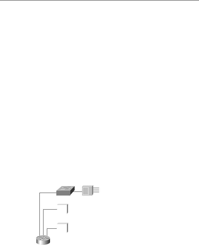
Phase 1 is the microsegmentation phase in which network designers retain their hubs and routers, but insert a LAN switch to enhance performance. Figure 2-24 shows an example of how a LAN switch can be used to segment a network.
Figure 2-24 Using switches for microsegmentation.
LAN switch |
Shared hub |
|||
|
|
|
|
|
|
|
|
|
|
|
|
|
|
|
|
|
|
|
|
|
|
|
|
|
|
|
|
|
|
|
|
|
|
|
|
|
|
|
|
|
|
|
|
|
|
|
|
|
|
Cisco router
Internetworking Design Basics 2-39
Identifying and Selecting Internetworking Devices
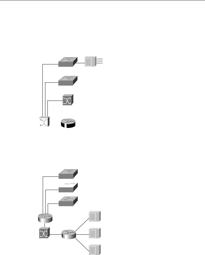
Phase 2 is the addition of high-speed backbone technology and routing between switches. LAN switches perform switch processing and provide dedicated bandwidth to the desktop and to shared-media hubs. Backbone routers are attached to either Fast Ethernet or ATM switches. The increase in backbone bandwidth matches the increase bandwidth in the wiring closet. Figure 2-25 shows an example of how you can add high-speed backbone technology and routing between existing switches in your network.
Figure 2-25 Adding high-speed backbone technology and routing between switches.
LAN switch
ATM campus switch
|
|
|
|
|
|
|
|
|
|
|
|
|
|
|
High-speed |
Router |
|||
core switch |
|
|||
In Phase 3, routers are distributed between the LAN switches in the wiring closet and the high-speed core switch. The network backbone is now strictly a high-speed transport mechanism with all other devices, such as the distributed routers, at the periphery. Figure 2-26 illustrates such a network.
Figure 2-26 Distributing routers between high-speed core and LAN switches.
 LAN switch
High-speed
switch
2-40 Cisco CCIE Fundamentals: Network Design

Summary
Phase 4 is the final phase—the end point. It involves end-to-end switching with integral VLANs and multilayer switching capability. By this point, Layer 2 and Layer 3 integrated switching is distributed across the network and is connected to the high-speed core. Figure 2-27 shows an example of this final phase.
Figure 2-27 End-to-end switching with VLAN and multilayer switching capability.
 Si
Si 
 Si
Si 
LAN switch
|
|
|
|
|
|
|
|
|
|
|
|
|
|
|
High-speed |
Router |
|||
core switch |
|
|||
Summary
Now that the basic internetworking devices and general design principles have been examined, the remaining chapters in this part focus on the different technologies available when designing an internetwork.
Internetworking Design Basics 2-41

Summary
2-42 Cisco CCIE Fundamentals: Network Design

C H A P T E R 3
Designing Large-Scale
IP Internetworks
This chapter focuses on the following design implications of the Enhanced Interior Gateway Routing Protocol (IGRP), Open Shortest Path First (OSPF) protocols, and the Border Gateway Protocol (BGP):
•
•
•
•
•
•
Network Topology
Addressing and Route Summarization
Route Selection
Convergence
Network Scalability
Security
Enhanced IGRP, OSPF, and BGP are routing protocols for the Internet Protocol (IP). An introductory discussion outlines general routing protocol issues; subsequent discussions focus on design guidelines for the specific IP protocols.
Implementing Routing Protocols
The following discussion provides an overview of the key decisions you must make when selecting and deploying routing protocols. This discussion lays the foundation for subsequent discussions regarding specific routing protocols.
Network Topology
The physical topology of an internetwork is described by the complete set of routers and the networks that connect them. Networks also have a logical topology. Different routing protocols establish the logical topology in different ways.
Some routing protocols do not use a logical hierarchy. Such protocols use addressing to segregate specific areas or domains within a given internetworking environment and to establish a logical topology. For such nonhierarchical, or flat , protocols, no manual topology creation is required.
Other protocols require the creation of an explicit hierarchical topology through establishment of a backbone and logical areas. The OSPF and Intermediate System-to-Intermediate System (IS-IS) protocols are examples of routing protocols that use a hierarchical structure. A general hierarchical network scheme is illustrated in Figure 3-1. The explicit topology in a hierarchical scheme takes precedence over the topology created through addressing.
Designing Large-Scale IP Internetworks 3-1

Implementing Routing Protocols
Figure 3-1 Hierarchical network.
Backbone
 Router

 Router


 Router


Area 1 |
Area 2 |
Area 3 |
If a hierarchical routing protocol is used, the addressing topology should be assigned to reflect the hierarchy. If a flat routing protocol is used, the addressing implicitly creates the topology. There are two recommended ways to assign addresses in a hierarchical network. The simplest way is to give each area (including the backbone) a unique network address. An alternative is to assign address ranges to each area.
Areas are logical collections of contiguous networks and hosts. Areas also include all the routers having interfaces on any one of the included networks. Each area runs a separate copy of the basic routing algorithm. Therefore, each area has its own topological database.
Addressing and Route Summarization
Route summarization procedures condense routing information. Without summarization, each router in a network must retain a route to every subnet in the network. With summarization, routers can reduce some sets of routes to a single advertisement, reducing both the load on the router and the perceived complexity of the network. The importance of route summarization increases with network size.
Figure 3-2 illustrates an example of route summarization. In this environment, Router R2 maintains one route for all destination networks beginning with B, and Router R4 maintains one route for all destination networks beginning with A. This is the essence of route summarization. Router R1 tracks all routes because it exists on the boundary between A and B.
3-2 Internetwork Design Guide