

Cisco. Fundamentals Network Design - Cisco Press
.pdfEvaluating Backbone Services
feature that allows you to avoid configuration errors by requiring the same key to be entered at each tunnel endpoint before the tunneled data is processed. IP tunneling also allows network designers to implement policies, such as which types of traffic can use which routes or assignment of priority or security levels to particular traffic. Capabilities like these are lacking in many native LAN protocols.
IP tunneling provides communication between subnetworks that have invalid or discontiguous network addresses. With tunneling, virtual network addresses are assigned to subnetworks, making discontiguous subnetworks reachable. Figure 2-11 illustrates that with GRE tunneling, it is possible for the two subnetworks of network 131.108.0.0 to talk to each other even though they are separated by another network.
Figure 2-11 Connecting discontiguous networks with tunnels.
131.108.20.0
255.255.255.0
Tunnel |
|
131.108.10.0 |
Router |
Router |
255.255.255.0 |
Network 192.1.1.0
Because encapsulation requires handling of the packets, it is generally faster to route protocols natively than to use tunnels. Tunneled traffic is switched at approximately half the typical process switching rates. This means approximately 1,000 packets per second (pps) aggregate for each router. Tunneling is CPU intensive, and as such, should be turned on cautiously. Routing updates, SAP updates, and other administrative traffic may be sent over each tunnel interface. It is easy to saturate a physical link with routing information if several tunnels are configured over it. Performance depends on the passenger protocol, broadcasts, routing updates, and bandwidth of the physical interfaces. It is also difficult to debug the physical link if problems occur. This problem can be mitigated in several ways. In IPX environments, route filters and SAP filters cut down on the size of the updates that travel over tunnels. In AppleTalk networks, keeping zones small and using route filters can limit excess bandwidth requirements.
Tunneling can disguise the nature of a link, making it look slower, faster, or more or less costly than it may actually be in reality. This can cause unexpected or undesirable route selection. Routing protocols that make decisions based only on hop count will usually prefer a tunnel to a real interface. This may not always be the best routing decision because an IP cloud can comprise several different media with very disparate qualities; for example, traffic may be forwarded across both 100-Mbps Ethernet lines and 9.6-Kbps serial lines. When using tunneling, pay attention to the media over which virtual tunnel traffic passes and the metrics used by each protocol.
If a network has sites that use protocol-based packet filters as part of a firewall security scheme, be aware that because tunnels encapsulate unchecked passenger protocols, you must establish filtering on the firewall router so that only authorized tunnels are allowed to pass. If tunnels are accepted from unsecured networks, it is a good idea to establish filtering at the tunnel destination or to place the tunnel destination outside the secure area of your network so that the current firewall scheme will remain secure.
Internetworking Design Basics 2-15

Identifying and Selecting Internetworking Capabilities
When tunneling IP over IP, you must be careful to avoid inadvertently configuring a recursive routing loop. A routing loop occurs when the passenger protocol and the transport protocol are identical. The routing loop occurs because the best path to the tunnel destination is via the tunnel interface. A routing loop can occur when tunneling IP over IP, as follows:
1The packet is placed in the output queue of the tunnel interface.
2The tunnel interface includes a GRE header and enqueues the packet to the transport protocol (IP) for the destination address of the tunnel interface.
3IP looks up the route to the tunnel destination address and learns that the path is the tunnel interface.
4Once again, the packet is placed in the output queue of the tunnel interface, as described in Step 1, hence, the routing loop.
When a router detects a recursive routing loop, it shuts down the tunnel interface for 1 to 2 minutes and issues a warning message before it goes into the recursive loop. Another indication that a recursive route loop has been detected is if the tunnel interface is up and the line protocol is down.
To avoid recursive loops, keep passenger and transport routing information in separate locations by implementing the following procedures:
•Use separate routing protocol identifiers (for example, igrp 1 and igrp 2).
•Use different routing protocols.
•Assign the tunnel interface a very low bandwidth so that routing protocols, such as IGRP, will recognize a very high metric for the tunnel interface and will, therefore, choose the correct next hop (that is, choose the best physical interface instead of the tunnel).
•Keep the two IP address ranges distinct; that is, use a major address for your tunnel network that is different from your actual IP network. Keeping the address ranges distinct also aids in debugging because it is easy to identify an address as the tunnel network instead of the physical network and vice versa.
Evaluating Distribution Services
This section addresses internetworking features that support distribution services. The following topics are discussed:
•
•
•
•
•
•
Backbone Bandwidth Management
Area and Service Filtering
Policy-Based Distribution
Gateway Service
Interprotocol Route Redistribution
Media Translation
Backbone Bandwidth Management
To optimize backbone network operations, routers offer several performance tuning features. Examples include priority queuing, routing protocol metrics, and local session termination.
2-16 Cisco CCIE Fundamentals: Network Design
Evaluating Distribution Services
You can adjust the output queue length on priority queues. If a priority queue overflows, excess packets are discarded and quench messages that halt packet flow are sent, if appropriate, for that protocol. You can also adjust routing metrics to increase control over the paths that the traffic takes through the internetwork.
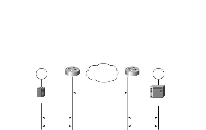
Local session termination allows routers to act as proxies for remote systems that represent session endpoints. (A proxy is a device that acts on behalf of another device.) Figure 2-12 illustrates an example of local session termination in an IBM environment.
Figure 2-12 Local session termination over multiprotocol backbone.
Token |
Router |
Multiprotocol |
Router |
Token |
|
Ring |
backbone |
Ring |
|||
|
|
||||
3745 |
|
TCP/IP session |
|
|
|
|
• Reliable transport |
|
3x74 controller |
||
|
|
|
•TCP flow control
•Error recovery
Acknowledgments |
|
Acknowledgments |
LLC2 session |
|
LLC2 session |
T1 timer |
|
T1 timer |
In Figure 2-12, the routers locally terminate Logical Link Control type 2 (LLC2) data-link control sessions. Instead of end-to-end sessions, during which all session control information is passed over the multiprotocol backbone, the routers take responsibility for acknowledging packets that come from hosts on directly attached LANs. Local acknowledgment saves WAN bandwidth (and, therefore, WAN utilization costs), solves session timeout problems, and provides faster response to users.
Area and Service Filtering
Traffic filters based on area or service type are the primary distribution service tools used to provide policy-based access control into backbone services. Both area and service filtering are implemented using access lists. An access list is a sequence of statements, each of which either permits or denies certain conditions or addresses. Access lists can be used to permit or deny messages from particular network nodes and messages sent using particular protocols and services.
Area or network access filters are used to enforce the selective transmission of traffic based on network address. You can apply these on incoming or outgoing ports. Service filters use access lists applied to protocols (such as IP’s UDP), applications such as the Simple Mail Transfer Protocol (SMTP), and specific protocols.
Suppose you have a network connected to the Internet, and you want any host on an Ethernet to be able to form TCP connections to any host on the Internet. However, you do not want Internet hosts to be able to form TCP connections to hosts on the Ethernet except to the SMTP port of a dedicated mail host.
SMTP uses TCP port 25 on one end of the connection and a random port number on the other end. The same two port numbers are used throughout the life of the connection. Mail packets coming in from the Internet will have a destination port of 25. Outbound packets will have the port numbers
Internetworking Design Basics 2-17

Identifying and Selecting Internetworking Capabilities
reversed. The fact that the secure system behind the router always accepts mail connections on port 25 is what makes it possible to separately control incoming and outgoing services. The access list can be configured on either the outbound or inbound interface.
In the following example, the Ethernet network is a Class B network with the address 128.88.0.0, and the mail host’s address is 128.88.1.2. The keyword established is used only for the TCP protocol to indicate an established connection. A match occurs if the TCP datagram has the ACK or RST bits set, which indicate that the packet belongs to an existing connection.
access-list 102 permit tcp 0.0.0.0 255.255.255.255 128.88.0.0 0.0.255.255 established access-list 102 permit tcp 0.0.0.0 255.255.255.255 128.88.1.2 0.0.0.0 eq 25
interface ethernet 0 ip access-group 102
Policy-Based Distribution
Policy-based distribution is based on the premise that different departments within a common organization might have different policies regarding traffic dispersion through the organization-wide internetwork. Policy-based distribution aims to meet the differing requirements without compromising performance and information integrity.
A policy within this internetworking context is a rule or set of rules that governs end-to-end distribution of traffic to (and subsequently through) a backbone network. One department might send traffic representing three different protocols to the backbone, but might want to expedite one particular protocol’s transit through the backbone because it carries mission-critical application information. To minimize already excessive internal traffic, another department might want to exclude all backbone traffic except electronic mail and one key custom application from entering its network segment.
These examples reflect policies specific to a single department. However, policies can reflect overall organizational goals. For example, an organization might want to regulate backbone traffic to a maximum of 10 percent average bandwidth during the work day and 1-minute peaks of 30 percent utilization. Another corporate policy might be to ensure that communication between two remote departments can freely occur, despite differences in technology.
Different policies frequently require different workgroup and department technologies. Therefore, support for policy-based distribution implies support for the wide range of technologies currently used to implement these policies. This in turn allows you to implement solutions that support a wide range of policies, which helps to increase organizational flexibility and application availability.
In addition to support for internetworking technologies, there must be a means both to keep separate and integrate these technologies, as appropriate. The different technologies should be able to coexist or combine intelligently, as the situation warrants.
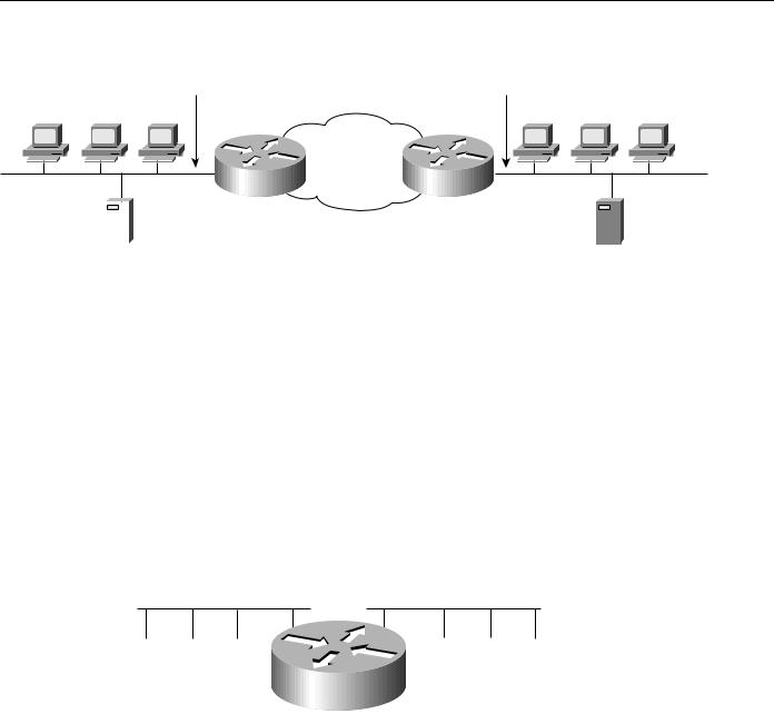
Consider the situation depicted in Figure 2-13. Assume that a corporate policy limits unnecessary backbone traffic. One way to do this is to restrict the transmission of Service Advertisement Protocol (SAP) messages. SAP messages allow NetWare servers to advertise services to clients. The organization might have another policy stating that all NetWare services should be provided locally. If this is the case, there should be no reason for services to be advertised remotely. SAP filters prevent SAP traffic from leaving a router interface, thereby fulfilling this policy.
2-18 Cisco CCIE Fundamentals: Network Design
Evaluating Distribution Services
Figure 2-13 Policy-based distributation: SAP filtering.
|
|
SAP filter |
SAP filter |
|
|
Client |
Client |
Client |
Client |
Client |
Client |
|
|
|
Backbone |
|
|
|
|
Router |
network |
|
|
|
|
Router |
|
|
|
|
|
|
|
|
|
|
|
|
|
|
|
|
|
|
|
|
NetWare server |
NetWare server |
||||
Gateway Service
Protocol gateway capabilities are part of each router’s standard software. For example, DECnet is currently in Phase V. DECnet Phase V addresses are different than DECnet Phase IV addresses. For those networks that require both type of hosts to coexist, two-way Phase IV/Phase V translation conforms to Digital-specified guidelines. The routers interoperate with Digital routers, and Digital hosts do not differentiate between the different devices.
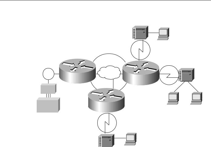
The connection of multiple independent DECnet networks can lead to addressing problems. Nothing precludes two independent DECnet administrators from assigning node address 10 to one of the nodes in their respective networks. When the two networks are connected at some later time, conflicts result. DECnet address translation gateways (ATGs) address this problem. The ATG solution provides router-based translation between addresses in two different DECnet networks connected by a router. Figure 2-14 illustrates an example of this operation.
Figure 2-14 Sample DECnet ATG implementation.
|
Network 0 |
Network 1 |
|
||
|
|
19.4 |
50.5 |
|
|
19.1 |
19.2 |
19.3 |
50.1 |
60.1 |
19.1 |
A:: |
B:: |
C:: |
D:: |
E:: |
F:: |
|
|
E0 |
E1 |
|
|
|
|
|
Router A |
|
|
19.5 50.1
50.1
19.6 19.1
19.1
19.1 47.1
47.1
19.3  47.2 DECnet translation table
In Network 0, the router is configured at address 19.4 and is a Level 1 router. In Network 1, the router is configured at address 50.5 and is an area router. At this point, no routing information is exchanged between the two networks. The router maintains a separate routing table for each network. By establishing a translation map, packets in Network 0 sent to address 19.5 will be routed to Network 1, and the destination address will be translated to 50.1. Similarly, packets sent to address 19.6 in Network 0 will be routed to Network 1 as 19.1; packets sent to address 47.1 in Network 1 will be routed to Network 0 as 19.1; and packets sent to 47.2 in Network 1 will be sent to Network 0 as 19.3.
Internetworking Design Basics 2-19

Identifying and Selecting Internetworking Capabilities
AppleTalk is another protocol with multiple revisions, each with somewhat different addressing characteristics. AppleTalk Phase 1 addresses are simple local forms; AppleTalk Phase 2 uses extended (multinetwork) addressing. Normally, information sent from a Phase 2 node cannot be understood by a Phase 1 node if Phase 2 extended addressing is used. Routers support routing between Phase 1 and Phase 2 nodes on the same cable by using transitional routing.
You can accomplish transitional routing by attaching two router ports to the same physical cable. Configure one port to support nonextended AppleTalk and the other to support extended AppleTalk. Both ports must have unique network numbers. Packets are translated and sent out the other port as necessary.
Interprotocol Route Redistribution
The preceding section, “Gateway Service,” discussed how routed protocol gateways (such as one that translates between AppleTalk Phase 1 and Phase 2) allow two end nodes with different implementations to communicate. Routers can also act as gateways for routing protocols. Information derived from one routing protocol, such as the IGRP, can be passed to, and used by, another routing protocol, such as RIP. This is useful when running multiple routing protocols in the same internetwork.
Routing information can be exchanged between any supported IP routing protocols. These include RIP, IGRP, OSPF, HELLO, EGP, and BGP. Similarly, route redistribution is supported by ISO CLNS for route redistribution between ISO IGRP and IS-IS. Static route information can also be redistributed. Defaults can be assigned so that one routing protocol can use the same metric for all redistributed routes, thereby simplifying the routing redistribution mechanism.
Media Translation
Media translation techniques translate frames from one network system into frames of another. Such translations are rarely 100 percent effective because one system might have attributes with no corollary to the other. For example, Token Ring networks support a built-in priority and reservation system, whereas Ethernet networks do not. Translations between Token Ring and Ethernet networks must somehow account for this discrepancy. It is possible for two vendors to make different decisions about how this discrepancy will be handled, which can prevent multivendor interoperation.
For those situations in which communication between end stations on different media is required, routers can translate between Ethernet and Token Ring frames. For direct bridging between Ethernet and Token Ring environments, use either source-route translational bridging or source-route transparent bridging (SRT). Source-route translational bridging translates between Token Ring and Ethernet frame formats; SRT allows routers to use both SRB and the transparent bridging algorithm used in standard Ethernet bridging.
When bridging from the SRB domain to the transparent bridging domain, the SRB fields of the frames are removed. RIFs are cached for use by subsequent return traffic. When bridging in the opposite direction, the router checks the packet to determine whether it has a multicast or broadcast destination or a unicast destination. If it has a multicast or broadcast destination, the packet is sent as a spanning-tree explorer. If it has a unicast destination, the router looks up the path to the destination in the RIF cache. If a path is found, it will be used; otherwise, the router will send the packet as a spanning-tree explorer. A simple example of this topology is shown in Figure 2-15.
2-20 Cisco CCIE Fundamentals: Network Design

Evaluating Distribution Services
Figure 2-15 |
Source-route translational bridging topology. |
|||||
|
|
|
|
|
|
Transparent |
|
|
|
|
|
|
bridging ring |
Source-route |
|
|
|
|
Transparent |
|
bridged domain |
|
|
|
|
||
|
|
|
|
bridging domain |
||
|
|
|
|
|
|
|
Token |
|
|
|
|
Router |
|
Ring |
|
|
|
|
||
|
|
|
|
|
||
|
|
|
|
|
|
|
|
|
|
|
Source-route |
||
|
|
translational bridging |
||||
Frames lose their RIFs in this direction
Frames gain RIFs in this direction
Routers support SRT through implementation of both transparent bridging and SRB algorithms on each SRT interface. If an interface notes the presence of a RIF field, it uses the SRB algorithm; if not, it uses the transparent bridging algorithm.
Translation between serial links running the SDLC protocol and Token Rings running LLC2 is also available. This is referred to as SDLLC frame translation. SDLLC frame translation allows connections between serial lines and Token Rings. This is useful for consolidating traditionally disparate SNA/SDLC networks into a LAN-based, multiprotocol, multimedia backbone network. Using SDLLC, routers terminate SDLC sessions, translate SDLC frames to LLC2 frames, and then forward the LLC2 frames using RSRB over a point-to-point or IP network. Because a router-based IP network can use arbitrary media, such as FDDI, Frame Relay, X.25, or leased lines, routers support SDLLC over all such media through IP encapsulation.
A complex SDLLC configuration is shown in Figure 2-16.
Internetworking Design Basics 2-21
Identifying and Selecting Internetworking Capabilities
Figure 2-16 |
Complex SDLLC configuration. |
|
|
|
|
|
||
|
|
|
|
|
3x74 |
3270 |
|
|
|
|
|
|
|
|
|
||
|
|
|
|
|
C1 |
|
|
|
|
|
RSRB Virtual Ring 100 |
|
|
SDLLC |
|
|
|
|
|
|
|
Ring 7 |
|
|
||
|
|
|
|
|
|
|
|
|
|
|
|
|
|
S0 |
|
SDLLC |
|
|
|
|
|
|
|
Ring 8 |
3x74 |
|
|
|
|
|
|
|
|
|
|
Token |
E0 |
WAN |
|
|
|
S1 |
C2 |
|
Ring 10 |
|
|
|
Router B |
|
|||
|
T0 Router A |
|
|
E0 |
|
|
|
|
|
|
|
|
SDLLC |
|
|
|
|
|
|
|
|
|
|
|
|
|
37x5 |
|
|
E0 |
|
|
|
|
|
|
|
|
|
|
|
|
|
|
Host |
|
Router C |
S0 |
|
|
|
3270 |
3270 |
|
|
SDLLC |
|
|
|
|||
|
|
|
|
|
|
|
||
SDLLC
Ring 9
C3

 3270 3x74
Evaluating Local-Access Services
The following discussion addresses internetworking features that support local-access services. Local-access service topics outlined here include the following:
•
•
•
•
•
•
Value-Added Network Addressing
Network Segmentation
Broadcast and Multicast Capabilities
Naming, Proxy, and Local Cache Capabilities
Media Access Security
Router Discovery
Value-Added Network Addressing
Address schemes for LAN-based networks, such as NetWare and others, do not always adapt perfectly to use over multisegment LANs or WANs. One tool routers implement to ensure operation of such protocols is protocol-specific helper addressing. Helper addressing is a mechanism to assist the movement of specific traffic through a network when that traffic might not otherwise transit the network.
2-22 Cisco CCIE Fundamentals: Network Design
Evaluating Local-Access Services
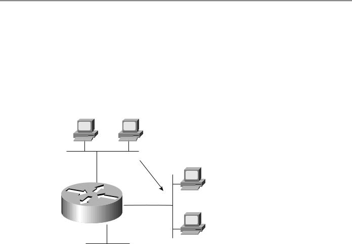
The use of helper addressing is best illustrated with an example. Consider the use of helper addresses in Novell IPX internetworks. Novell clients send broadcast messages when looking for a server. If the server is not local, broadcast traffic must be sent through routers. Helper addresses and access lists can be used together to allow broadcasts from certain nodes on one network to be directed specifically to certain servers on another network. Multiple helper addresses on each interface are supported, so broadcast packets can be forwarded to multiple hosts. Figure 2-17 illustrates the use of NetWare-based helper addressing.
Figure 2-17 Sample network map illustrating helper address broadcast control.
NetWare |
NetWare |
|
client B |
client A |
|
|
AA |
|
|
Allows type 10 |
|
|
broadcasts only |
|
|
NetWare |
|
|
server A |
|
|
00b4.23cd.110a |
|
|
E0 |
|
|
BB |
|
Router C1 |
E1 |
|
NetWare |
||
E2 |
||
server B |
||
|
||
|
0090.aa23.ef01 |
CC
NetWare clients on Network AA are allowed to broadcast to any server on Network BB. An applicable access list would specify that broadcasts of type 10 will be permitted from all nodes on Network AA. A configuration-specified helper address identifies the addresses on Network BB to which these broadcasts are directed. No other nodes on Network BB receive the broadcasts. No other broadcasts other than type 10 broadcasts are routed.
Any downstream networks beyond Network AA (for example, some Network AA1) are not allowed to broadcast to Network BB through Router C1, unless the routers partitioning Networks AA and AA1 are configured to forward broadcasts with a series of configuration entries. These entries must be applied to the input interfaces and be set to forward broadcasts between directly connected networks. In this way, traffic is passed along in a directed manner from network to network.
Network Segmentation
The splitting of networks into more manageable pieces is an essential role played by local-access routers. In particular, local-access routers implement local policies and limit unnecessary traffic. Examples of capabilities that allow network designers to use local-access routers to segment networks include IP subnets, DECnet area addressing, and AppleTalk zones.
You can use local-access routers to implement local policies by placing the routers in strategic locations and by configuring specific segmenting policies. For example, you can set up a series of LAN segments with different subnet addresses; routers would be configured with suitable interface addresses and subnet masks. In general, traffic on a given segment is limited to local broadcasts,
Internetworking Design Basics 2-23

Identifying and Selecting Internetworking Capabilities
traffic intended for a specific end station on that segment, or traffic intended for another specific router. By distributing hosts and clients carefully, you can use this simple method of dividing up a network to reduce overall network congestion.
Broadcast and Multicast Capabilities
Many protocols use broadcast and multicast capabilities. Broadcasts are messages that are sent out to all network destinations. Multicasts are messages sent to a specific subset of network destinations. Routers inherently reduce broadcast proliferation by default. However, routers can be configured to relay broadcast traffic if necessary. Under certain circumstances, passing along broadcast information is desirable and possibly necessary. The key is controlling broadcasts and multicasts using routers.
In the IP world, as with many other technologies, broadcast requests are very common. Unless broadcasts are controlled, network bandwidth can be seriously reduced. Routers offer various broadcast-limiting functions that reduce network traffic and minimize broadcast storms. For example, directed broadcasting allows for broadcasts to a specific network or a series of networks, rather than to the entire internetwork. When flooded broadcasts (broadcasts sent through the entire internetwork) are necessary, Cisco routers support a technique by which these broadcasts are sent over a spanning tree of the network. The spanning tree ensures complete coverage without excessive traffic because only one packet is sent over each network segment.
As discussed previously in the section “Value-Added Network Addressing,” broadcast assistance is accommodated with the helper address mechanisms. You can allow a router or series of routers to relay broadcasts that would otherwise be blocked by using helper addresses. For example, you can permit retransmission of SAP broadcasts using helper addresses, thereby notifying clients on different network segments of certain NetWare services available from specific remote servers.
The Cisco IP multicast feature allows IP traffic to be propagated from one source to any number of destinations. Rather than sending one packet to each destination, one packet is sent to a multicast group identified by a single IP destination group address. IP multicast provides excellent support for such applications as video and audio conferencing, resource discovery, and stock market traffic distribution.
For full support of IP multicast, IP hosts must run the Internet Group Management Protocol (IGMP). IGMP is used by IP hosts to report their multicast group memberships to an immediately neighboring multicast router. The membership of a multicast group is dynamic. Multicast routers send IGMP query messages on their attached local networks. Host members of a multicast group respond to a query by sending IGMP reports for multicast groups to which they belong. Reports sent by the first host in a multicast group suppress the sending of identical reports from other hosts of the same group.
The multicast router attached to the local network takes responsibility for forwarding multicast datagrams from one multicast group to all other networks that have members in the group. Routers build multicast group distribution trees (routing tables) so that multicast packets have loop-free paths to all multicast group members so that multicast packets are not duplicated. If no reports are received from a multicast group after a set number of IGMP queries, the multicast routers assume the group has no local members and stop forwarding multicasts intended for that group.
Cisco routers also support Protocol Independent Multicast (PIM). For more information on this topic, see Chapter 13, “Designing Internetworks for Multimedia.”
Naming, Proxy, and Local Cache Capabilities
Three key router capabilities help reduce network traffic and promote efficient internetworking operation: name service support, proxy services, and local caching of network information.
2-24 Cisco CCIE Fundamentals: Network Design