


Routing Protocols 53
NOTE Cisco IOS provides a detailed version of the ping tool, which you can evoke by typing ping in the enabled mode. This command is known as the extended ping command.
Telnet
Telnet is an application layer protocol and part of the TCP/IP protocol suite. The TCP destination port number is 23 and commonly manages routers and switches, for example. Telnet is an insecure protocol, as data flows in plain text and the Telnet passwords can be sniffed. SSH is more secure for remote logins.
File Transfer Protocol and Trivial File Transfer Protocol
|
File Transfer Protocol (FTP) and Trivial File Transfer Protocol (TFTP) are application layer |
|
protocols (part of the TCP/IP protocol suite of applications). FTP is a connection-oriented |
|
protocol running over TCP. FTP uses two connections to maintain connectivity between two IP |
|
hosts; port 20 is used for server applications and port 21 for data transfer. |
|
TFTP runs over UDP port 69 and is a connectionless-based protocol. TFTP commonly uploads |
|
IOS and configurations to a TFTP server. TFTP is regarded as the simple version of FTP. TFTP |
|
does not require any username/password combination to transfer data, as opposed to FTP, where |
|
a username and password are required before data can be transferred. |
|
|
NOTE |
Domain Name Server (DNS) is another common application that uses both TCP and UDP port 53. |
|
|
|
Now that you fully appreciate the TCP/IP model, the next section covers routing protocols used |
|
to ensure TCP/IP data can be moved, or routed, from one location to another. |
Routing Protocols
This section covers four main routing protocols:
•
•
•
•
RIP
EIGRP
OSPF
BGP
Before discussing the characteristic of each protocol, this section covers how routers (Cisco routers, in particular) generally route IP packets.

54 Chapter 2: General Networking Topics
Routing is a process whereby a path to a destination host is selected by either a dynamic or static routing protocol. A routing protocol is an algorithm that routes data across the network. Each router makes routing decisions from host to destination based on specific metrics used by the operating routing protocol. For example, RIP uses hop count (commonly known as the network diameter) to decide what router interface the data is sent. A lower hop count is always preferred. OSPF, on the other hand, uses a cost metric; the lower the cost, the more preferred a path to the destination.
Routing IP across a network of Cisco routers requires IP address allocation to interfaces and then a static or dynamic routing protocol to advertise these networks to local or remote routers. After these networks are advertised, IP data can flow across the network. Routing occurs at Layer 3 (the network layer) of the OSI model.
By default, IP routing is enabled on Cisco routers. The command used to start or disable IP routing is [no] ip routing. By default, IP routing is enabled so you will not see this command by viewing the configuration. Consider a one-router network with two directly connected Ethernet interfaces as an introductory example. Figure 2-13 displays a two-port Ethernet router configured with two subnets.
Figure 2-13 Connected Routes
Directly Connected Networks
172.108.1.1/24 |
R1 |
172.108.2.1/24 |
|
|
|
|
|
|||||||
|
|
|
|
|
E0 |
|
|
E1 |
|
|
|
|
|
|
|
|
|
|
|
|
|
|
|
|
|
|
|
||
|
|
|
|
|
|
|
|
|
|
|
|
|
|
|
|
|
|
|
|
|
|
|
|
|
|
|
|
|
|
|
|
|
|
|
|
|
|
|
|
|
|
|
|
|
|
|
|
|
|
|
|
|
|
|
|
|
|||
|
PC 1 |
|
|
|
|
|
PC 2 |
|||||||
|
|
|
|
|
|
|
|
|
|
|
|
|
|
|
R1# show ip route
Codes C- connected, S- static, I- IGRP, R- RIP, M- mobile, B- BGP D- EIGRP, EXEIGRP external, Q- QSPF, 1AOSPF inter area
N1OSPF NSSA external type 1, N2OSPF NSSA external type 2 E1OSPF external type 1, E2OSPF external type 2, E- EGP
i- IS-IS, L1- IS-IS level-1, L2- IS-IS level-2.*-candidate default U- per-user static route, o- ODR
-
Gateway of last resort is not set
-
172.108.0.0/24 is subnetted, 2 subnets
C172.108.1.0 is directly connected, Ethernet0
C172.108.2.0 is directly connected, Ethernet1
R1#
PC1 can communicate with PC2 as shown in Figure 2-13, because Cisco routers will route to directly connected interfaces.

Routing Protocols 55
The IOS command show ip route is used to view the IP routing table, and a number of symbols define how remote or local networks have been discovered. Table 2-7 defines the various symbols and their meanings. The Cisco Documentation CD defines the routing fields or codes as follows.
Table 2-7 show ip route Defined*
Field |
Description |
|
|
O |
Indicates protocol that derived the route. |
|
Possible values include the following: |
|
I—IGRP derived |
|
R—RIP derived |
|
O—OSPF derived |
|
C—Connected |
|
S—Static |
|
E—EGP derived |
|
B—BGP derived |
|
D—EIGRP |
|
EX—EIGRP external |
|
I—IS-IS derived |
|
Ia—IS-IS |
|
M—Mobile |
|
P—Periodic downloaded static route |
|
U—Per-user static route |
|
O—On-demand routing |
|
|
E2 |
Type of route. Possible values include the |
|
following: |
|
*—Indicates the last path used when a |
|
packet was forwarded. It pertains only to the |
|
nonfast-switched packets. However, it does |
|
not indicate what path will be used next |
|
when forwarding a nonfast-switched packet, |
|
except when the paths are equal cost. |
|
IA—OSPF interarea route |
|
E1—OSPF external type 1 route |
|
E2—OSPF external type 2 route |
|
L1—IS-IS Level 1 route |
|
L2—IS-IS Level 2 route |
|
N1—OSPF NSSA external type 1 route |
|
N2—OSPF NSSA external type 2 route |
|
|
continues

56 Chapter 2: General Networking Topics
Table 2-7 |
show ip route Defined* (Continued) |
|
|
|
|
|
|
|
Field |
Description |
|
|
|
|
|
|
172.108.0.0/24 is subnetted, 2 subnets |
Indicates the address of the remote network. |
|
|
C |
172.108.1.0 is directly connected, Ethernet0 |
|
|
C |
172.108.2.0 is directly connected, Ethernet1 |
|
|
R1# |
|
|
|
|
|
|
|
[160/5] |
The first number in the brackets is the |
|
|
|
|
information source’s administrative |
|
|
|
distance; the second number is the metric |
|
|
|
for the route. |
|
|
|
|
|
via |
|
Specifies the address of the next router to |
|
|
|
the remote network. |
|
|
|
|
|
0:01:00 |
Specifies the last time the route was updated |
|
|
|
|
in hours:minutes:seconds. |
|
|
|
|
|
Ethernet0 |
Specifies the interface through which the |
|
|
|
|
specified network can be reached. |
|
|
|
|
*Part of this table taken from http://www.cisco.com/univercd/cc/td/doc/product/software/ios122/122cgcr/fiprrp_r/ind_r/1rfindp2.htm#102251, all rights are reserved to Cisco.
By default, Cisco IOS assigns each routing protocol an administrative distance (AD) that indicates the trustworthiness of a routing entry if there is more than one path to a remote network running two or more routing algorithms. You can configure the AD value from the default with the distance administrative-distance IOS command if you want to manually choose RIP over OSPF, for example. The value for administrative-distance can be 1 to 255.
Table 2-8 displays the administrative distances enabled by default on Cisco routers.
Table 2-8 |
Default Administrative Distances |
|
|
|
|
|
Route Source |
Default Distance |
|
|
|
|
Connected interface (or static route via a |
0 |
|
connected interface) |
|
|
|
|
|
Static route |
1 |
|
|
|
|
Enhanced IGRP summary route |
5 |
|
|
|
|
External BGP |
20 |
|
|
|
|
Internal enhanced IGRP |
90 |
|
|
|
|
IGRP |
100 |
|
|
|

Routing Protocols 57
Table 2-8 |
Default Administrative Distances (Continued) |
|
|
|
|
|
|
|
Route Source |
|
Default Distance |
|
|
|
|
|
OSPF |
|
110 |
|
|
|
|
|
IS-IS |
|
115 |
|
|
|
|
|
RIP |
|
120 |
|
|
|
|
|
EGP |
|
140 |
|
|
|
|
|
EIGRP external route |
|
170 |
|
|
|
|
|
Internal BGP |
|
200 |
|
|
|
|
|
Unknown |
|
255 |
|
|
|
|
|
For example, Table 2-8 demonstrates that an EIGRP (AD 90) route is preferred over a network |
||
|
entry discovered by RIP (AD 120) because the AD is lower, or more trustworthy. |
||
|
|
|
|
NOTE |
The IP address source and destination in an IP datagram does not alter, but the Layer 2 MAC |
||
|
source and destination do, for example, when PC1 sends a packet to PC2 in Figure 2-13. The |
||
|
TCP/IP software on PC1 identifies that the remote destination (172.108.2.0/24) is not locally |
||
|
connected and sends the Layer 3 frame to the local gateway address, 171.108.1.1/24. For the |
||
|
Layer 2 frame to transverse the local Ethernet, the destination Layer 2 Mac address must be that |
||
|
of the local router or gateway. PC2 resides on a different subnet, so the destination MAC |
||
|
address will be that of Router R1 (E0 burnt in address), or the default gateway address of |
||
|
172.108.1.1. Router R1 will then strip the Layer 2 header and install its own Layer 2 header |
||
|
when the packet enters the network where PC2 resides. The Layer 2 header contains the source |
||
|
address (Layer 2) of R1 E1 and destination address of PC2’s MAC address. The Layer 3 IP |
||
source and destination addresses do not change during the routing of the IP packet. The exception to changes in Layer 3 addressing is when Network Address Translation (NAT) is used.
Routing Information Protocol
Routing Information Protocol (RIP) is one the oldest routing protocols in use today.
RIP is a distance vector protocol. Table 2-9 defines the characteristics of a distance vector protocol.
58 Chapter 2: General Networking Topics
Table 2-9 |
Distance Vector Protocol Characteristics |
|
|
|
|
|
Characteristic |
Description |
|
|
|
|
Periodic updates |
Periodic updates are sent at a set interval; for IP RIP, this interval is 30 seconds. |
|
|
|
|
Broadcast updates |
Updates are sent to the broadcast address 255.255.255.255. Only devices |
|
|
running routing algorithms will listen to these updates. |
|
|
|
|
Full table updates |
When an update is sent, the entire routing table is sent. |
|
|
|
|
Triggered updates |
Also known as Flash updates, these are sent when a change occurs outside the |
|
|
update interval. |
|
|
|
|
Split horizon |
This method stops routing loop. Updates are not sent out an outgoing interface |
|
|
from which the source network was received. This saves bandwidth, as well. |
|
|
|
|
Count to infinity |
Maximum hop count. For RIP, it’s 15, and for IGRP, it’s 255. |
|
|
|
|
Algorithm |
Example: Bellman-Ford for RIP. |
|
|
|
|
Examples |
RIP and IGRP. |
|
|
|
RIP comes in two versions: RIPv1 (does not support VLSM) and RIPv2. Both versions of RIP automatically summarize at the network boundary (you can configure classful routing protocol, RIPv2, to support VLSM).
The following list summarizes RIPv1 characteristics:
•
•
•
•
•
•
•
•
•
Distance vector protocol
Runs over UDP port 520
Metric is hop count (maximum is 15; 16 is unreachable)
Periodic updates every 30 seconds
Up to 25 networks per RIP update
Implements Split horizon
Implements triggered updates
No support for VLSM or authentication
Administrative Distance is 120
NOTE |
Split horizon is a routing technique in which information about routes is prevented from exiting |
|
the router interface through which that information was received. Split horizon updates are |
|
useful in preventing routing loops. To enable split horizon, the IOS command is ip split- |
|
horizon. Split horizon on frame relay subinterfaces is enabled by default. Always use the |
|
IOS command show ip interface to determine if split horizon is enabled or displayed. |

Routing Protocols 59
A triggered update is a method by which a routing protocol sends an instant message as soon as a network failure is detected. If a triggered update were not used, the only way the update would be sent would be via the normal update every 30 seconds, causing a delay in network convergence times. Split horizon is a favorite topic in CCIE lab exams.
Poison Reverse updates explicitly indicate that a network is unreachable rather than implying a remote network is unreachable by not sending that network in an update. Poison Reverse updates are intended to defeat routing loops in large IP networks.
Split horizon, Poison Reverse, and triggered updates are methods used by distance vector protocols to avoid routing loops.
RIPv2 was developed to enable RIP to support VLSM, so it is a classless routing protocol that also supports authentication. RIPv2 uses the same hop count and metric.
The following list summarizes RIPv2 characteristics:
•Distance vector protocol
•Runs over UDP port 520
•Metric is hop count (maximum is 15; 16 is unreachable)
•Periodic updates every 30 seconds
•Up to 25 networks per RIP update
•Implements Split horizon
•Implements triggered updates
•Supports VLSM (subnet mask carried in updates)
•Supports authentication
•Administrative Distance is 120
•Updates sent to multicast address 224.0.0.9
•Can set up neighbors to reduce broadcast traffic (send unicast updates) To enable RIP on a Cisco router, the command required is router rip.
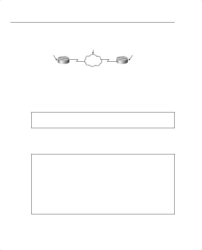
Consider a two-router topology running VLSM and RIP. Figure 2-14 displays two routers, named R1 and R2, with a /30-bit network used across the WAN. Loopbacks are used to populate the IP routing tables.
To start, enable RIP on both routers with the commands in Example 2-10. Version 2 must be enabled because you are implementing VLSM across the WAN links between R1 and R2.
60 Chapter 2: General Networking Topics
Figure 2-14 Practical Example of Routing RIP
131.108.3.0/30 Frame Relay
172.108.1.1/24 |
|
|
|
|
172.108.2.1/24 |
||
|
|
|
|
|
|
|
|
|
E0/0 |
S0/0 |
S0/0 |
|
E0/0 |
|
|
|
|
R1 |
.1 |
.2 |
R2 |
|
|
|
|
|
|
||||
|
|
|
|
|
|
||
|
R1's Loopbacks |
|
R2's Loopbacks |
|
|
||
|
Loopback0 131.108.4.1/24 |
Loopback0 131.108.7.1/24 |
|||||
|
Loopback1 131.108.5.1/24 |
Loopback1 131.108.8.1/24 |
|||||
|
Loopback2 131.108.6.1/24 |
Loopback2 131.108.9.1/24 |
|||||
Example 2-10 displays the RIP configuration on R1. The same configuration commands are applied to R2.
Example 2-10 IP RIP Configuration on R1
router rip version 2
network 131.108.0.0
View the RIP forward database with the command, show ip rip database. Example 2-11 displays the output when show ip rip database is executed on R1.
Example 2-11 show ip rip database Command on R1
R1#show ip rip database
131.108.0.0/16 auto-summary
131.108.1.0/24 directly connected, Ethernet0/0 131.108.2.0/24
[1] via 131.108.3.2, 00:00:12, Serial0/0 131.108.3.0/30 directly connected, Serial0/0 131.108.4.0/24 directly connected, Loopback0 131.108.5.0/24 directly connected, Loopback1 131.108.6.0/24 directly connected, Loopback2 131.108.7.0/24
[1] via 131.108.3.2, 00:00:12, Serial0/0 131.108.8.0/24
[1] via 131.108.3.2, 00:00:12, Serial0/0 131.108.9.0/24
[1] via 131.108.3.2, 00:00:12, Serial0/0

Routing Protocols 61
Example 2-11 displays the directly connected routers and the four dynamically discovered routers via Serial0/0 to R2. To confirm that the entries are reachable, display the IP routing table on R1 and perform a few ping requests across the Frame Relay cloud.
Example 2-12 displays the IP routing table and the successful ping requests to the four remote networks.
Example 2-12 show ip route and ping to R2
R1#show ip route
Codes: C - connected, R - RIP,
131.108.0.0/16 is variably subnetted, 9 subnets, 2 masks
R131.108.9.0/24 [120/1] via 131.108.3.2, 00:00:00, Serial0/0
R131.108.8.0/24 [120/1] via 131.108.3.2, 00:00:00, Serial0/0
R131.108.7.0/24 [120/1] via 131.108.3.2, 00:00:00, Serial0/0 C 131.108.6.0/24 is directly connected, Loopback2
C 131.108.5.0/24 is directly connected, Loopback1 C 131.108.4.0/24 is directly connected, Loopback0 C 131.108.3.0/30 is directly connected, Serial0/0
R131.108.2.0/24 [120/1] via 131.108.3.2, 00:00:01, Serial0/0 C 131.108.1.0/24 is directly connected, Ethernet0/0
R1#ping 131.108.2.1
Type escape sequence to abort.
Sending 5, 100-byte ICMP Echos to 131.108.2.1, timeout is 2 seconds:
!!!!!
Success rate is 100 percent (5/5), round-trip min/avg/max = 4/6/8 ms R1#ping 131.108.7.1
Type escape sequence to abort.
Sending 5, 100-byte ICMP Echos to 131.108.7.1, timeout is 2 seconds:
!!!!!
Success rate is 100 percent (5/5), round-trip min/avg/max = 4/6/8 ms R1#ping 131.108.8.1
Type escape sequence to abort.
Sending 5, 100-byte ICMP Echos to 131.108.8.1, timeout is 2 seconds:
!!!!!
Success rate is 100 percent (5/5), round-trip min/avg/max = 4/5/8 ms R1#ping 131.108.9.1
Type escape sequence to abort.
Sending 5, 100-byte ICMP Echos to 131.108.9.1, timeout is 2 seconds:
!!!!!
Success rate is 100 percent (5/5), round-trip min/avg/max = 4/5/8 ms R1#
Example 2-12 displays the four remote networks reachable by the Serial 0/0 and four successful ping requests (five replies to each remote network) to those interfaces on R2.
Stop R2 from sending R1 any updates via the Frame cloud to demonstrate the passive-interface command, passive-interface Serial0/0.

62 Chapter 2: General Networking Topics
Example 2-13 displays the passive interface configuration on R2 serial0/0.
Example 2-13 Passive Interface Configuration on R2
R2(config)#router rip
R2(config-router)#passive-interface serial 0/0
R1’s routing table now contains no remote entries from R2, which will still receive updates because the command affects only outbound updates. Example 2-14 confirms the missing routing RIP entries in R1’s IP routing table.
Example 2-14 show ip route on R1
R1#show ip route
Codes: C - connected,
131.108.0.0/16 is variably subnetted, 5 subnets, 2 masks
C131.108.6.0/24 is directly connected, Loopback2
C131.108.5.0/24 is directly connected, Loopback1
C131.108.4.0/24 is directly connected, Loopback0
C131.108.3.0/30 is directly connected, Serial0/0
C131.108.1.0/24 is directly connected, Ethernet0/0
EIGRP
EIGRP is a Cisco-developed routing protocol that uses the same metric defined by IGRP multiplied by 256. The routing metric in EIGRP is based on bandwidth, delay, load, and reliability. The CCIE Security written exam does not test the candidates’ understanding of EIGRP too greatly, so this section includes only the relevant topics for the exam.
EIGRP is a Cisco proprietary routing protocol that can be used to route a number of Layer 3 protocols, including IP, IPX, and AppleTalk. This section is concerned only with routing IP.
To ensure EIGRP is as efficient as possible, the following features were built into EIGRP:
•Rapid convergence—EIGRP uses the Diffusing Update Algorithm (DUAL) to achieve rapid convergence. A Cisco IOS router that runs EIGRP will ensure any redundant paths are stored and used in case of a network failure.
•Reduced bandwidth usage—By default, EIGRP uses up to 50 percent of available bandwidth, and this option can be changed with the IOS command ip bandwidth-percent eigrp as-number percent. By default, EIGRP uses up to 50 percent of the bandwidth defined by the interface bandwidth command. The interface command, ip eigrp- bandwidth-percent <0-100%>, can be used to change this value (a good method to use for the CCIE lab).
EIGRP is consider a hybrid routing protocol, meaning that EIGRP uses characteristics of both distance vector and link-state routing protocols to maintain routing tables.

Routing Protocols 63
EIGRP Terminology
EIGRP has a number of terms that must be understood by a candidate for the CCIE Security written exam. Table 2-10 defines some of the common terminology used in EIGRP.
Table 2-10 EIGRP Terms
Term |
Meaning |
|
|
Neighbor |
A router in the same autonomous system (AS) running EIGRP. |
|
|
Neighbor table |
EIGRP maintains a table with all adjacent routers. To view the |
|
EIGRP neighbors, use the IOS command show ip eigrp |
|
neighbors. |
|
|
Topology table |
EIGRP maintains a topology table for all remote destinations |
|
discovered by neighboring routers. To view the topology table, |
|
the IOS command is show ip eigrp topology. |
|
|
Hello |
A packet used to monitor and maintain EIGRP neighbor |
|
relationships; they are multicast. |
|
|
Query |
A query packet that is sent to neighboring routers when a network |
|
path is lost; can be multicast or unicast. |
|
|
Reply |
A reply packet to a query packet; they are unicast. |
|
|
ACK |
Acknowledgment of an update packet, typically a hello packet |
|
with no data; they are unicast. |
|
|
Holdtime |
How long a router waits for a hello packet before tearing down a |
|
neighbor adjacency. |
|
|
Smooth Route Trip Time (SRTT) |
Time taken to send a packet reliably to an acknowledgment. SRTT |
|
is the average delta between the time a packet is sent and the |
|
arrival of the neighbor’s acknowledgment. |
|
|
Retransmission Timeout (RTO) |
RTO is the time a router waits for the arrival of the neighbor’s |
|
acknowledgment. |
|
|
Feasible distance |
Lowest metric to remote network. |
|
|
Feasibility condition (FC) |
A condition under which the sum of a neighbor’s cost to a |
|
destination and the cost to this neighbor is less than current |
|
successor’s cost. |
|
|
Feasible successor |
A neighboring router with a lower AD. |
|
|
Successor |
A neighboring router that meets the feasibility condition. |
|
|
Stuck in Active (SIA) |
An EIGRP router waiting for all acknowledgments from |
|
neighboring routers for all the queries sent. |
|
|
Active |
When a router is querying neighboring routers about a network |
|
path. |
|
|
Passive |
Normal route operation to a remote destination. |
|
|
64 Chapter 2: General Networking Topics
EIGRP Configuration Example
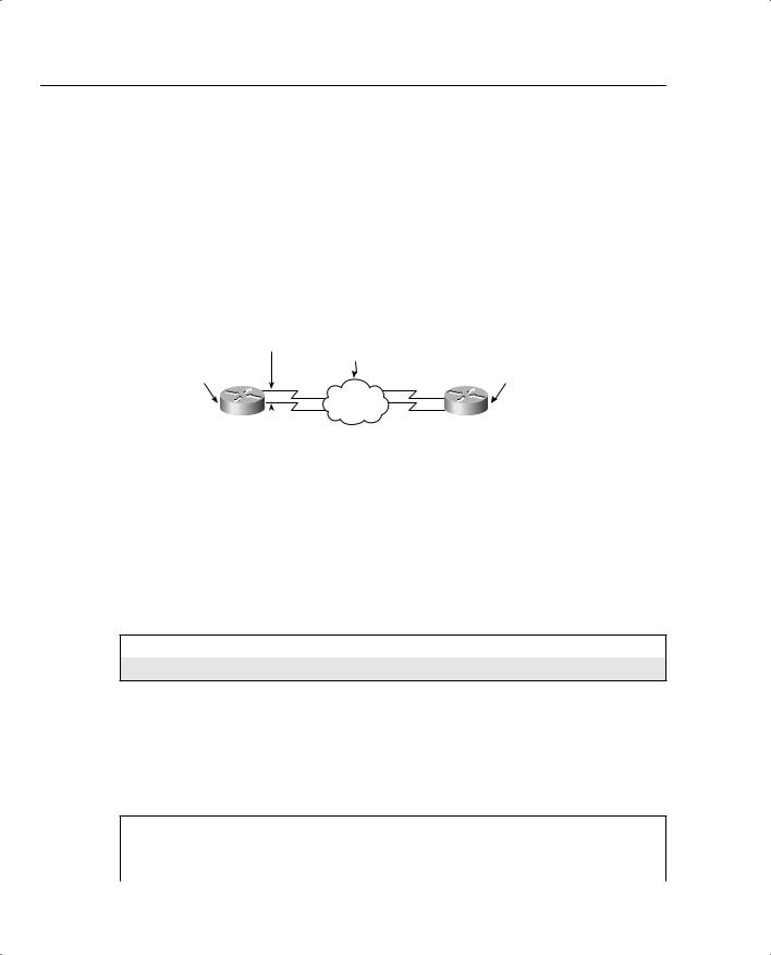
Configure a two-router EIGRP network with two Frame Relay links between two routers to demonstrate the redundancy mechanism with the EIGRP DUAL algorithm.
Figure 2-15 displays a two-router topology using the same addressing as the RIP example in Figure 2-14.
Figure 2-15 EIGRP Configuration Example
Autonomous System 100
(AS100)
Bandwidth
256131.108.3.0/30 Frame Relay
172.108.1.1/24 |
|
|
S0/0 |
|
S0/0 |
|
172.108.2.1/24 |
||
|
.1 |
|
.2 |
|
|||||
|
|
|
|
|
|
|
|||
|
|
|
|
|
|
|
|||
|
|
|
|
|
|
|
|
|
|
|
E0/0 |
R1 |
|
S0/1 |
|
S0/1 |
R2 |
E0/0 |
|
|
|
|
|
||||||
|
|
|
|
|
|
||||
|
|
|
.1 |
131.108.10.0/30 |
.2 |
|
|
||
|
|
|
|
|
|
|
|||
|
|
Bandwidth |
|
|
|
|
|||
|
|
Frame Relay |
|
|
|
|
|||
|
|
|
128 |
|
|
|
|
||
|
|
|
|
|
|
|
|
||
|
R1's Loopbacks |
|
|
|
R2's Loopbacks |
|
|
||
|
Loopback0 131.108.4.1/24 |
|
Loopback0 131.108.7.1/24 |
||||||
|
Loopback1 131.108.5.1/24 |
|
Loopback1 131.108.8.1/24 |
||||||
|
Loopback2 131.108.6.1/24 |
|
Loopback2 131.108.9.1/24 |
||||||
Routers R1 and R2 reside in AS 100, and to enable EIGRP on both routers, you need to start by configuring EIGRP. Example 2-15 displays the EIGRP configuration required on R1 and R2.
Example 2-15 Enabling EIGRP in AS 100
router eigrp 100
network 131.108.0.0
The network command in Example 2-15 enables EIGRP to send and receive updates for interfaces configured with the Class B address, 131.108.0.0. EIGRP will automatically summarize.
Example 2-16 displays the IP routing table on R1.
Example 2-16 show ip route on R1
R1#show ip route
Codes: C - connected, D - EIGRP, EX - EIGRP external, 131.108.0.0/16 is variably subnetted, 10 subnets, 2 masks
C 131.108.10.0/30 is directly connected, Serial0/1

Routing Protocols 65
Example 2-16 show ip route on R1 (Continued)
D131.108.9.0/24 [90/10639872] via 131.108.3.2, 00:04:27, Serial0/0
D131.108.8.0/24 [90/10639872] via 131.108.3.2, 00:04:27, Serial0/0
D131.108.7.0/24 [90/10639872] via 131.108.3.2, 00:04:27, Serial0/0 C 131.108.6.0/24 is directly connected, Loopback2
C 131.108.5.0/24 is directly connected, Loopback1 C 131.108.4.0/24 is directly connected, Loopback0 C 131.108.3.0/30 is directly connected, Serial0/0
D131.108.2.0/24 [90/10537472] via 131.108.3.2, 00:04:28, Serial0/0 C 131.108.1.0/24 is directly connected, Ethernet0/0
Example 2-16 displays four remote EIGRP entries (designated by D in the routing table) via the Serial interface Serial0/0. EIGRP has discovered these networks as the preferred path because the WAN bandwidth is 256 kbps as opposed to 128 kbps via Serial 0/1. To view the alternate paths, use the show ip eigrp topology IOS command to display backup paths.
Example 2-17 displays the output of the show ip eigrp topology command on R1.
Example 2-17 show ip eigrp topology on R1
R1#show ip eigrp topology
IP-EIGRP Topology Table for AS(100)/ID(131.108.6.1)
Codes: P - Passive, A - Active, U - Update, Q - Query, R - Reply, r - reply Status, s - sia Status
P 131.108.10.0/30, 1 successors, FD is 2169856 via Connected, Serial0/1
via 131.108.3.2 (11023872/1761792), Serial0/0 P 131.108.9.0/24, 1 successors, FD is 2297856
via 131.108.3.2 (10639872/128256), Serial0/0 via 131.108.10.2 (20640000/128256), Serial0/1
P 131.108.8.0/24, 1 successors, FD is 2297856
via 131.108.3.2 (10639872/128256), Serial0/0 via 131.108.10.2 (20640000/128256), Serial0/1
P 131.108.7.0/24, 1 successors, FD is 2297856
via 131.108.3.2 (10639872/128256), Serial0/0 via 131.108.10.2 (20640000/128256), Serial0/1
P 131.108.6.0/24, 1 successors, FD is 128256 via Connected, Loopback2
P 131.108.5.0/24, 1 successors, FD is 128256 via Connected, Loopback1
P 131.108.4.0/24, 1 successors, FD is 128256 via Connected, Loopback0
P 131.108.3.0/30, 1 successors, FD is 2169856 via Connected, Serial0/0
via 131.108.10.2 (21024000/1761792), Serial0/1 P 131.108.2.0/24, 1 successors, FD is 2195456
via 131.108.3.2 (10537472/281600), Serial0/0 via 131.108.10.2 (20537600/281600), Serial0/1
P 131.108.1.0/24, 1 successors, FD is 281600 via Connected, Ethernet0/0

66 Chapter 2: General Networking Topics
Example 2-17 shows that the remote network 131.108.2.0 is via two paths, and because the feasible distance is lower through Serial 0/0, that path is injected into the routing table. If, for some reason, the link with Serial 0/0 on R1 fails, the alternate path will be chosen and inserted into the routing table, increasing convergence times.
When EIGRP loses a path to a remote network, it sends requests to neighboring routers for alternative ways to reach the failed network. The neighboring router that returns the most favorable routes is called the feasible successor; in Figure 2-15, that router is R2.
NOTE The Cisco CD Documentation Codes State of this topology table entry are defined as follows:
•P (Passive)—No EIGRP computations are being performed for this destination.
•A (Active)—EIGRP computations are being performed for this destination.
•U (Update)—Indicates that an update packet was sent to this destination.
•Q (Query)—Indicates that a query packet was sent to this destination.
•R (Reply)—Indicates that a reply packet was sent to this destination.
•r (Reply status)—–A flag that is set after the software has sent a query and is waiting for a reply.
*Cisco Connection online was the source for this material, www.cisco.com/univercd/cc/td/doc/product/software/ios122/122cgcr/fiprrp_r/1rfeigrp.htm#1 025659.
OSPF
OSPF is a link-state routing protocol. Link-state protocols use Dijkstra’s shortest path first (SPF) algorithm to populate the routing table. OSPF shares information with every router in the network. OSPF is a classless protocol and supports VLSM. Table 2-11 defines common OSPF terminology.
OSPF in a Single Area
When configuring any OSPF router, you must establish what area assignment the interface will be enabled for. OSPF has some basic rules when it comes to area assignment. OSPF must be configured with areas. The backbone area 0, or 0.0.0.0, must be configured if you use more than one area assignment. If your OSPF design has only one area, it can have any number.

|
|
Routing Protocols 67 |
|
|
|
Table 2-11 Common OSPF Terms |
|
|
|
|
|
|
Term |
Description |
|
|
|
|
Hello packet |
Exchanged by the routers for neighbor discovery and forming adjacency, |
|
|
neighbor keep-alive, and DR/BDR election. |
|
|
|
|
Link state |
Information is shared between directly connected routers. This |
|
|
information propagates unchanged throughout the network and is also |
|
|
used to create a shortest path first (SPF) tree. |
|
|
|
|
Area |
A group of routers and links that share the same Area ID. All OSPF |
|
|
routers require area assignments. All routers within an area have the same |
|
|
database. Link state flooding is limited to an area. |
|
|
|
|
Autonomous system (AS) |
A network under a common network administration domain running |
|
|
common routing protocols. |
|
|
|
|
Cost (OSPF Metric) |
The routing metric used by OSPF. Lower costs are always preferred. You |
|
|
can manually configure the cost of an interface with the ip ospf cost |
|
|
command. By default, the cost is calculated by using the formula, cost = |
|
|
108/bandwidth. |
|
Router ID |
Each OSPF router requires a unique router ID, which is the highest IP |
|
|
address configured on a Cisco router or the highest-numbered loopback |
|
|
address. You can manually assign the router ID. |
|
|
|
|
Adjacency |
When two OSPF routers have exchanged information between each other |
|
|
and have the same topology table. Adjacency can have a number of states |
|
|
or exchange states: |
|
|
Init state—When Hello packets have been sent and are awaiting a reply |
|
|
to establish two-way communication. |
|
|
Establish bidirectional (two-way) communication—Accomplished by |
|
|
the discovery of the Hello protocol routers and the election of a DR. |
|
|
Exstart—Two neighbor routers form a master/slave relationship and |
|
|
agree upon a starting sequence that will be incremented to ensure that |
|
|
LSAs are acknowledged. |
|
|
Exchange state—Database Description (DD) packets continue to flow as |
|
|
the slave router acknowledges the master’s packets. OSPF is operational |
|
|
because the routers can send and receive LSAs between each other. DD |
|
|
packets contain information such as the router ID, area ID, checksum, if |
|
|
authentication is used, link-state type, and the advertising router. LSA |
|
|
packets also contain information such as router ID, and additionally |
|
|
include MTU sizes, DD sequence numbering, and any options. |
|
|
|
continues
68 Chapter 2: General Networking Topics
Table 2-11 Common OSPF Terms (Continued)
Term |
Description |
|
|
Adjacency (Continued) |
Loading state—Link-state requests are sent to neighbors asking for |
|
recent advertisements that have been discovered in Exchange state but not |
|
received. |
|
Full state—Neighbor routers are fully adjacent because their link-state |
|
databases are fully synchronized within the area. Routing tables begin to |
|
be populated. |
|
|
Topology table |
Also called the link-state table, this table contains every link in the entire |
|
network. |
|
|
Designated Router (DR) |
This router ensures adjacencies between all neighbors on a multiaccess |
|
network (such as Ethernet). This ensures that not all routers need to |
|
maintain full adjacencies with each other. |
|
The DR is selected based on the priority. In a tie, the router with the |
|
highest router ID is selected. |
|
|
Backup DR |
A Backup Designated Router is designed to perform the same functions in |
|
case the DR fails. |
|
|
Link-state advertisement |
A packet that contains all relevant information regarding a router’s links |
(LSA) |
and the state of those links. |
|
|
Priority |
Sets the router’s priority so a DR or BDR can be correctly elected. |
|
|
Router links |
Describe the state and cost of the router’s interfaces to the area. Router |
|
links use LSA type 1. |
|
|
Summary links |
Originated by Area Border Routers, these links describe networks in the |
|
AS. Summary links use LSA type 3 and 4. |
|
|
Network links |
Originated by DRs. Network links use LSA type 2. |
|
|
External links |
Originated by autonomous system boundary routers; they advertise |
|
destinations external to the AS or the default route external to the AS. |
|
|
Area Border Router |
Router located on the border of one or more OSPF areas to connect those |
(ABR) |
areas to the backbone network. |
|
|
Autonomous system |
An ABR located between an OSPF autonomous system and a non-OSPF |
boundary router (ASBR) |
network. |
|
|
The configuration steps to enable OSPF in a single area are as follows:
Step 1 Start OSPF with the command router ospf process ID. The process ID is locally significant to the router.
Step 2 Enable the interfaces with the network command. For example, to place the Network 131.108.1.0 in area 1, the IOS command is network 131.108.1.0 area 1.

Routing Protocols 69
Step 3 Identify area assignments.
Step 4 (Optional) Assign the router ID with the router-id router-id IOS command under the OSPF process.
NOTE The following is a list of reasons OSPF (link-state) is considered a better routing protocol than RIPv1 (distance vector):
•OSPF has no hop count limitation. (RIP has a limit of 15 hops only.)
•OSPF understands VLSM and allows for summarization.
•OSPF uses multicasts (not broadcasts) to send updates.
•OSPF converges much faster than RIP because OSPF propagates changes immediately. OSPF is faster because it sends the link update and then calculates the local routing table. RIP calculates the local routing table and then sends an update.
•OSPF allows for load balancing with up to six equal-cost paths.
•OSPF has authentication available (RIPv2 does also, but RIPv1 does not).
•OSPF allows tagging of external routes injected by other autonomous systems.
•OSPF configuration, monitoring, and troubleshooting have a far greater IOS tool base than RIP.
Multiple OSPF Areas
An OSPF area is a logical grouping of routers and links by a network administrator. OSPF routers in any area share the same topological view (also known as the OSPF or database) of the network. OSPF is configured in multiple areas to reduce routing table sizes, which in return, reduces the topological database and CPU/memory requirements on a router.
Routing tables become very large even with just 50 routers.
Cisco recommends no more than 50 routers per area. The OSPF database is exchanged in full every 30 minutes, and if this database is too large, every time this occurs, the amount of bandwidth used over the network increases and can cause severe delays in sending user-based traffic because convergence times are increased.
Areas allow OSPF designers to limit and confine changes. Additionally, a number of predefined areas types help reduce the demand on routers, as displayed in Table 2-12.

70 Chapter 2: General Networking Topics
Table 2-12 Additional Area Types
Area Type |
Function |
|
|
Stubby area |
This area does not accept LSA types 4 and 5, which are summary links and |
|
external link advertisements, respectively. The only way to achieve a route to |
|
unknown destinations is a default route injected by the ABR. |
|
|
Totally stubby area |
This area blocks LSA types 3, 4, and 5. Only a single type 3 LSA advertising |
|
the default route is allowed. This solution is Cisco proprietary and is used to |
|
further reduce a topological database. |
|
|
Not-so-stubby area |
This area is used primarily for connections to an ISP. This area is designed to |
(NSSA) |
allow type 7 LSAs only. All advertised routes can be flooded through the NSSA |
|
but are blocked by the ABR. Basically, a type 7 LSA (if the P bit is set to one) |
|
is converted to a type 5 LSA and flooded through the rest of the network. If the |
|
P bit is set to 0, no translation will take place. Type 4 or 5 LSAs are not |
|
permitted. This advertisement will not be propagated to the rest of the network. |
|
NSSAs typically provide a default route. |
|
|
Table 2-13 defines the challenges across various media types, such as Frame Relay and broadcast media.
Table 2-13 OSPF over Various Media Types Using Cisco IOS Software
Method |
Description |
|
|
Point-to-point nonbroadcast |
Used typically for Frame Relay interfaces. |
|
|
Point-to-point |
This is the default mode for subinterfaces. |
|
|
Point-to-multipoint |
Used for multiple destinations. |
|
|
Nonbroadcast |
Nonbroadcast multiaccess (NBMA) mode. |
|
|
Broadcast |
Used in Ethernet and broadcast environments where the election of |
|
DR/BDR takes place. To define the DR, use the IOS command ip ospf |
|
priority priority-number. The priority-number is 1 to 255. The highest |
|
priority will be to elect the DR. |
|
|
Ethernet is an example of where OSPF will elect a DR to minimize the OSPF updates over a broadcast medium. Each multiaccess OSPF network that has at least two attached routers has a designated router elected by the OSPF Hello protocol. The DR enables a reduction in the number of adjacencies required on a multiaccess network, which reduces the amount of routing protocol traffic and the size of the topological database, especially when more than two routers are deployed on this network segment.
Routing Protocols 71
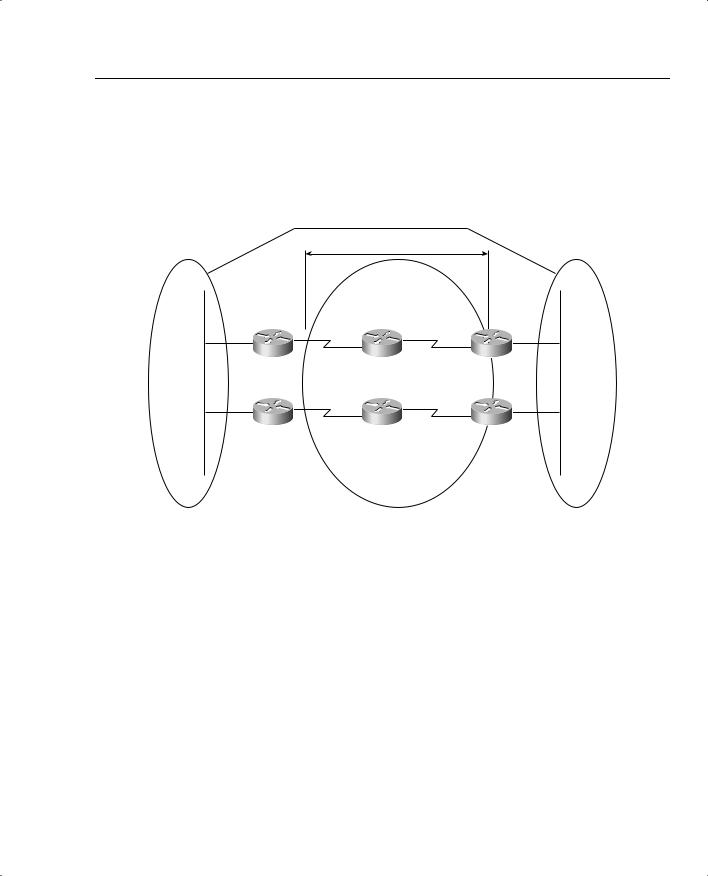
Virtual Links
All OSPF areas must be connected to the backbone area (Area 0). Figure 2-16 demonstrates a topology where an area (Area 100) is not directly connected to the backbone.
Figure 2-16 OSPF Area Assignment
Virtual Link or New WAN circuit required
Transit Area (200)
Router A |
Router B |
Router C
Router D
Router F |
Router E |
Area 0 |
Area 200 |
Area 100 |
or |
|
|
Backbone |
|
|
To ensure that Area 100 is reachable by the backbone, a virtual link can be configured over the transit area (200), and IP connectivity will be maintained. Virtual links are typically used in a transition phase (for example, when one company buys another and both companies use OSPF). Another solution to the problem depicted in Figure 2-16 is to install a physical link between Router C or Router D and the backbone core network.
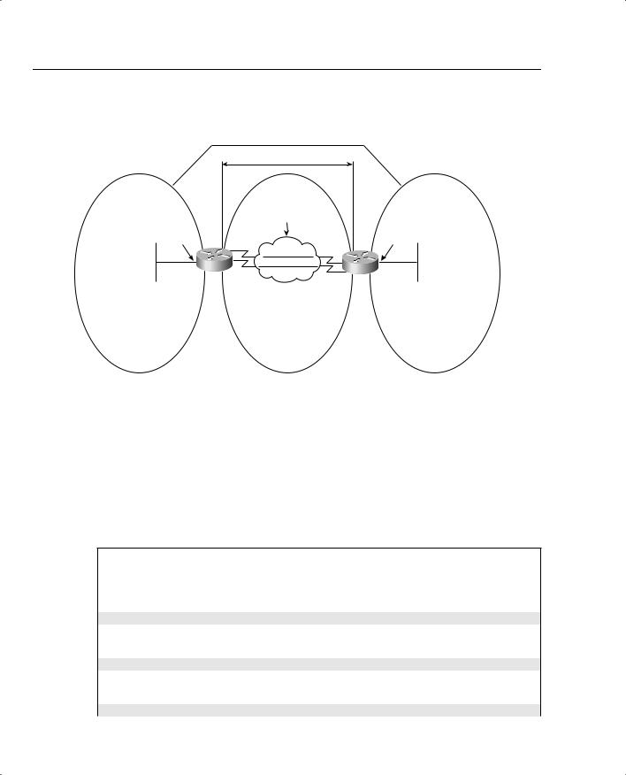
OSPF Configuration Example
Figure 2-17 demonstrates a two-router topology. Figure 2-17 displays three OSPF areas with Area 2 partitioned from the backbone, necessitating a virtual link.
72 Chapter 2: General Networking Topics
Figure 2-17 Typical Cisco IOS OSPF topology
Virtual Link Required
Transit Area
Area 0 |
Area 1 |
Area 2 |
131.108.225.0/30 Frame Relay
131.108.1.1/24
E0/0
|
S0/0 |
S0/0 |
|
|
|
.1 |
PVC#1 |
.2 |
|
|
|
|
|
|
|
|
PVC#2 |
|
|
|
|
F/R |
|
|
R1 |
S0/1 |
S0/1 |
R2 |
|
|
.5 |
131.108.255.4/3 |
.6 |
|
|
|
0 |
|
|
|
|
Frame Relay |
|
|
|
|
Point-to-point |
|
|
|
|
network 256 |
|
|
|
|
Kb for each PVC |
|
|
172.108.2.1/24
E0/0
R1's Loopbacks in Area 0 |
R2's Loopbacks in Area 1 |
Loopback0 131.108.2.1/24 |
Loopback0 131.108.9.1/24 |
Loopback1 131.108.3.1/24 |
Loopback1 131.108.10.1/24 |
Loopback2 131.108.4.1/24 |
Loopback2 131.108.11.1/24 |
Loopback3 131.108.5.1/24 |
Loopback3 131.108.12.1/24 |
Loopback4 131.108.6.1/24 |
Loopback4 131.108.13.1/24 |
Loopback5 131.108.7.1/24 |
Loopback5 131.108.14.1/24 |
|
Loopback6 131.108.15.1/24 |
Example 2-18 displays the full working configuration of R1.
Example 2-18 R1’s OSPF Configuration
!
hostname R1
enable password cisco interface Loopback0
ip address 131.108.2.1 255.255.255.0 ip ospf network point-to-point
!
interface Loopback1
ip address 131.108.3.1 255.255.255.0 ip ospf network point-to-point
!
interface Loopback2
ip address 131.108.4.1 255.255.255.0 ip ospf network point-to-point

Routing Protocols 73
Example 2-18 R1’s OSPF Configuration (Continued)
!
interface Loopback3
ip address 131.108.3.1 255.255.255.0 ip ospf network point-to-point
!
interface Loopback4
ip address 131.108.6.1 255.255.255.0 ip ospf network point-to-point
!
interface Loopback5
ip address 131.108.7.1 255.255.255.0 ip ospf network point-to-point
!
interface Ethernet0/0
ip address 131.108.1.1 255.255.255.0
!
interface Serial0/0 bandwidth 256
ip address 131.108.255.1 255.255.255.252 encapsulation frame-relay
ip ospf network point-to-point
!
interface Serial0/1 bandwidth 256
ip address 131.108.255.5 255.255.255.252 encapsulation frame-relay
ip ospf network point-to-point
!
router ospf 1 router-id 131.108.7.1
area 1 virtual-link 131.108.15.1 network 131.108.0.0 0.0.7.255 area 0
network 131.108.255.0 0.0.0.3 area 0
network 131.108.255.4 0.0.0.3 area 0
!
end
By default, loopback interfaces are stub hosts in OSPF and are advertised as 32-bit hosts. The IOS command ip ospf network point-to-point advertises the loopback networks as /24 networks (in this case, you use /24 subnet mask). The Frame Relay connection is configured as point-to-point to ensure that no manual OSPF neighbor configuration is required to form OSPF neighbors. The virtual link is configured across the transit area, 1, to R2 router ID of 131.108.14.1.

74 Chapter 2: General Networking Topics
Example 2-19 displays R2’s full working configuration.
Example 2-19 R2’s OSPF Configurations
hostname R2
enable password cisco interface Loopback0
ip address 131.108.9.1 255.255.255.0 ip ospf network point-to-point
!
interface Loopback1
ip address 131.108.10.1 255.255.255.0 ip ospf network point-to-point
!
interface Loopback2
ip address 131.108.11.1 255.255.255.0 ip ospf network point-to-point
!
interface Loopback3
ip address 131.108.12.1 255.255.255.0 ip ospf network point-to-point
!
interface Loopback4
ip address 131.108.13.1 255.255.255.0 ip ospf network point-to-point
!
interface Loopback5
ip address 131.108.14.1 255.255.255.0 ip ospf network point-to-point
!
interface Loopback6
ip address 131.108.15.1 255.255.255.0 ip ospf network point-to-point
!
interface Ethernet0/0
ip address 131.108.8.1 255.255.255.0 half-duplex
!
interface Serial0/0
ip address 131.108.255.2 255.255.255.252 encapsulation frame-relay
ip ospf network point-to-point
interface Serial0/1
ip address 131.108.255.6 255.255.255.252 encapsulation frame-relay
ip ospf network point-to-point
!
router ospf 1
router-id 131.108.15.1
area 1 virtual-link 131.108.7.1 network 131.108.8.0 0.0.0.255 area 2 network 131.108.9.0 0.0.0.255 area 1

Routing Protocols 75
Example 2-19 R2’s OSPF Configurations (Continued)
network 131.108.10.0 0.0.0.255 area 1 network 131.108.11.0 0.0.0.255 area 1 network 131.108.12.0 0.0.0.255 area 1 network 131.108.13.0 0.0.0.255 area 1 network 131.108.14.0 0.0.0.255 area 1 network 131.108.15.0 0.0.0.255 area 1 network 131.108.255.0 0.0.0.3 area 0 network 131.108.255.4 0.0.0.3 area 0
end
Example 2-20 displays the IP OSPF routing table on R1.
Example 2-20 show ip route ospf on R1
R1#show ip route ospf
131.108.0.0/16 is variably subnetted, 17 subnets, 2 masks
O131.108.15.0/24 [110/391] via 131.108.255.6, 00:00:41, Serial0/1
[110/391] via 131.108.255.2, 00:00:41, Serial0/0
O131.108.14.0/24 [110/391] via 131.108.255.6, 00:00:41, Serial0/1
[110/391] via 131.108.255.2, 00:00:41, Serial0/0
O131.108.13.0/24 [110/391] via 131.108.255.6, 00:00:41, Serial0/1
[110/391] via 131.108.255.2, 00:00:41, Serial0/0
O131.108.12.0/24 [110/391] via 131.108.255.6, 00:00:41, Serial0/1
[110/391] via 131.108.255.2, 00:00:41, Serial0/0
O131.108.11.0/24 [110/391] via 131.108.255.6, 00:00:41, Serial0/1
[110/391] via 131.108.255.2, 00:00:41, Serial0/0
O131.108.10.0/24 [110/391] via 131.108.255.6, 00:00:41, Serial0/1
[110/391] via 131.108.255.2, 00:00:41, Serial0/0
O131.108.9.0/24 [110/391] via 131.108.255.6, 00:00:41, Serial0/1
|
[110/391] via 131.108.255.2, 00:00:42, Serial0/0 |
||
O IA |
131.108.8.0/24 [110/400] via 131.108.255.6, |
00:00:42, |
Serial0/1 |
|
[110/400] via 131.108.255.2, |
00:00:42, |
Serial0/0 |
R1’s routing table has the remote OSPF networks labeled as O IA because the network 131.108.8.0/24 is part of an area not directly attached to R1. Also, R1 is automatically load balancing across the two paths because the cost metric is the same (391). The administrative distance is 110 (the default).
NOTE The election of the designated router in networks such as Frame Relay is important, and you must ensure the hub or core network router is the elected DR so that the hub router disseminates information to all spoke routers. To ensure the hub is the DR, you can disable the DR election process on edge routers with the IOS command, ip ospf priority 0.

76 Chapter 2: General Networking Topics
Border Gateway Protocol
Border Gateway Protocol (BGP) is an exterior routing protocol used widely in the Internet. It is commonly referred to as BGP4 (version 4).
BGP4 is defined in RFC 1771. BGP allows you to create an IP network free of routing loops between different autonomous systems.
An autonomous system (AS) is a set of routers under the same administrative control.
BGP is called a path vector protocol because it carries a sequence of AS numbers that indicates the path taken to a remote network. This information is stored so that routing loops can be avoided.
BGP uses TCP as its Layer 4 protocol (TCP port 179). No other routing protocol in use today relies on TCP. This allows BGP to make sure that updates are sent reliably, leaving the routing protocol to concentrate on gathering information about remote networks and ensuring a loopfree topology.
Routers configured for BGP are typically called BGP speakers, and any two BGP routers that form a BGP TCP session are called BGP peers or BGP neighbors.
BGP peers initially exchange full BGP routing tables. After the exchange, only BGP updates are sent between peers, ensuring that only useful data is sent unless a change occurs.
Four message are types used in BGP4 to ensure that peers are active and updates are sent:
•Open Messages—Used when establishing BGP peers.
•Keepalives—These messages are sent periodically to ensure connections are still active or established.
•Update messages—Any changes that occur, such as a loss of network availability, result in an update message.
•Notification—Only used to notify BGP peers of any receiving errors.
Key BGP characteristics include the following:
•BGP is a path vector protocol.
•BGP uses TCP as the transport layer protocol.
•Full routing table is exchanged only during initial BGP session.
•Updates are sent over TCP port 179.
•BGP sessions are maintained by keepalive messages.
•Any network changes result in update messages.
•BGP has its own BGP table. Any network entry must reside in the BGP table first.
•BGP has a complex array of metrics, such as next-hop address and origin, which are called attributes.
•BGP supports VLSM and summarization (sometimes called Classless Interdomain Routing [CIDR]).

Routing Protocols 77
BGP4’s ability to guarantee routing delivery and the complexity of the routing decision process mean that BGP will be widely used in any large IP routing environment, such as the Internet. The Internet consists of over 100,000 BGP network entries, and BGP is the only routing protocol available today that can handle and manage such a large routing table. The Internet (80,000+ routes) could not be functional today if BGP were not the routing protocol in use.
Before covering some simple examples, the next section describes BGP attributes.
BGP Attributes
BGP has a number of complex attributes that determine a path to a remote network. These attributes allow a greater flexibility and complex routing decision to ensure a path to a remote network is taken by the best path possible.
The network designer can also manipulate these attributes. BGP, when supplied with multiple paths to a remote network, will always choose a single path to a specific destination. (Load balancing is possible with static routes.) BGP always propagates the best path to any peers.
BGP attributes are carried in update packets.
Table 2-14 describes the well-known and optional attributes used in BGP4.
Table 2-14 Well-Known and Optional Attributes
Attribute |
Description |
|
|
Origin |
This attribute is mandatory, defines the source of the path, and can |
|
be three different values: |
|
IGP—Originating from interior of the AS. |
|
EGP—Learned through an External Gateway Protocol. |
|
Incomplete—The BGP route was discovered using redistribution |
|
or static routers. |
|
|
AS_Path |
Describes the sequences of AS that the packet has traversed to the |
|
destination IP network. |
|
|
Next Hop |
Describes the next-hop address taken to a remote path, typically |
|
the eBGP peer. |
|
|
Local Preference |
Indicates the preferred path to exit the AS. A higher local |
|
preference is always preferred. |
|
|
Multi Exit Discriminator (MED) |
Informs BGP peers in other autonomous systems about which |
|
path to take into the AS when multiple autonomous systems are |
|
connected. A lower MED is always preferred. |
|
|
continues
78 Chapter 2: General Networking Topics
Table 2-14 Well-Known and Optional Attributes (Continued)
Attribute |
Description |
|
|
Weight |
Cisco-defined, attribute-only attribute that is used in local router |
|
selection. Weight is not sent to other BGP peers, and higher |
|
weight value is always preferred. Weight is locally significant to |
|
the router and specifies a preferred path when more than one path |
|
exists. Cisco-only attribute. |
|
|
Atomic Aggregate |
Advises BGP routers that aggregation has taken place. Not used in |
|
router selection process. |
|
|
Aggregator |
The router ID responsible for aggregation; not used in the router |
|
selection process. |
|
|
Community |
Allows routes to be tagged and use a group of routes sharing the |
|
same characteristics. An ISP typically tags traffic from customers |
|
along with a route-map to modify the community attribute. |
|
|
Originator ID |
Prevents routing loops. This information is not used for router |
|
selection. |
|
|
Cluster-List |
Used in a route-reflectors environment. This information is not |
|
used for router selection. |
|
|
There are two types of BGP sessions: internal BGP (IBGP) and external BGP (EBGP). IBGP is a connection between two BGP speakers in the same AS. EBGP is a connection between two BGP speakers in different autonomous systems.
IBGP peers also make sure that routing loops cannot occur by ensuring that any routes sent to another AS must be known via an interior routing protocol, such as OSPF, before sending that information. That is, the routers must be synchronized. The benefit of this added rule in IBGP TCP sessions is that information is not sent unless it is reachable, which reduces any unnecessary traffic and saves bandwidth. Route reflectors in IBGP ensure that large internal BGP networks do not require a fully meshed topology. Route reflectors are not used in EBGP connection. A BGP route reflector disseminates routing information to all route-reflector clients, and ensures that BGP tables are sent and that a fully meshed IBGP need not be configured.
The BGP routing decision is quite complex and takes several attributes into account. The attributes and process taken by a Cisco router running BGP4 are as follows:
1If the next-hop address is reachable, consider it.
2Prefer the route with the highest weight (Cisco IOS routers only).
3If the weight is the same, prefer the largest local preference attribute.
4If the local preference is the same, prefer the route originated by this local router (routes generated by network or redistribute commands).