

Internet Protocol 33
NOTE A group of bundled ports running FEC is commonly known as a trunk. In switching terms, a trunk is a physical and logical connection between two switches.
Inter-Switch Link (ISL) is a Cisco proprietary protocol that maintains VLAN information as traffic flows between switches and routers. ISL allows members of one VLAN to be located on any given switch. 802.1Q is an IEEE standard for trunking. You can use IEEE 802.1q in a multivendor environment.
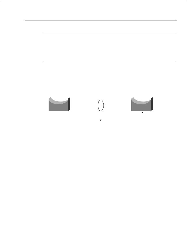
Figure 2-5 displays the logical link when FEC is enabled between Switch A and Switch B.
Figure 2-5 FEC: Logical Link or Trunk-Enabled
Set port channel 1/1 on |
|
|
Set port channel 1/1 on |
|||
Set port channel 1/2 on |
|
|
Set port channel 1/2 on |
|||
|
1/1 Forwarding |
|
Forwarding 1/1 |
|||
|
|
|
|
|
|
|
|
|
|
|
|
|
|
|
1/2 Forwarding |
|
Forwarding 1/2 |
|||
|
|
|||||
|
|
|
|
|
|
|
|
|
|
|
|
|
|
|
Ports are bundled together; |
Both ports forwarding |
||||
|
effective bandwidth now up |
|
now when FEC |
|||
|
to 400 Mbps at full duplex |
|
is configured. |
|||
|
instead of 200 Mbps. |
|
|
|
||
Internet Protocol
Internet Protocol (IP) is a widely used networking term that describes a network layer protocol that logically defines a distinct host or end system, such as a PC or router, with an IP address.
An IP address is configured on end systems to allow communication between hosts over wide geographic locations. An IP address is 32 bits in length, with the network mask or subnet mask (also 32 bits in length) defining the host and subnet portion.
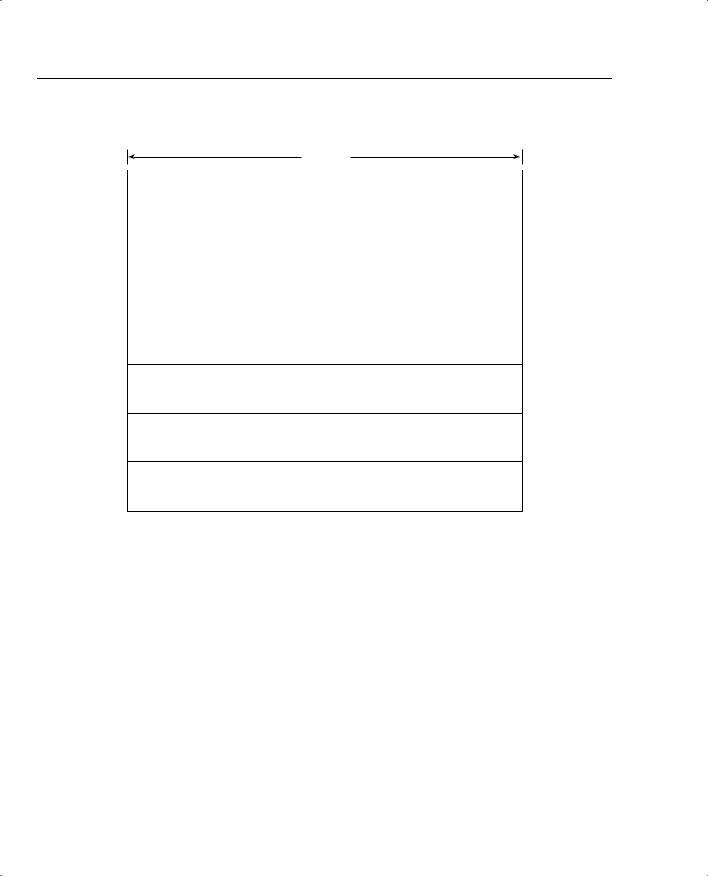
Figure 2-6 displays the IP packet header frame format in detail.
34 Chapter 2: General Networking Topics
Figure 2-6 IP Frame Format
32 bits
Version |
IML |
|
Type of Service |
|
Total Length |
|
|
|
|
|
|
|
|
|
Identification |
|
Flags |
|
Fragment Offset |
|
|
|
|
|
|
|
|
Time-To-Live |
|
Protocol |
Header Checksum |
|||
|
|
|
|
|
|
|
Source Address (32 bits)
Destination Address (32 bits)
Options (+ Padding)
Data (Variable)
The following describes the IP packet fields illustrated in Figure 2-6:
•Version—Indicates the version of IP currently used. IPv4 is the most widely used version. IPv6 is also available. This version is not tested in the CCIE Security written exam yet, but will most likely be included in the future.
•IP Header Length (IHL)—Indicates the datagram header length in 32-bit words.
•Type-of-Service (ToS)—Specifies how an upper-layer protocol wants current datagrams to be handled and assigns datagrams various levels of importance. The ToS field (8 bits) defines the first 3 bits for precedence, of which there are eight possible values:
—000—Routine delivery
—001—Priority
—010—Immediate
—011—Flash
—100—Flash override
Internet Protocol 35
—101—Critic
—110—Internetwork control
—111—Network control
Typically, IP packets are set with the value 000. The remaining 5 bits in the ToS are defined as follows:
—Bit 3—D bit defines normal or low delay.
—Bit 4—T bit defines normal or low throughput.
—Bit 5—R bit defines normal or low reliability.
—Bits 6 and 7—Not in current use.
•Total Length—Specifies the entire packet’s length in bytes, including the data and header. The mathematically defined limit is calculated as 65,535 bytes (216–1).
•Identification—Contains an integer that identifies the current datagram. This field helps piece together datagram fragments (16 bits in length).
•Flags—Consists of a 3-bit field of which the two low-order (least-significant) bits control fragmentation. The low-order bit specifies whether the packet can be fragmented. The middle bit specifies whether the packet is the last fragment in a series of fragmented packets. The third, or high-order, bit is not used.
•Fragment Offset—Indicates the position of the fragment’s data relative to the beginning of the data in the original datagram, which allows the destination IP process to properly reconstruct the original datagram.
•Time-to-Live—Maintains a counter that gradually decrements to 0, at which point the datagram is discarded. This keeps packets from looping endlessly. Cisco’s implementation of the Cisco IOS Trace command works on TTL.
•Protocol—Indicates which upper-layer protocol receives incoming packets after IP processing is complete. For TCP, this value is 6; for GRE, it is 47; for ICMP, it is 1; and for OSPF, the value is 89; these are common uses in today’s networks.
•Header Checksum—Helps ensure IP header integrity only and not the data field.
•Source Address—Specifies the sending node (32 bits).
•Destination Address—Specifies the receiving node (32 bits).
•Options—Allows IP to support various options, such as security. The Option field varies in length. Some options are Security, Loose Source Routing, Strict Source Routing, Record Route, and Timestamp.
•Data—Contains upper-layer information.
36 Chapter 2: General Networking Topics
NOTE A subnet is a network that is segmented by network administrators, allowing a hierarchical routing topology. Subnetting allows great use of IP address space using binary bits from the subnet mask. Examples of subnets appear later in this chapter.
Routing allows communication between these subnets. The host address is a logical, unique address that resides on a subnet.
The Internet Engineering Task Force (IETF) standards body, which is a task force consisting of over 80 working groups responsible for developing Internet standards, has defined five address classes and the appropriate address ranges. Table 2-3 displays the five ranges.
Table 2-3 |
Class A, B, C, D, and E Ranges |
|
|
|
|
|
|
|
|
|
Class of Address |
Starting Bit Pattern |
Range |
Default Subnet Mask |
|
|
|
|
|
|
Class A |
0xxxxxxx |
1-126, 127* |
255.0.0.0 |
|
|
|
|
|
|
Class B |
10xxxxxx |
128-191 |
255.255.0.0 |
|
|
|
|
|
|
Class C |
110xxxxx |
192-223 |
255.255.255.0 |
|
|
|
|
|
|
Class D |
1110xxxx |
224-239 |
255.255.255.240 |
|
|
|
|
|
|
Class E |
1111xxxx |
240-255 |
Reserved |
|
|
|
|
|
*127.0.0.0 is reserved for loopback purposes. Other reserved addresses for private use as defined by RFC 1918 are as follows:
10.0.0.0-10.255.255.255 172.16.0.0-172.31.255.255 192.168.0.0-192.168.255.255
Soon after these ranges were defined and the Internet’s popularity extended beyond the Department of Defense in the United States, it became clear that to ensure that a larger community could connect to the World Wide Web, there had to be a way to extend IP address space using subnetting. Subnetting allows an administrator to extend the boundary for any given subnet.
To understand an IP address and subnet portion, to determine how many hosts are available on a particular subnet, to learn how to best utilize an IP address space, consider the following example.
Suppose you are given the IP address 131.108.1.56 and the subnet mask is 255.255.255.0. This example will help you determine the subnet, how many hosts can reside on this subnet, and the broadcast address.
You can deduce the subnet for any IP address by performing a logical AND operation for the IP address along with the subnet mask.

Internet Protocol 37
NOTE |
A logical AND operation follows two basic rules. One is that positive and positive equal |
|
positive, and the second is that negative and either positive or negative equal negative. In binary |
|
(positive is 1 and negative is 0), 0 AND 0 is 0, 0 AND 1 is 0, 1 AND 1 is 1, and 1 AND 0 is 0. |
|
|
Figure 2-7 displays the logical AND operation used to determine the subnet address.
Figure 2-7 Logical AND Operation
IP Address (131.108.1.56) |
10000011.11001100.00000001.00111000 |
|||
IP Subnet Mask (255.255.255.0) |
11111111.11111111.11111111.00000000 |
|||
Logical AND |
10000011.11001100.00000001.00000000 |
|||
In Decimal |
131 |
108 |
1 |
0 |
The result of the logical AND operation reveals that the subnet address is 131.108.1.0. The subnet address is reserved and cannot be assigned to end devices.
To determine the number of hosts available in any given subnet, simply apply the formula 2n–2, where n is the number of borrowed bits. This is best explained with examples. To determine the number of borrowed bits, you must examine the subnet mask in binary. For a default Class C network mask of 255.255.255.0, the last 8 bits represent the borrowed bits. For a Class C network, the number of hosts that can reside are 28–2 = 256–2 = 254 hosts. You subtract 2 host addresses because host devices are not permitted to use the subnet address or the broadcast address. In IP, a broadcast address consists of all binary 1s. So, for this example, the broadcast address for the subnet 131.108.1.0 is 131.108.1.255 (255 in binary is 11111111).
Consider another example. Given the host address 171.224.10.67 and the subnet mask of 255.255.255.224, this example shows you how to determine the subnet and the number of hosts that can reside on this network.
To determine the subnet, perform a logical AND. Figure 2-8 displays the operation.
Figure 2-8 LOGICAL AND Operation
IP Address (171.224.10.67) |
10101011. 11100000. 00001 |
010. 01000011 |
||
IP Subnet Mask (255.255.255.224) |
11111111. 11111111. 11111 |
111. 11100000 |
||
Logical AND |
10101011. 11100000. 00001 |
010. 01000000 |
||
In Decimal |
171 |
224 |
10 |
64 |
The subnet is 171.224.10.64. The number of hosts that can reside on this network with a subnet mask of 255.255.255.224 (or 11100000, 5 borrow bits) is 25–2 = 32–2 = 30 hosts.You can apply this simple example to any Class A, B, or C address, and applying a subnet mask that is not the