

TWO-STROKE ENGINES |
Chapter 19 |
Meshing with the Trimming Method |
|
|
|
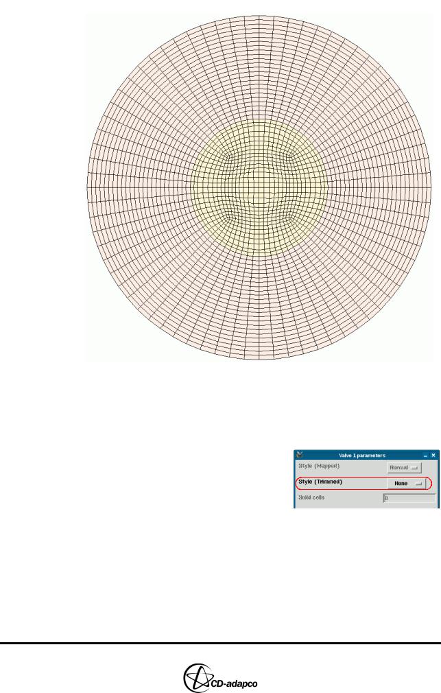
Figure 19-8 Two-stroke 2D template
Creating the 3D template
With the 2D template complete, you can now begin creating the 3D template. First, enter appropriate Valve parameters for an engine with no poppet valves:
•In the Create Template panel, select Valve 1 from the Valves drop-down menu
•In the Valve 1 parameters panel, set Style (Trimmed) to None from the drop-down menu to specify no poppet valves in the engine
•Click Ok to accept the settings and close the panel
Next, define Cylinder and Trim properties for the 3D template:
•In the Create Template panel, click Cylinder
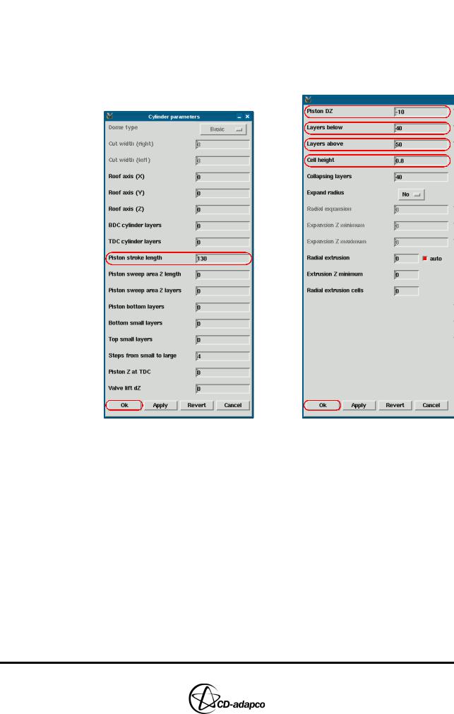
•In the Cylinder parameters panel, set the Piston stroke length to 130 to define the piston position at BDC
•Click Ok to accept the settings, shown on the left-hand side of Figure 19-9
•In the Create Template panel, click Trim
19-8 |
Version 4.20 |
Chapter 19 |
TWO-STROKE ENGINES |
|
Meshing with the Trimming Method |
|
|
•In the Trim parameters panel, set Piston DZ to -10 (see Table 4-14 in the User Guide for a definition of this and other Trim parameters)
•Set the Layers below to 40
•Set the Layers above to 50
•Set the Cell height to 0.8
•Click Ok to accept the settings, shown on the right-hand side of Figure 19-9
Figure 19-9 Two-stroke Cylinder parameters and Trim parameters
Finally, create the 3D template and read it into es-ice. You should also check that the template is suitable for trimming to the engine geometry.
•In the Create Template panel, click Make Template to create the 3D template
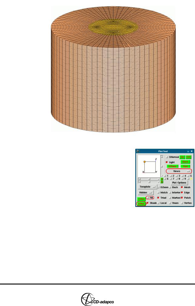
•When the child process is complete, click Read Template to read the 3D template into the Template panel, as shown in Figure 19-10
Version 4.20 |
19-9 |
TWO-STROKE ENGINES |
Chapter 19 |
Meshing with the Trimming Method |
|
|
|
Figure 19-10 Two-stroke 3D template
•In the Plot Tool, deselect the Fill toggle button to display the template as a transparent wire-frame plot
•Set the Views option to View 0 1 0
• Click DPlot to plot the 3D template on top of the engine geometry
Figure 19-11 shows that the template is suitable for trimming as it covers the entire engine volume.
19-10 |
Version 4.20 |
Chapter 19 |
TWO-STROKE ENGINES |
|
Meshing with the Trimming Method |
|
|
Figure 19-11 Two-stroke template and geometry DPlot
Trimming the 3D template to the geometry
You can now trim the 3D template to the engine geometry to produce a mesh for the engine cylinder’s internal volume:
•In the Select panel, click Trimming to open the Trim panel
•Click Cut to begin trimming the template to the engine geometry
•When the child process is complete, check that Cylinder is selected and then click Get to read the trimmed cylinder template into the Template panel
•In the Plot Tool, select the Fill option, click CPlot and adjust the view to display the trimmed template as shown in Figure 19-12
Version 4.20 |
19-11 |