![](/user_photo/2706_HbeT2.jpg)
- •TABLE OF CONTENTS
- •Chapter 1 INTRODUCTION
- •The es-ice Environment
- •es-ice Meshing Capabilities
- •Tutorial Structure
- •Trimming Tutorial Overview
- •Required Files
- •Trimming Tutorial files
- •Automatic 2D Tutorial files
- •Wall Temperature Tutorial files
- •Mesh Replacement Tutorial files
- •Multiple Cylinder Tutorial files
- •Closed-Cycle Tutorial files
- •Sector Tutorial files
- •Two-Stroke Tutorial files
- •Mapping Tutorial files
- •ELSA Tutorial files
- •Chapter 2 SURFACE PREPARATION IN STAR-CCM+
- •Importing and Scaling the Geometry
- •Creating Features
- •Defining Surfaces
- •Remeshing and Exporting the Geometry
- •Chapter 3 GEOMETRY IMPORT AND VALVE WORK
- •Importing the Surfaces
- •Modelling the Valves
- •Saving the Model
- •Chapter 4 MESHING WITH THE TRIMMING METHOD
- •Modifying Special Cell Sets in the Geometry
- •Defining Flow Boundaries
- •Creating the 2D Base Template
- •Creating the 3D Template
- •Trimming the 3D Template to the Geometry
- •Improving cell connectivity
- •Assembling the Trimmed Template
- •Running Star Setup
- •Saving the Model
- •Chapter 5 CREATING AND CHECKING THE MESH
- •Chapter 6 STAR SET-UP in es-ice
- •Load Model
- •Analysis Set-up
- •Valve Lifts
- •Assembly
- •Combustion
- •Initialization
- •Cylinder
- •Port 1 and Port 2
- •Boundary Conditions
- •Cylinder
- •Port and Valve 1
- •Port and Valve 2
- •Global settings
- •Post Set-up
- •Cylinder
- •Port 1 and Port 2
- •Global settings
- •Time Step Control
- •Write Data
- •Saving the Model
- •Chapter 7 STAR SET-UP in pro-STAR
- •Using the es-ice Panel
- •Setting Solution and Output Controls
- •File Writing
- •Chapter 8 RUNNING THE STAR SOLVER
- •Running in Serial Mode
- •Running in Parallel Mode
- •Running in Parallel on Multiple Nodes
- •Running in Batch
- •Restarting the Analysis
- •Chapter 9 POST-PROCESSING: GENERAL TECHNIQUES
- •Creating Plots with the es-ice Graph Tool
- •Calculating Apparent Heat Release
- •Plotting an Indicator Diagram
- •Calculating Global Engine Quantities
- •Creating a Velocity Vector Display
- •Creating an Animation of Fuel Concentration
- •Creating an Animation of Temperature Isosurfaces
- •Chapter 10 USING THE AUTOMATIC 2D TEMPLATE
- •Importing the Geometry Surface
- •Defining Special Cell Sets in the Geometry
- •Modelling the Valves
- •Creating the Automatic 2D Template
- •Refining the 2D Template Around the Injector
- •Adding Features to the Automatic 2D Template
- •Using Detailed Automatic 2D Template Parameters
- •Saving the es-ice Model File
- •Chapter 11 MULTIPLE-CYCLE ANALYSIS
- •Setting Up Multiple Cycles in es-ice
- •Setting Up Multiple Cycles in pro-STAR
- •Chapter 12 HEAT TRANSFER ANALYSIS
- •Resuming the es-ice Model File
- •Mapping Wall Temperature
- •Exporting Wall Heat Transfer Data
- •Saving the es-ice Model File
- •Cycle-averaging Wall Heat Transfer Data
- •Post-processing Wall Heat Transfer Data in pro-STAR
- •Plotting average wall boundary temperatures
- •Plotting average heat transfer coefficients
- •Plotting average near-wall gas temperature at Y-plus=100
- •Mapping Heat Transfer Data to an Abaqus Model via STAR-CCM+
- •Chapter 13 MESH REPLACEMENT
- •Preparing the File Structure
- •Rebuilding the Dense Mesh
- •Creating Ahead Files for the Dense Mesh
- •Defining Mesh Replacements
- •Setting Up Mesh Replacement in pro-STAR
- •Setting up the coarse model
- •Setting up the dense model
- •Chapter 14 MULTIPLE CYLINDERS
- •Resuming the es-ice Model File
- •Making, Cutting and Assembling the Template
- •Setting Up Multiple Cylinders
- •Checking the Computational Mesh
- •STAR Set-Up in es-ice
- •Analysis set-up
- •Assembly
- •Combustion
- •Initialization
- •Boundary Conditions
- •Post Setup
- •Time Step Control
- •Write Data
- •Saving the es-ice Model File
- •Importing the Geometry
- •Generating the Closed-Cycle Polyhedral Mesh
- •Assigning shells to geometry cell sets
- •Specifying General, Events and Cylinder parameters
- •Creating a spray-optimised mesh zone
- •Importing a user intermediate surface
- •Checking the spray-optimised zone
- •Creating the closed-cycle polyhedral mesh
- •Running Star Setup
- •Creating and checking the computational mesh
- •Saving the Model File
- •Chapter 16 DIESEL ENGINE: SECTOR MODEL
- •Importing the Bowl Geometry
- •Defining the Bowl Shape
- •Defining the Fuel Injector
- •Creating the 2D Template
- •Creating the Sector Mesh
- •Creating and Checking the Mesh
- •Saving the Model
- •Chapter 17 DIESEL ENGINE: STAR SET-UP IN es-ice and pro-STAR
- •STAR Set-up in es-ice
- •Load model
- •Analysis setup
- •Assembly
- •Combustion
- •Initialization
- •Boundary conditions
- •Post setup
- •Time step control
- •Write data
- •Saving the Model File
- •STAR Set-up in pro-STAR
- •Using the es-ice Panel
- •Selecting Lagrangian and Liquid Film Modelling
- •Setting up the Fuel Injection Model
- •Setting up the Liquid Film Model
- •Setting up Analysis Controls
- •Writing the Geometry and Problem Files and Saving the Model
- •Chapter 18 DIESEL ENGINE: POST-PROCESSING
- •Creating a Scatter Plot
- •Creating a Spray Droplet Animation
- •Chapter 19 TWO-STROKE ENGINES
- •Importing the Geometry
- •Meshing with the Trimming Method
- •Assigning shells to geometry cell sets
- •Creating the 2D template
- •Creating the 3D template
- •Trimming the 3D template to the geometry
- •Assembling the trimmed template
- •Running Star Setup
- •Checking the mesh
- •STAR Set-up in es-ice
- •Analysis setup
- •Assembly
- •Combustion
- •Initialization
- •Boundary conditions
- •Post setup
- •Time step control
- •Write data
- •Saving the es-ice Model File
- •Chapter 20 MESHING WITH THE MAPPING METHOD
- •Creating the Stub Surface in the Geometry
- •Creating the 2D Base Template
- •Creating the 3D Template
- •General Notes About Edges and Splines
- •Creating Edges and Splines Near the Valve Seat
- •Creating the Remaining Edges and Splines
- •Creating Patches
- •The Mapping Process
- •Chapter 21 IMPROVING THE MAPPED MESH QUALITY
- •Creating Plastered Cells
- •Chapter 22 PISTON MODELING
- •Meshing the Piston with the Shape Piston Method
- •Chapter 23 ELSA SPRAY MODELLING
- •Importing the Bowl Geometry
- •Defining the Bowl Shape
- •Setting the Events and Cylinder Parameters
- •Creating the Spray Zone
- •Creating the Sector Mesh
- •STAR Set-up in es-ice
- •Load model
- •Analysis setup
- •Assembly
- •Combustion
- •Initialization
- •Boundary Conditions
- •Time step control
- •Write data
- •Saving the Model File
- •STAR Set-up in pro-STAR
- •Using the es-ice panel
- •Activating the Lagrangian model
- •Defining the ELSA scalars
- •Setting up the Lagrangian droplets
- •Defining boundary regions and boundary conditions
- •Setting up analysis controls
- •Adding extended data for the ELSA model
- •Writing the Geometry and Problem Files and Saving the Model
![](/html/2706/288/html_WQoyFmCctM.Y0DJ/htmlconvd-2zW8VV161x1.jpg)
Chapter 13 |
MESH REPLACEMENT |
Chapter 13 MESH REPLACEMENT
The following tutorial files are used in this chapter:
save_es-ice.4-final es-ice.inp es-ice.PNL GRID_MOVE.NULL MAKE_EV.BAT
make_ev.tab
mvmesh.sh (Created in Chapters 3 - 6)
READ_TMP.BAT save_ice_after_map template.bnd template.cel template.cpl template.vrt
MESH_REPLACEMENT/save_es-ice.dense
This chapter demonstrates the es-ice mesh replacement feature, whereby the starting mesh is replaced by any number of alternative meshes at user-specified crank angles. In general, the replacement meshes are finer than the starting mesh, thus providing a better representation of changing and more complex engine geometries. This technique can be used to improve solution accuracy during certain stages of the engine cycle where in-cylinder conditions change rapidly (e.g. combustion, squish, valve opening, valve closing). Therefore, it is often beneficial to use a dense mesh when the piston approaches TDC. The STAR solver completely handles the transition between meshes and solution mapping.
In the following example, a coarse mesh (save_es-ice.4-final) is replaced by a dense mesh (save_es-ice.dense) between 340 degrees CA and 380 degrees CA, and also between 700 degrees CA and 740 degrees CA. This strategy employs mesh replacement at TDC between the exhaust and intake phases, and TDC between the compression and expansion phases, as illustrated in Figure 13-1:
Figure 13-1 Diagram of mesh-replacement time line
The necessary steps for setting up mesh replacement are outlined in the following list:
1.Prepare the file structure, with the coarse-mesh model located in the working directory and the dense-mesh replacement model in a subdirectory
2.Write data files for the replacement model within its own directory
3.Create Ahead Files for the dense mesh
4.Define the mesh replacement operations with respect to crank angle and write the required files
5.Set up a mesh replacement simulation in pro-STAR. This process requires
Version 4.20 |
13-1 |
![](/html/2706/288/html_WQoyFmCctM.Y0DJ/htmlconvd-2zW8VV162x1.jpg)
MESH REPLACEMENT |
Chapter 13 |
Preparing the File Structure |
|
|
|
creation of an events file, plus changes to under-relaxation factor and analysis controls for both meshes.
Preparing the File Structure
If the tutorials in Chapters 3 - 6 of this volume have been completed consecutively, the model and data files for the coarse mesh will be present in your current working directory.
•Create a subdirectory called dense within your working directory using your computer’s operating system facilities
•Place the dense model file (save_es-ice.dense) in the newly created dense subdirectory
Figure 13-2 illustrates the required file structure:
Figure 13-2 Required file structure
Rebuilding the Dense Mesh
When working with a model file from an older version of es-ice, we recommend that you rebuild the case in order to take advantage of the latest changes to the code. In addition, certain data files must be present in the dense subdirectory for use as input into pro-STAR (see Chapter 8, “Write Data” in the User Guide).
To begin rebuilding the case, you must first resume the dense model as described below:
13-2 |
Version 4.20 |
![](/html/2706/288/html_WQoyFmCctM.Y0DJ/htmlconvd-2zW8VV163x1.jpg)
Chapter 13 |
MESH REPLACEMENT |
|
Rebuilding the Dense Mesh |
|
|
•Make the dense subdirectory your current working directory and then launch es-ice in the usual manner
•In the Select panel, click Read Data
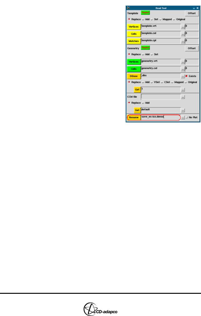
•In the Read Tool, click the ellipsis (...) button next to the Resume file box and select the dense model file (save_es-ice.dense) from the file browser. This action loads the model and displays the dense mesh in the Template window.
The meshing pipeline in es-ice generates the 2D and 3D templates, trims and assembles the mesh, and executes the Star Setup process. Entering the following es-ice command will run the meshing pipeline and rebuild the mesh with the latest version of the code:
Pipeline, TrimmedModel, StopAt, StarControlsLoad
As the pipeline re-runs Star Setup, you must reload the model into Star Controls, redefine the interface between manifolds and ports and redefine the boundary patches. For convenience, the Star Controls panel settings are already correctly defined. If you are unfamiliar with these settings or the Star Controls panel, please consult Chapter 6 of this volume.
To redefine the model in Star Controls:
•In the Select panel, click Star Controls
•In the Load model view of the Star Controls panel, click Load Model
•In the Assembly view of the Star Controls panel, redefine the interface between the manifolds and ports as follows:
•In the Plot Tool, deselect the Fill toggle button and click CPlot
•In the Star Controls panel, select the Partial toggle button and click CP
Match
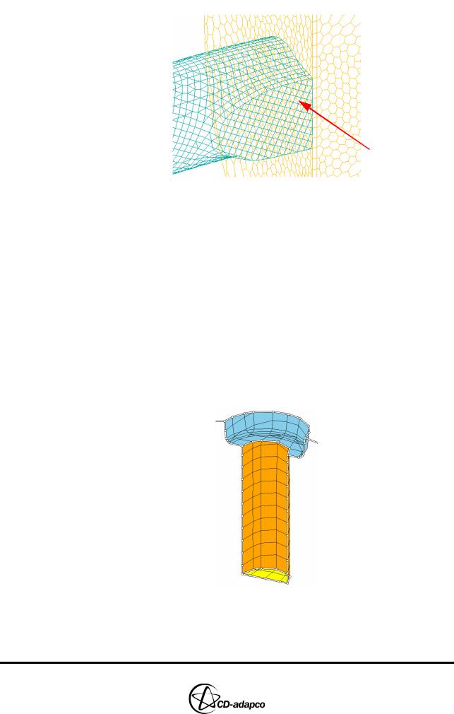
•In the Controls Workspace window, click an interior face between the intake manifold and port, as shown in Figure 13-3
Version 4.20 |
13-3 |
![](/html/2706/288/html_WQoyFmCctM.Y0DJ/htmlconvd-2zW8VV164x1.jpg)
MESH REPLACEMENT |
Chapter 13 |
Rebuilding the Dense Mesh |
|
|
|
Interior Face
Figure 13-3 Interior face between intake port and manifold
•In the Star Controls panel, deselect the Partial toggle button and click
CP Match
•In the Controls Workspace window, click an interior face between the exhaust manifold and port
•Click CPTransform
•Click Finish
•In the Boundary Conditions view of the Star Controls panel, redefine the boundary patches as follows:
•For the Cylinder domain, under Extra Regions > Spark Plug, click Define
•In the Plot Tool, select the Fill toggle button
•In the Boundary Tool, click Display All
•Click Keep Picked and select the patches that define the spark plug in the Controls Workspace, as shown in Figure 13-4
Figure 13-4 Spark Plug patches
•In the Boundary Tool, click Define
•For the Port and Valve 1 domain, under Extra Regions > Intake Flow
13-4 |
Version 4.20 |
![](/html/2706/288/html_WQoyFmCctM.Y0DJ/htmlconvd-2zW8VV165x1.jpg)
Chapter 13 |
MESH REPLACEMENT |
|
Rebuilding the Dense Mesh |
|
|
Boundary, click Define
•In the Boundary Tool, click Display All
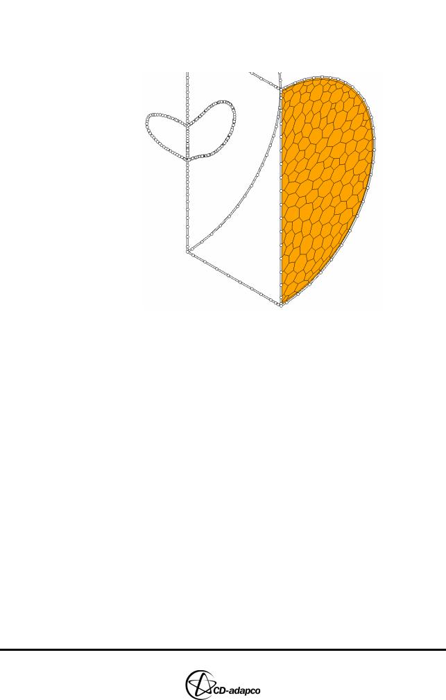
•Click Keep Picked and select the patches that define the intake flow boundary in the Controls Workspace, as shown in Figure 13-5
Figure 13-5 Intake flow boundary
•In the Boundary Tool, click Define
•For the Port and Valve 2 domain, under Extra Regions > Exhaust Flow Boundary, click Define
•In the Boundary Tool, click Display All
•Click Keep Picked and select the patches that define the exhaust flow boundary in the Controls Workspace, as shown in Figure 13-6
Version 4.20 |
13-5 |