

USING THE AUTOMATIC 2D TEMPLATE |
Chapter 10 |
Adding Features to the Automatic 2D Template |
|
|
|
You can check that the refinement covers the fuel injector by displaying the template on top of the geometry:
•In the Plot Tool, activate the Geometry window from the drop-down menu
•Enter the following command to collect all geometry shells into the current CSet:
CSet, All
•Deselect the Mesh toggle button to remove the mesh lines from the display
•In the Plot Tool, activate the General Workspace window from the drop-down menu
•Deselect the Fill toggle button to display only the mesh lines
•Click DPlot to display the automatic 2D template on top of the geometry
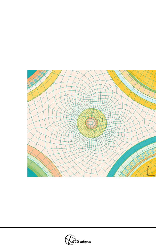
•Zoom in on the region around the injector as shown in Figure 10-10
Figure 10-10 Mesh refinement around the fuel injector
Adding Features to the Automatic 2D Template
Another ability of the automatic 2D template is to capture mesh features using line cells. Such cells are generated when preparing the original geometry surface in STAR-CCM+.
To include line cells as features, you must add them to the geometry CSet 4. If you do not have line cells in your geometry, you can use splines instead but these must be added to the geometry SSet 4.
10-10 |
Version 4.20 |
Chapter 10 |
USING THE AUTOMATIC 2D TEMPLATE |
|
Adding Features to the Automatic 2D Template |
|
|
es-ice is capable of filtering out unnecessary features and only including those that are required for a good quality 2D template.
•In the Plot Tool, activate the Geometry window from the drop-down menu.
•Enter the following command to isolate and display all line cells:
CSet, Newset, Line CPlot
•Enter the following command to save the line cells in CSet 4, the cell set representing features of the automatic 2D template:
CSet, Save, 4
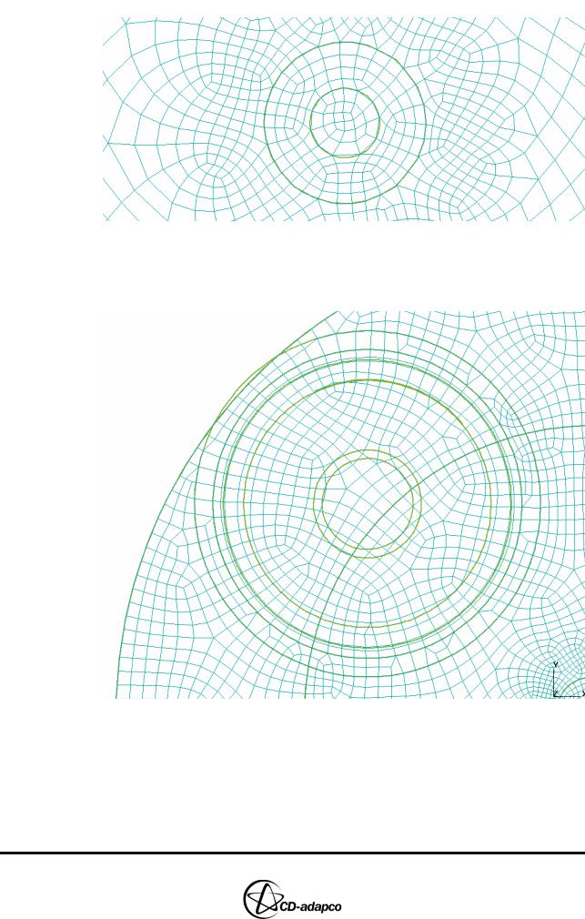
Figure 10-11 shows the set of line cells.
Figure 10-11 Line cells for features in the 2D template
Next, recreate the automatic 2D template which this time will include the above features:
•In the Automatic 2D parameters panel, click Create 2D
•In the Plot Tool, click DPlot to view the 2D template on top of the line cells
Figure 10-12 shows that mesh lines in the 2D template follow the fuel injector features.
Version 4.20 |
10-11 |
USING THE AUTOMATIC 2D TEMPLATE |
Chapter 10 |
Using Detailed Automatic 2D Template Parameters |
|
|
|
Figure 10-12 Mesh lines on fuel injector
Figure 10-13 shows that mesh lines in the 2D template also follow features on the valve recess and piston bowl.
Figure 10-13 Mesh lines on valve recess
Using Detailed Automatic 2D Template Parameters
A number of parameters are available for the automatic 2D template that give greater control over the template generation process. For more information on these controls see Table 4-9 in the User Guide.
To use detailed control parameters for the automatic 2D template:
10-12 |
Version 4.20 |
Chapter 10 |
USING THE AUTOMATIC 2D TEMPLATE |
|
Using Detailed Automatic 2D Template Parameters |
|
|
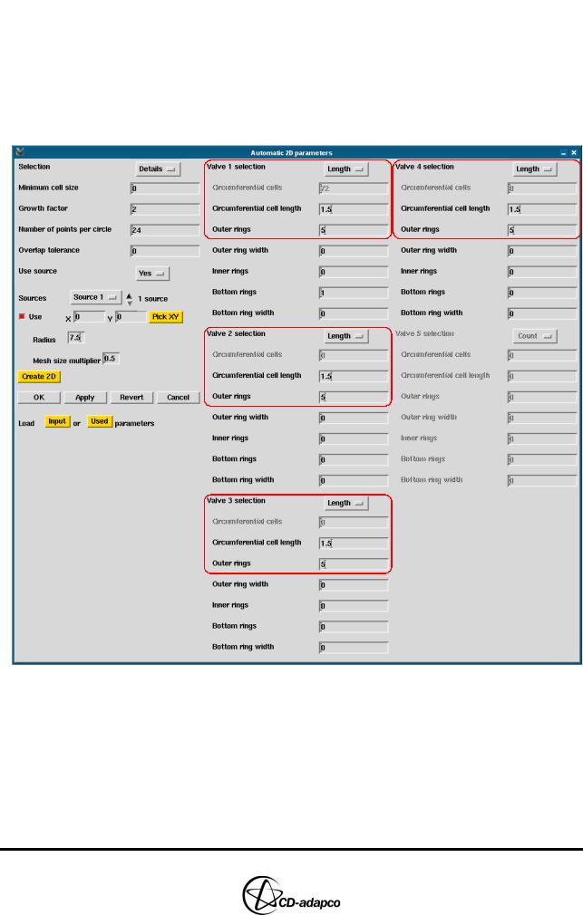
•In the Automatic 2D parameters panel, set Selection to Details
•Set Valve 1 selection to Length
•Set Circumferential cell length to 1.5
•Set Outer rings to 5
•Repeat the above settings for Valve 2, Valve 3 and Valve 4 as shown in Figure 10-14
•Click Create 2D
Figure 10-14 Detailed parameters for automatic 2D templates
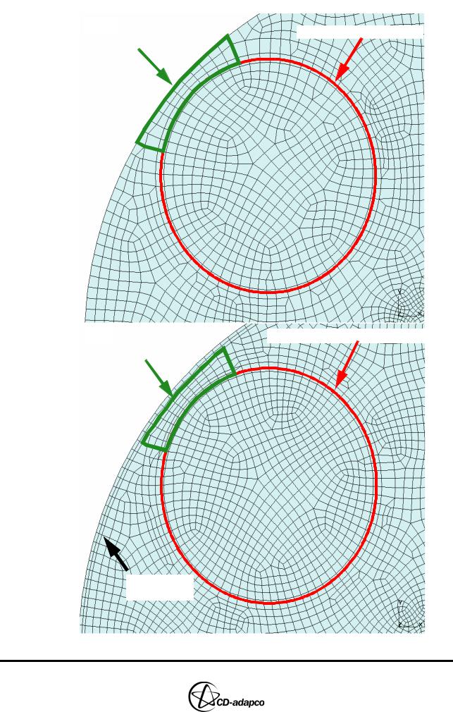
Figure 10-15 shows the template before and after the application of these controls.
Version 4.20 |
10-13 |
USING THE AUTOMATIC 2D TEMPLATE |
Chapter 10 |
Using Detailed Automatic 2D Template Parameters |
|
|
|
Before |
Circumferential Cells = 72 |
|
Outer Ring |
||
|
After |
Circumferential Cell Length = 1.5 |
Outer Ring |
|
Extra rings for valve overhang
Figure 10-15 Mesh comparison before and after using detailed parameters
10-14 |
Version 4.20 |