

Chapter 4 |
MESHING WITH THE TRIMMING METHOD |
|
Assembling the Trimmed Template |
|
|
cases some vertices will be missing from Template VSet 10.
•To add any missing vertices, select Sets > VSet > Add > Cursor (equivalent to command VSet, Add, Cursor) from the menu bar
•To remove vertices, select Sets >VSet > Delete > Cursor (equivalent to command VSet, Delete, Cursor) from the menu bar
•Once the correct vertices are in the current vertex set, save them into Template VSet 10 (labelled Cylinder wall vertices) by clicking T: cylinder verts 10 in the training panel
Improving cell connectivity
The trimmed template often contains short edges whose vertices are difficult to smooth using the es-ice built-in smoother algorithm. These difficulties arise because short edges result in polyhedral cells with many cell faces.
To collapse small edges or to reduce the number of polyhedral cell faces:
•In the Trim panel, select the Cylinder part from the drop-down menu and click Get
•Select Edges from the drop-down menu and
enter 0.05 in the adjacent box
• Click VMerge to collapse edges whose length is less than or equal to 0.05
•Click Put to put the updated trimmed template back into the trimming database
•Repeat the previous steps for the ports and valves
Assembling the Trimmed Template
In a previous section you defined a flow boundary on the Intake and Exhaust ports. This creates a patch on the flow boundary regions of both ports (see Figure 4-31). These patches project the wall cell layers onto the flow boundaries.
Intake
Figure 4-31 Creating a patch on inlet boundary faces
Version 4.20 |
4-25 |

MESHING WITH THE TRIMMING METHOD |
Chapter 4 |
Assembling the Trimmed Template |
|
|
|
You can now assemble the mesh parts and add a prismatic cell layer to the wall boundaries.
•In the Trim panel, set Extrusion to 0.4 to add a prismatic layer of 0.4 mm to the full model
•Click Assemble to combine the mesh parts
Figure 4-32 shows the completed trimmed template.
Figure 4-32 Assembled model
Figure 4-33 is a section plot of the assembled model showing the cell layers on the wall and flow boundaries
|
|
|
|
Wall boundary |
Flow boundary |
||
cell layer |
cell layer |
||
Figure 4-33 Section plot of the complete assembly with a full extrusion layer
4-26 |
Version 4.20 |
Chapter 4 |
MESHING WITH THE TRIMMING METHOD |
|
Running Star Setup |
|
|
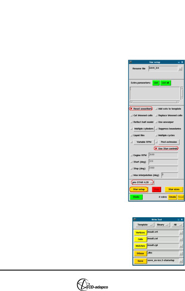
Running Star Setup
The final stage of the trimming method is to run Star Setup. This process generates the make_ev.tab file, which details the cell layer addition and deletion events for the cylinder and valves. It also creates and stores the save_ice_after_map file as an image within the model file.
You can add command-line options by clicking the List button above the scroll list box and then looking up the command in the Help panel. It is necessary to separate these options with a space, or by entering them on separate lines.
To run Star Setup:
•In the Select panel, click Star Setup
•In the Star Setup panel, activate the Reset smoothers toggle button
•Deactivate the Use unwarper toggle button
•Check that the Use Star controls toggle button is selected
•Select pro-STAR 4.20 from the pro-STAR pull-down menu
•Click Star setup
Saving the Model
•In the Write Tool, enter save_es-ice.3-starsetup and click
Save
Version 4.20 |
4-27 |