

Chapter 15 |
DIESEL ENGINE: FULL-CYLINDER CLOSED-CYCLE MODEL |
|
Generating the Closed-Cycle Polyhedral Mesh |
|
|
Generating the Closed-Cycle Polyhedral Mesh
In this section, you will generate a closed-cycle polyhedral mesh that includes a spray-optimised zone. The mesh represents the engine as a 3D discretised volume suitable for a fuel spray and combustion analysis.
The steps needed to generate the mesh are as follows:
1.Assign surface shells to geometry cell sets
2.Specify the General, Events and Cylinder parameters
3.Create a spray-optimised mesh zone to improve fuel injection modelling
4.Import a user intermediate surface to separate the upper and lower portions of the polyhedral mesh and thus facilitate the addition and deletion of cell layers
5.Check that the spray-optimised zone is suitable for the supplied engine geometry and user intermediate surface
6.Create the closed-cycle polyhedral mesh
Assigning shells to geometry cell sets
The first stage of the meshing process is to assign surface shells to a number of special geometry cell sets. The es-ice mesher uses these sets to define the essential engine cylinder components. Shells are assigned to geometry cell sets using either the training panel or es-ice commands (if you are familiar with them).
•In the menu bar, select Panels > Directory
•In the Main es-ice window, enter the directory of the training user panel
•In the menu bar, select Panels > training to open the training panel
To define the geometry cell sets:
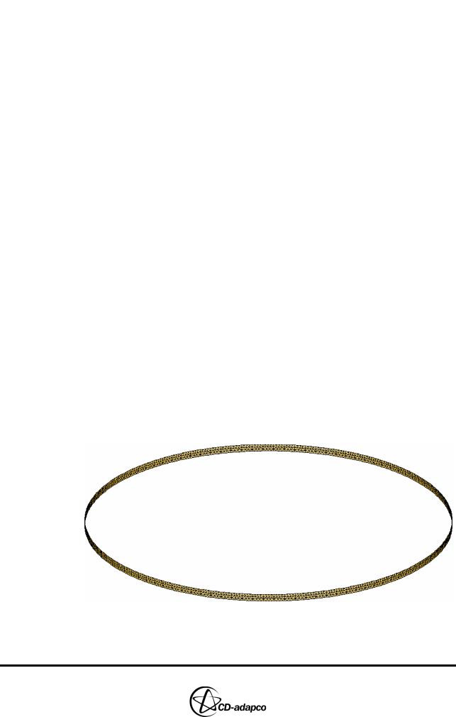
•Enter the following command to isolate the cylinder shells shown in Figure 15-2:
CSet, Newset, Name, Liner
•In the training panel, click Cylinder Shells to save cylinder wall shells into
CSet 1
Figure 15-2 Cylinder shell selection
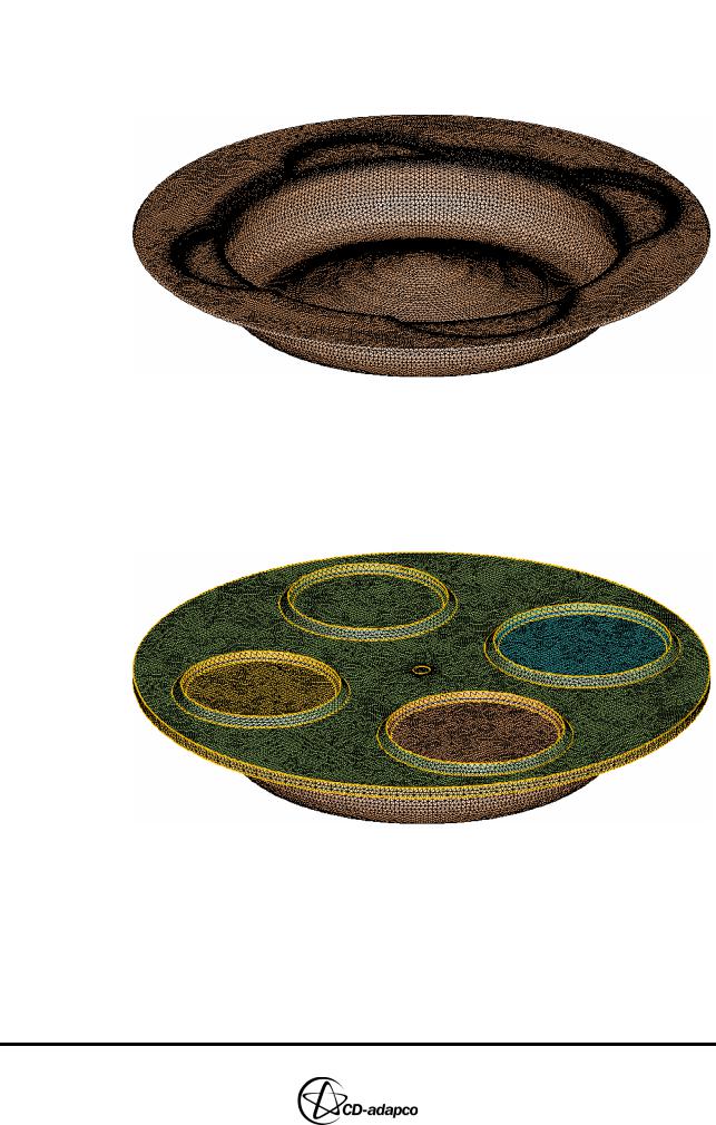
•Enter the following command to isolate the piston shells shown in Figure
Version 4.20 |
15-3 |
DIESEL ENGINE: FULL-CYLINDER CLOSED-CYCLE MODEL |
Chapter 15 |
Generating the Closed-Cycle Polyhedral Mesh |
|
|
|
15-3
CSet, Newset, Name, Piston
•In the training panel, click Piston Shells
Figure 15-3 Piston shells
•Enter the following commands to isolate the trimming shells shown in Figure 15-4
CSet, All
•In the training panel, click Trimming Shells
Figure 15-4 Trimming shells
Specifying General, Events and Cylinder parameters
Next, set the General, Events and Cylinder parameters that define various engine characteristics and operating conditions.
•In the Select panel, click Create Template
•In the Create Template panel, select Closed cycle from the drop-down menu at the top of the panel, as shown in Figure 15-5.
15-4 |
Version 4.20 |
Chapter 15 |
DIESEL ENGINE: FULL-CYLINDER CLOSED-CYCLE MODEL |
|
Generating the Closed-Cycle Polyhedral Mesh |
|
|
Figure 15-5 Closed-cycle Create Template panel
•Click General
•In the General parameters panel (see Figure 15-6), set the Engine type drop-down menu to Diesel
•Set the Cylinder radius to 65
•Click Ok to accept these settings and close the panel
Figure 15-6 Closed-cycle General parameters panel
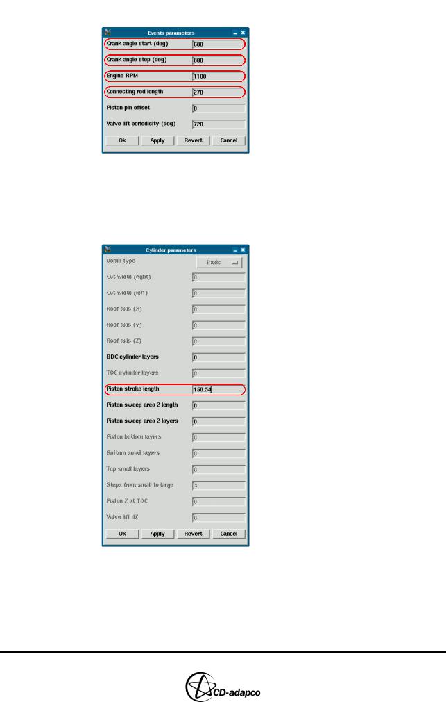
•In the Create Template panel, click Events
•In the Events parameters panel (see Figure 15-7), set Crank angle start (deg) to 680 to specify the beginning of the analysis (i.e. the point at which the intake valves close)
•Set Crank angle stop (deg) to 800 to specify the end of the analysis (i.e. the point at which the exhaust valves open)
•Set Engine RPM to 1100
•Set Connecting rod length to 270
Version 4.20 |
15-5 |
DIESEL ENGINE: FULL-CYLINDER CLOSED-CYCLE MODEL |
Chapter 15 |
Generating the Closed-Cycle Polyhedral Mesh |
|
|
|
•Click Ok to accept these settings and close the panel
Figure 15-7 Closed-cycle Events parameters panel
•In the Create Template panel, click Cylinder
•In the Cylinder parameters panel (see Figure 15-8), set the Piston stroke length to 158.54
•Click Ok to accept these settings and close the panel
Figure 15-8 Closed-cycle Cylinder parameters panel
Creating a spray-optimised mesh zone
To define the spray-optimised zone, you must first create eight coordinate systems that define the location and direction of the spray zones. These systems correspond to the fuel injector nozzles. Note that if you intend to use an axisymmetric spray
15-6 |
Version 4.20 |
Chapter 15 |
DIESEL ENGINE: FULL-CYLINDER CLOSED-CYCLE MODEL |
|
Generating the Closed-Cycle Polyhedral Mesh |
|
|
type in your own cases, you do not need to specify these coordinate systems.
•Enter the following commands to define the coordinate systems.
Local, 11, Cylindrical, 1.5, 0, -1.2, Local, 2, Y, 103, Z, 0
RP8, 1, , , 45, , , , , , , 45
•In the Plot Tool, select the Workspace window from the drop-down menu as this window is where the spray zones are displayed
•Select the Local toggle button to display the local coordinate systems
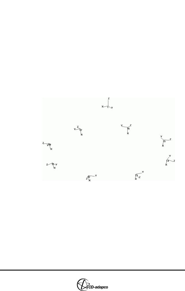
•Enter the following command to zoom out and show all coordinate systems
Zoom, MinMax, -2, 2, -2, 0, Plot
The Workspace window will display the coordinate systems shown in Figure 15-9. The origin of each system defines the centre of the interface between the spray cone and the recess; the z-axis defines the direction of each spray zone (see Chapter 6, “Spray zones” in the User Guide for a definition and illustration of spray zone components).
Figure 15-9 Local coordinate system display
Next, specify the Spray zone parameters defining the dimensions and cell sizes of the spray zone (see Chapter 6, “Spray zone parameters” in the User Guide for definitions and illustrations of the spray zone parameters).
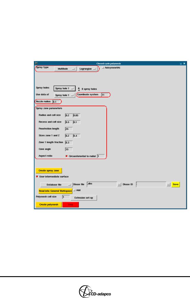
•In the Create Template panel, click Make polymesh
•In the Closed cycle polymesh panel shown in Figure 15-10, ensure that Spray type is set to Multihole and Lagrangian. These settings specify one spray zone per injection point and also that the droplets are defined as Lagrangian parcels (see Chapter 6, “Spray injection mode” in the User Guide)
•Set Coordinate system to 11 to assign the first local coordinate system to the first spray hole
•Set Nozzle radius to 0.1 to specify the diameter of the refinement region around the injector nozzle
•Set Radius and cell size to 0.2 and 0.05 to define the radius at the start of the
Version 4.20 |
15-7 |
DIESEL ENGINE: FULL-CYLINDER CLOSED-CYCLE MODEL |
Chapter 15 |
Generating the Closed-Cycle Polyhedral Mesh |
|
|
|
spray cone and recess, and also the cell size in the radial direction
•Set Recess and cell size to 0.5 and 0.1 to define the length and cell size in the recess axial direction
•Set Penetration length to 25 to specify the extent of the spray cone
•Set Sizes zone 1 and 2 to 0.2 and 0.4 to specify the cell sizes in zones 1 and 2, respectively.
•Set Zone 1 length fraction to 0.3 to specify the length of zone 1
•Set Cone angle to 15 to specify the angle of the spray cone
•Set Aspect ratio to 1 to specify the cell aspect ratio that es-ice aims to maintain throughout the spray zone
Figure 15-10 Closed cycle polymesh panel: Spray zone parameters
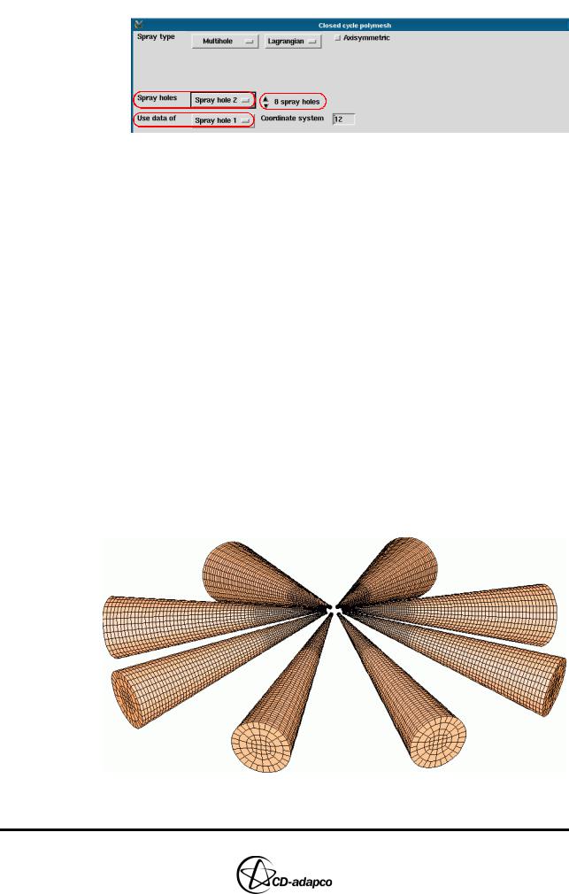
The remaining spray holes are identical to the first, except for the fact that they are defined in terms of different coordinate systems. You can therefore take advantage of the Use data of menu to apply the same spray zone parameters to all spray holes.
•Increase the number of spray holes to 8 spray holes via the up/down scroll arrows and select Spray hole 2 from the drop-down menu
•Check that Use data of is set to Spray hole 1, as shown in Figure 15-11
•Set the Coordinate system to 12
15-8 |
Version 4.20 |
Chapter 15 |
DIESEL ENGINE: FULL-CYLINDER CLOSED-CYCLE MODEL |
|
Generating the Closed-Cycle Polyhedral Mesh |
|
|
Figure 15-11 Use data of drop-down menu
•Repeat the previous steps so that each subsequent spray hole will also use these parameters, and that each coordinate system is assigned as shown in Table 15-2:
Table 15-2: Spray hole coordinate system assignment
Spray Hole |
Coordinate System |
|
|
Spray hole 3 |
Coordinate system 13 |
|
|
Spray hole 4 |
Coordinate system 14 |
|
|
Spray hole 5 |
Coordinate system 15 |
|
|
Spray hole 6 |
Coordinate system 16 |
|
|
Spray hole 7 |
Coordinate system 17 |
|
|
Spray hole 8 |
Coordinate system 18 |
|
|
Finally, create the complete spray zone configuration.
•In the Closed cycle polymesh panel, click Create spray zone
•In the Plot Tool, deselect the Local toggle and click the Off button to display all spray zones in the Workspace panel, as shown in Figure 15-12.
Figure 15-12 Spray zone display
Version 4.20 |
15-9 |