

Chapter 5 |
CREATING AND CHECKING THE MESH |
Chapter 5 CREATING AND CHECKING THE MESH
The model at the beginning of this chapter can be resumed from file:
save_es-ice.3-starsetup
So far, no complete mesh displayed in an es-ice window has been suitable for use by STAR for flow calculations. To check an actual computational mesh, you must first create it and then display it in the Workspace window.
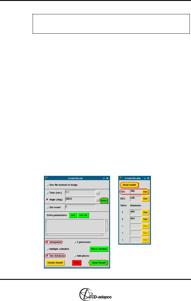
It is recommended that you create and check meshes corresponding to various key crank angles before investing CPU time in a STAR CFD analysis. Typically, the key angles considered are the starting crank angle, TDC, BDC and the crank angles producing maximum valve lifts. In this chapter, you will use the Create Results > Select panel to identify these angles and create the corresponding mesh.
To create and check the computational mesh:
•In the Select panel, click Create Result
•In the Create Result panel (see Figure 5-1), select the Interpolate toggle button to interpolate vertex locations, as opposed to those created by the internal es-ice smoothing algorithms
•Ensure that the Use database toggle button is selected to write the mesh to a
.dbs file
•Click Select
•In the Create Results > Select panel, click Read model to read the key crank angles into the panel
•Click Use next to TDC to create the computational mesh at TDC
•When the Child process is complete, click Read Result to import the resulting mesh into the Workspace window
•Note that a result.d360.0.dbs file is created in the working directory. This file contains the mesh at the specified crank angle
Figure 5-1 Create Results and Create Results > Read panels
Version 4.20 |
5-1 |
CREATING AND CHECKING THE MESH |
Chapter 5 |
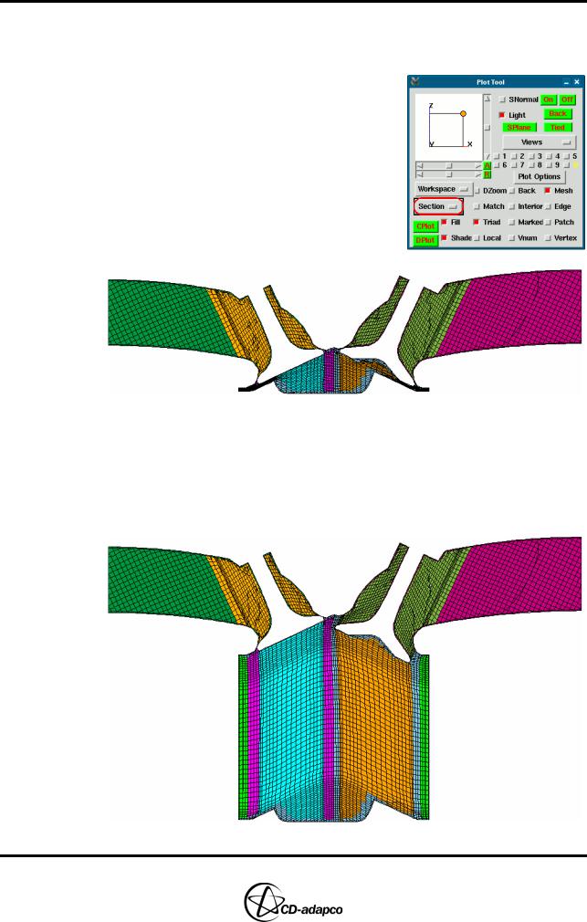
•Enter the following command to check for cells with negative volumes:
Check, NegVolume
•In the Plot Tool, select Section from the plot type drop-down menu
•Enter the following commands to set up a suitable view, as shown in Figure 5-2:
SPoint, 0, 19.5, 0 SNormal, 0, 1, 0 View, 0, -1, 0 CPlot
Figure 5-2 Computational mesh at TDC for a trimmed mesh
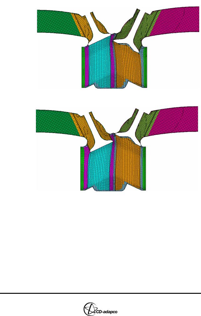
•Follow a similar procedure to create, read and check results at BDC (see Figure 5-3), Valve 1 maximum lift (see Figure 5-4) and Valve 2 maximum lift (see Figure 5-5). Note that some lines running through the mesh are not actual mesh lines but rather the result of plotting a section that cuts through cells at some awkward places.
Figure 5-3 Computational mesh at BDC for a trimmed mesh
5-2 |
Version 4.20 |
Chapter 5 |
CREATING AND CHECKING THE MESH |
|
|
Figure 5-4 Computational mesh at maximum Valve 1 lift for a trimmed mesh
Figure 5-5 Computational mesh at maximum Valve 2 lift for a trimmed mesh
Version 4.20 |
5-3 |