


Chapter 4 |
MESHING WITH THE TRIMMING METHOD |
|
Creating the 3D Template |
|
|
Creating the 3D Template
Now that the 2D template has been created, you can adjust the remaining parameters in the third template dimension using the Create Template panel. Note that, in general, a value of “0” in the parameter boxes means that es-ice will calculate a default value. It is recommended that you initially use as many parameter defaults as possible.
By looking at the Valve 1 lift file (vlift01.dat), you can see that the maximum valve lift is close to 9.4 millimetres. The aim of this tutorial is to achieve a cell spacing of 1 millimetre at maximum valve lift. This consideration will therefore determine some of the settings you will apply to the model in the following steps (see Chapter 4, “The Valve parameters panel” in the User Guide for more information on valve parameters). Note that when modeling valves using the trimming method many of these parameters are not required.
To define the valve parameters:
•In the Create Template panel, select Valve 1 from the Valves drop-down menu
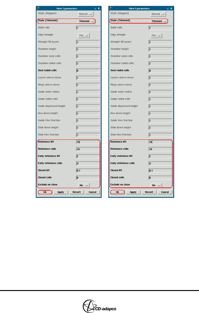
•In the Valve 1 parameters panel (see Figure 4-25), ensure Style (Trimmed) is set to Trimmed
•Set Reference lift to 10
•Set Reference cells to 10
•es-ice aims to maintain the vertical cell spacing in the valve curtain equal to the Reference lift divided by the Reference cells. Therefore, the above parameters will give a cell spacing of approximately 1 millimetre
•Ensure that Early reference lift is set to 2
•Ensure that Early reference cells is set to 4
•These parameters result in a finer mesh for low valve lifts, as es-ice aims to create four cells when the valve is open by 2 millimetres. This setting gives a cell spacing of approximately 0.5 millimetres at low valve lift.
•Ensure that Closed lift is set to 0.1
•This parameter is the valve lift at which the STAR solver considers the valve as closed, which will then avoid a large pressure difference across a small area.
•In addition, this distance allows room for two extrusion layers (on the valve face and on the valve seat) and one Closed cell layer when the valve is closed. You will apply a full extrusion layer at a later stage.
•Ensure Exclude on close is set to No
•Accept the remaining default values and click Ok
•Repeat these settings for Valve 2, as shown in Figure 4-25
Version 4.20 |
4-19 |
MESHING WITH THE TRIMMING METHOD |
Chapter 4 |
Creating the 3D Template |
|
|
|
Figure 4-25 3D parameters for Valves 1 and 2 (see also Figure 4-25 in the User Guide)
The final stage in creating the 3D template is to define the Cylinder and Trim parameters. As part of this process, you will set the Piston DZ parameter to move the piston automatically by a specified amount before trimming. Recall that the piston is currently at the TDC position, but template trimming requires you to move the piston down a few millimetres. This increased clearance allows enough space for the mesher to add several deletion layers between the dome and the piston. If the piston does not move by the specified amount, it is probably because you have not set Geometry CSet 2 correctly.
To set the Cylinder and Trim parameters:
•In the Create Template panel, click Cylinder
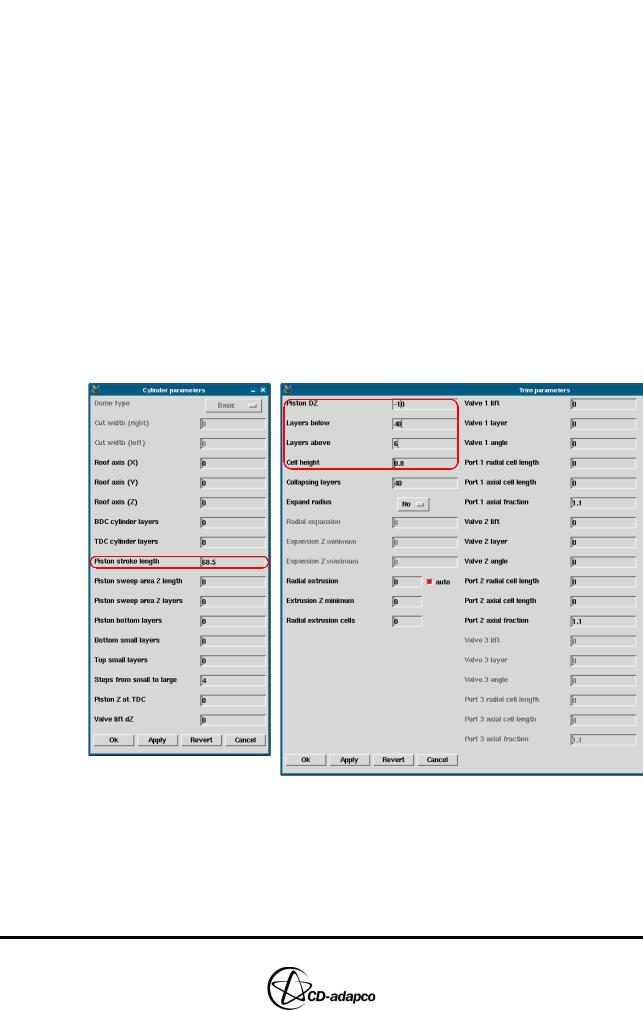
•In the Cylinder parameters panel (see Figure 4-26), set the Piston stroke length to 68.5
4-20 |
Version 4.20 |
Chapter 4 |
MESHING WITH THE TRIMMING METHOD |
|
Creating the 3D Template |
|
|
•Accept the remaining default parameters and click Ok
•In the Create Template panel (see Figure 4-26), click Trim
•In the Trim parameters panel set Piston DZ to -10; this is a good starting value for most cases
•Set Layers below to 40
•Set Layers above to 6
•Adjust these parameters so that the generated 3D template covers the piston, the dome and the valve seat. An example of the result of this adjustment is shown in Figure 4-29.
•Note that entering large parameter values guarantees that the template covers the geometry. However, this practice is not recommended because it increases the size of the es-ice model file.
•Set Cell height to 0.8
•This setting ensures that the template cell layers are created with a height of approximately 1 millimetre. This is very close to the cell height in the valve curtain, as previously defined.
•Accept the remaining default parameters and click Ok
Figure 4-26 Modified cylinder and trim parameters
Figure 4-27 shows that the piston has moved down by 10 millimetres.
Version 4.20 |
4-21 |
MESHING WITH THE TRIMMING METHOD |
Chapter 4 |
Creating the 3D Template |
|
|
|
Figure 4-27 Piston moved down by 10 mm (Piston DZ parameter - Trim Parameters panel)
After all parameters have been set:
•In the Create Template panel, click Make Template to create the template and write its data to a file with default name save_ice
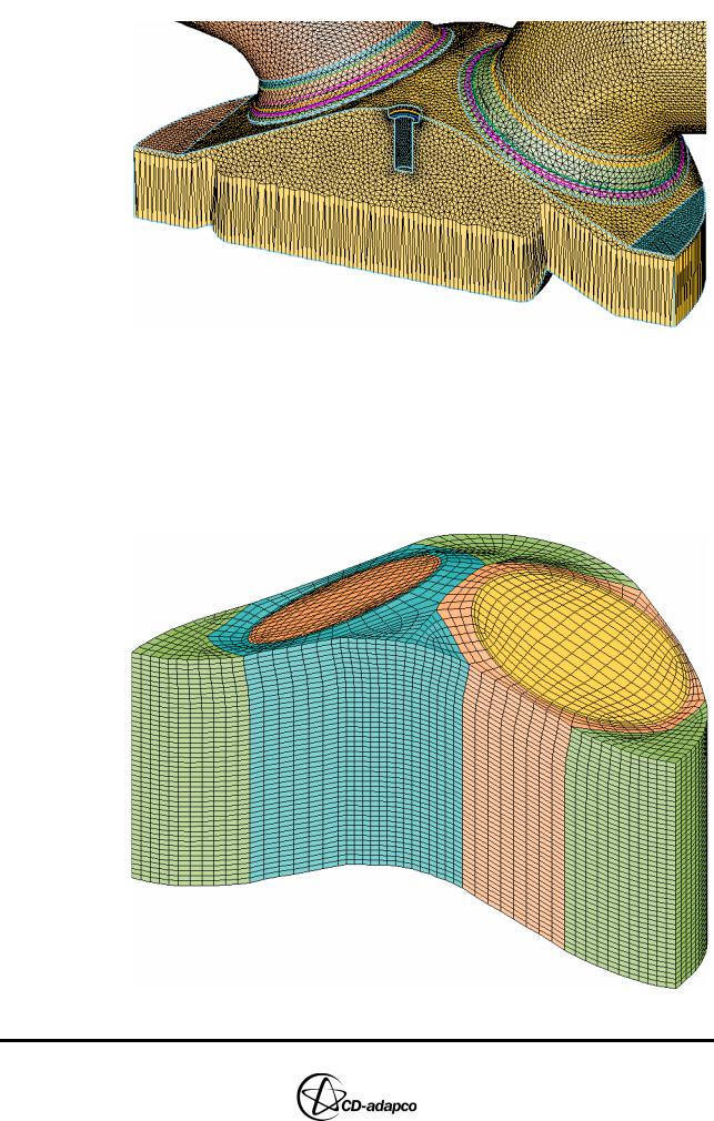
•Click Read Template to read the 3D template into the current working session and plot it in the Template window, as shown in Figure 4-28
Figure 4-28 Template window: 3D template for trimming
4-22 |
Version 4.20 |
Chapter 4 |
MESHING WITH THE TRIMMING METHOD |
|
Creating the 3D Template |
|
|
Note that new local coordinate systems are created for the valves (with coordinate system IDs 13 and 14). These systems are repositioned to the bottom of the closed valves and rotated to θ = 0.
Finally, create a double-plot of the template over the geometry surface to check that enough cell layers are included to generate a trimmed template.
•In the Plot Tool, select Geometry from the drop-down menu to activate the
Geometry window
•Collect all geometry cells into the current cell set
•Deselect the Mesh toggle button
•Select Template from the drop-down menu to activate the Template window
•Deselect the Fill toggle button
•Set Views to 0, -1, 0
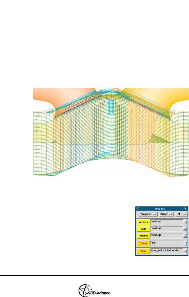
•Click DPlot to display the template on top of the geometry surface, as shown in Figure 4-29.
Figure 4-29 Template window: Overlay of template and geometry
It is recommended that you save your work up to this point by writing the current model data into a new save_es-ice file.
•In the Write Tool, enter save_es-ice.2-beforetrim and click
Save
Version 4.20 |
4-23 |