


SDF Annotator Guide
Using the Configuration File
MODULE Keyword
The MODULE keyword maps path delays and timing checks from the SDF file to Verilog HDL description, performs scaling operations for a specific type of module, and selects min:typ:max delay data.
The syntax for the MODULE keyword is as follows:
MODULE module_name
{
[MTM = [MINIMUM | TYPICAL | MAXIMUM];] [SCALE_FACTORS = min_mult:typ_mult:max_mult;] [MAP_INNER = path;
(original_timing) = [ADD | OVERRIDE | IGNORE] [{(new_timing);}]
]
}
The following table describes the arguments to the MODULE keyword.
Argument |
Description |
|
|
module_name |
Name of a specific type of module (not instance name) |
|
specified in the corresponding Verilog HDL description. |
MTM |
Specifies the minimum, typical, or maximum delays from the |
|
SDF file. See “MTM Keyword” on page 21 for more |
|
information. |
SCALE_FACTORS |
See “SCALE_FACTORS Keyword” on page 21 for more |
|
information. |
[MAP_INNER] |
See “MAP_INNER Keyword” on page 24 for more information. |
(Optional) |
|
|
|
Note: The MTM and SCALE_FACTORS arguments to the MODULE keyword affect only the IOPATH, DEVICE, and TIMINGCHECK information annotated to the specified module_name module; they do not affect scale factors specified for other modules in the same design.
MAP_INNER Keyword
The MAP_INNER keyword is an optional argument to the MODULE keyword. It specifies a subsequent module in the hierarchy of the module specified with the MODULE keyword. You can specify the MAP_INNER keyword for each subsequent module in the module hierarchy.
January 2001 |
24 |
Product Version 3.2 |

SDF Annotator Guide
Using the Configuration File
The syntax for the MAP_INNER keyword is as follows:
MAP_INNER = path;
(original_timing) = [ADD | OVERRIDE | IGNORE] { (new_timing); }
The following table describes the arguments to the MAP_INNER keyword.
Argument |
Description |
|
|
path |
Verilog HDL hierarchical path of a submodule within |
|
module_type of the MODULE keyword. The paths specified |
|
in the SDF file are mapped to module_type. This path |
|
applies to all path delays and timing checks specified for this |
|
module in the SDF file including those mapped with ADD and |
|
OVERRIDE. |
original_timing |
The path delay or timing specification that is in the SDF file. |
new_timing |
The path delay in the Verilog description that corresponds to the |
|
original_timing delay. |
ADD |
Adds to the mapping specifications of the SDF file. The |
|
original_timing specification is mapped to |
|
new_timing, the Verilog HDL syntax of a path delay or timing |
|
check. |
OVERRIDE |
Replaces the mapping specifications of the SDF file. The |
|
original_timing specification is mapped to |
|
new_timing, the Verilog HDL syntax of a path delay or timing |
|
check. |
IGNORE |
Ignores the mapping specifications in the SDF file. |
|
|
Note: In all cases, the path name is applied to all new_timing specifications before they are annotated to the Verilog family tool.
Examples of Using the MODULE and MAP_INNER Keywords
The following examples shows how the MODULE and MAP_INNER keywords work.
Example 1
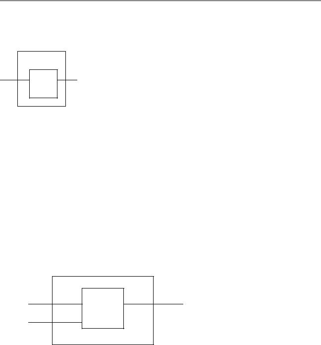
This example applies module mapping to the shift module type, which contains a submodule called m2 and specifies that the delay between in1 and out1 in the SDF file is
January 2001 |
25 |
Product Version 3.2 |
SDF Annotator Guide
Using the Configuration File
to be mapped to the delay between i and x of m2 in Verilog, using minimum delays and a scaling factor of 2.0.
shift |
|
in1 i m2 |
x out1 |
MODULE shift
{
MTM = MINIMUM; SCALE_FACTORS = 2.0:2.0:2.0; MAP_INNER = m2;
(in1 => out1) = OVERRIDE
{
(i => x)
}
}
Example 2
In this example, two mappings are performed with the MAP_INNER keyword. Using the
OVERRIDE keyword with the hierarchical design in the following figure, this example shows how to map and annotate the delay from the path ctrl_in1=>ctrl_out1 to the path moto_i=>moto_o, and clk=>moto_o.
ctrl_module
|
moto_ctrl |
ctrl_in1 moto_i |
moto_o ctrl_out1 |
CLK clk
The Verilog design has a specify block with the following path delay specification:
(moto_i => moto_o) = (3, 4);
The SDF file for the design has the following delay specification for the path:
(IOPATH ctrl_in1 ctrl_out1 (5) (6))
January 2001 |
26 |
Product Version 3.2 |

SDF Annotator Guide
Using the Configuration File
A module mapping for this hierarchy is specified in the SDF configuration file as follows:
MODULE ctrl_module
{MAP_INNER = moto_ctrl;
(ctrl_in1 => ctrl_out1) = OVERRIDE { (moto_i => moto_o);
(clk => moto_o); }
}
Example 3
Using the IGNORE keyword with the same hierarchy as shown in
Example 2, the following mapping in the configuration file ignores the specification in the SDF
file and continues to use the timing in the Verilog design.
MODULE ctrl_module
{ MAP_INNER = moto_ctrl;
(ctrl_in1 => ctrl_out1) = IGNORE; }
Example 4
In this example three mappings are done using the MAP_INNER keyword. Using the ADD keyword with the hierarchy in the following figure, this example shows how to map a path from
(clk=>moto_o2) and
(clk=>moto_o1) in addition to the (CLK=>OUT) mapping.
|
|
|
|
ctrl_module |
|
|
OUT |
|||
|
|
|
|
|
|
|
|
|||
ctrl_in1 |
moto_i1 |
|
|
|
|
|
|
|||
|
|
|
|
|
moto_ctrl |
moto_o1 |
|
ctrl_out1 |
||
ctrl_in2 |
moto_i2 |
|
||||||||
|
|
|||||||||
|
|
|
|
|
|
|||||
|
moto_o2 |
|
ctrl_out2 |
|||||||
|
|
|
CLK |
clk |
|
|
||||
|
|
|
|
|
|
|
|
|
||
|
|
|
|
|
|
|
|
|
|
|
|
|
|
|
|
|
|
|
|
|
|
The following mapping example allows the annotation of the delay specified for the IOPATH (CLK =>OUT) to (CLK =>OUT), (clk=>moto_o1) and (clk=>moto_o2).
MODULE ctrl_module
{ MAP_INNER = moto_ctrl; (CLK => OUT) = ADD
{(clk => moto_o1); (clk => moto_o2); }
}
Example 5
This examples shows how to specify IOPATH mappings with a COND condition around them.
For example, if the Verilog design has a specify block with the following conditional statement:
January 2001 |
27 |
Product Version 3.2 |

SDF Annotator Guide
Using the Configuration File
specify
if (TI_cond0)
(A => B) = (3:4:5); endspecify
And the SDF file for the design has a statement for annotation:
(COND TI_cond0
(IOPATH A B(0.2:0.3:0.4) (0.27:0.37:0.47)))
The configuration file for mapping can have a specification:
IF (TI_cond0)
(A => B) = OVERRIDE { (a => b); }
The conditions in the SDF file are compared to the condition in the configuration file and mapping is performed if the conditions match.
Rules for Module Mapping with Conditional Delays
The rules for module mapping in the case of conditional path delays are shown in the following tables. Table 2-4 on page 28 shows different combinations of how Verilog design path delays are handled in the SDF annotation process, when combined with the COND statements of SDF. Table 2-5 on page 28 shows the rules for mapping paths between the SDF file and the configuration file.
Table 2-4 Annotating Path Delays in Verilog-XL
SDF |
Verilog-XL |
Annotate action |
|
|
|
no condition |
no condition |
Annotate one path |
no condition |
conditional path |
Annotate to all conditions in the design, unless an |
|
delay |
ifnone is present |
COND |
no_cond |
No annotation |
COND |
conditional path |
Annotate one path |
|
delay |
|
|
|
|
Table 2-5 Module Mapping in SDF
SDF File |
Config File |
Map action |
|
|
|
no condition |
no condition |
Mapping performed |
no condition |
COND |
No mapping performed |
January 2001 |
28 |
Product Version 3.2 |
|
SDF Annotator Guide |
|
|
Using the Configuration File |
|
|
|
|
Table 2-5 |
Module Mapping in SDF |
|
|
|
|
SDF File |
Config File |
Map action |
|
|
|
COND |
no condition |
Mapping performed |
COND |
COND |
Mapping performed |
|
|
|
January 2001 |
29 |
Product Version 3.2 |