

SDF Annotator Guide
Using the SDF File
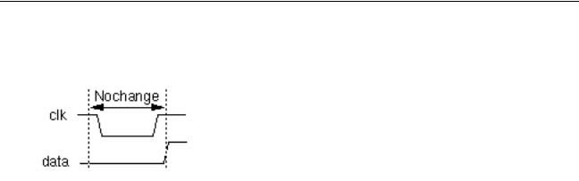
(NOCHANGE (negedge clk) data (4.5) (4.5))
)
TIMINGENV Keyword and Constructs
The TIMINGENV keyword and its constructs are ignored by Verilog-XL and Verifault-XL. However, the following syntax is included for completeness. Specifying the TIMINGENV keyword constructs will not generate an error message. The TIMINGENV keyword associates constraint values with critical paths in the design and provides information about the timing environment in which the circuit operates. The syntax is as follows:
(TIMINGENV
{(PATHCONSTRAINT {"path_name"} start_path {int_path+} end_path max_rise max_fall)}
{(PERIODCONSTRAINT edge_clk max_period {(EXCEPTION (INSTANCE path+))} {(SKEWCONSTRAINT port_path max_skew)}
{(SUM (start_path end_path) {(start_path end_path)+} (start_end_sum) {(start_end_sum)+})}
{(DIFF (start_path end_path) {(start_path end_path)+} (start_end_diff) {(start_end_diff)+})}
{(ARRIVAL {(edge port)} port_name early_rise late_rise early_fall late_fall)} {(DEPARTURE {(edge port)} port_name early_rise late_rise early_fall late_fall)}
{(SLACK port rise_setup fall_setup rise_hold fall_hold {clk_period} ) {(WAVEFORM port wave_period (edge num1 {num2}) + (edge num1 {num2})+ )
)
Constraint entries provide information about the timing properties that a design is required to have to meet certain design objectives. A tool that is synthesizing some aspect of the design
(logic synthesis, layout, and so on) will.
PATHCONSTRAINT Keyword
The PATHCONSTRAINT keyword specifies the maximum allowable delay for a path, which is typically identified by the two ports at each end of the path. Path constraints are the critical paths in a design identified during timing analysis. You can also specify intermediate ports to
January 2001 |
72 |
Product Version 3.2 |

SDF Annotator Guide
Using the SDF File
uniquely identify path(s). Layout tools use these constraints to direct the physical design. The syntax is as follows:
(PATHCONSTRAINT {"path_name"} start_path {int_path+} end_path max_rise max_fall)
The following table describes the arguments of the PATHCONSTRAINT keyword.
Keyword |
Description |
|
Argument |
||
|
||
|
|
|
path_name |
Optional symbolic or actual name of the path. |
|
start_path |
Start of port path. Where applicable, a port path can have array index |
|
|
(for example, x.y[3].p). |
|
int_path |
Intermediate points to describe the path. You can have multiple |
|
|
int_path arguments. Where applicable, a port path can have array |
|
|
index (for example, x.y[3].p). |
|
end_path |
End of port path. Where applicable, a port path can have array index |
|
|
(for example, x.y[3].p). |
|
max_rise |
Maximum rise delay between the start and end path points. |
|
max_fall |
Maximum fall delay between the start and end path points. |
|
|
|
The following example shows how to use the PATHCONSTRAINT keyword:
(INSTANCE x)
(TIMINGENV (PATHCONSTRAINT y.z.i3 y.z.o2 a.b.o1 (25.1) (15.6)))
|
|
|
|
|
|
|
|
|
|
|
|
|
x |
|
|
|
|
|
|
|
|
|
|
|
|
|
|
||
|
|
|
|
|
|
y |
|
|
|
|
|
|
a |
|
|
|
|
i1 |
z |
|
|
|
|
|
|
|
|||
|
|
|
|
|
o1 |
|
|
|
|
i1 b |
|
|
|
|
|
|
|
i2 |
|
|
|
|
|
|
|
|
|
||
|
|
|
|
|
|
|
||||||||
|
|
|
|
|
o2 |
|
|
|
|
|
|
o1 |
|
|
|
|
|
i3 |
|
|
|
|
i2 |
|
|
||||
|
|
|
|
|
|
|
|
|
|
|
|
|
||
|
|
|
|
|
|
|
|
|
|
|
|
|
||
|
|
|
|
|
|
|
|
|
|
|
|
|
|
|
|
|
|
|
|
|
|
|
|
|
|
|
|
|
|
|
|
|
|
|
|
|
|
|
|
|
|
|
|
|
|
|
|
|
|
|
|
|
|
|
|
|
|
|
|
|
|
|
|
|
|
|
|
|
|
|
|
|
|
|
The following example shows a cell entry specifying a path constraint.
(CELL (CELLTYPE “DFF”) (INSTANCE a.b.c) (TIMINGCHECK
January 2001 |
73 |
Product Version 3.2 |

SDF Annotator Guide
Using the SDF File
(PATHCONSTRAINT y.z.i3 a.b.o1 (25)(15))
)
)
PERIODCONSTRAINT Keyword
The PERIODCONSTRAINT keyword specifies the maximum time allowable for one complete cycle of the signal. The syntax is as follow:
(PERIODCONSTRAINT edge_clk max_period {(EXCEPTION (INSTANCE path+))})
The following table describes the arguments of the PERIODCONSTRAINT keyword.
Keyword Argument |
Description |
|
|
edge_clk |
Edge-triggered clock event. |
max_period |
Maximum period for complete signal cycle. |
EXCEPTION |
A list of one or more cell instances to be excluded from the |
|
group. |
INSTANCE |
Cell instance. |
|
|
Note: You must specify the PERIODCONSTRAINT keyword at a code-hierarchy level that includes the cell instance that drives the common clock inputs of the flip-flops and any cell instances to be placed in the exception list.
The following example shows how to use the PERIODCONSTRAINT keyword.
(INSTANCE x) (TIMINGENV
(PERIODCONSTRAINT bufa.y (10) (EXCEPTION (INSTANCE dff3))
)
SKEWCONSTRAINT Keyword
The SKEWCONSTRAINT keyword specifies the clock event signal which is constrained against the associated port signals. For example, in a chain of devices such as counters that are connected to the same clock signal, the clock ideally changes at exactly the same time at all counters. However, there is some delay between the change at one device and the change at another. If this delay exceeds the signal skew limit, the data passed along the chain is unreliable. The syntax is as follows:
(SKEWCONSTRAINT port_path max_skew)
January 2001 |
74 |
Product Version 3.2 |
SDF Annotator Guide
Using the SDF File
The following table describes the arguments of the SKEWCONSTRAINT keyword.
Keyword |
Description |
|
Argument |
||
|
||
|
|
|
port_path |
Port that drives the net. Where applicable, a port path can have array |
|
|
index (for example, x.y[3].p). |
|
max_skew |
Maximum skew between signals is identified as a design constraint by |
|
|
timing analysis tools. This information can be passed through the SDF |
|
|
file to layout tools to ensure that the physical design is laid out within |
|
|
these constraints. |
|
|
|
The following example shows how to use the SKEWCONSTRAINT keyword:
(INSTANCE z)
(TIMINGENV (SKEWCONSTRAINT (posedge i2) (7.5)))
z
|
|
i1 x |
|
|
|
i1 |
y |
|
|
|
|
|
|
||||
|
|
i2 |
|
|
i2 |
|
||
|
|
|
|
|
|
|||
|
|
|
|
|
|
|
|
|
|
|
|
|
|
|
|
|
|
SUM Keyword
The SUM keyword specifies the maximum sum of two or more path delays. The syntax is as follows:
(SUM (start_path end_path) {(start_path end_path)+} (start_end_sum) {(start_end_sum)+}
)
The following table describes the arguments of the SUM keyword.
Keyword Argument |
Description |
|
|
start_path |
Start of port path. Where applicable, a port path can have array |
|
index (for example, x.y[3].p). |
end_path |
End of port path. Where applicable, a port path can have array |
|
index (for example, x.y[3].p). |
January 2001 |
75 |
Product Version 3.2 |

SDF Annotator Guide
Using the SDF File
Keyword Argument |
Description |
start_end_sum Sum of the individual delays associated with each start and end port pair. The sum of all port pair delays must be less than the value of start_end_path.
Note: You can specify additional paths by using additional pairs of start_path and end_path arguments with corresponding start_end_sum arguments.
The following example shows how to use the SUM keyword:
(INSTANCE x) (TIMINGENV
(SUM (m.n.o1 y.z.i1) (y.z.o2 a.b.i2) (67.3))
)
|
|
|
|
|
|
|
|
|
|
|
|
|
|
|
|
|
|
x |
|
|
|
|
|
m |
|
|
|
|
|
|
|
|
|
|
|
|
|
|
|
|
|
n |
|
|
|
|
|
y |
|
|
|
|
|
a |
|
|
|
|
|
|
|
|
|
|
|
|
|
|
|
|
|||||
|
i1 |
|
|
|
o1 |
|
|
i1 |
z |
|
|
|
|
|
|
|
||
|
|
|
|
|
|
|
|
|
|
|
|
|
||||||
|
|
|
|
|
|
|
|
|
|
o1 |
|
|
|
b |
|
|
|
|
|
|
|
|
|
|
|
|
|
|
|
|
|
|
|
|
|||
|
i2 |
|
|
|
|
|
|
i2 |
|
|
|
|
i1 |
|
|
|
||
|
|
|
|
|
|
|
|
o2 |
|
|
|
|
o1 |
|
||||
|
|
|
|
|
|
|
|
|
|
|
|
|
||||||
|
|
|
|
|
|
|
|
|
|
|
|
|
|
|
|
|||
|
|
|
|
|
|
|
|
|
|
|
|
|
|
|
|
|||
|
|
|
|
|
|
|
|
|
|
|
|
|
|
|
|
|||
|
|
|
|
|
|
|
|
|
i3 |
|
|
|
|
|
i2 |
|
|
|
|
|
|
|
|
|
|
|
|
|
|
|
|
|
|
|
|
||
|
|
|
|
|
|
|
|
|
|
|
|
|
|
|
|
|
||
|
|
|
|
|
|
|
|
|
|
|
|
|
|
|
|
|
|
|
|
|
|
|
|
|
|
|
|
|
|
|
|
|
|
|
|
|
|
|
|
|
|
|
|
|
|
|
|
|
|
|
|
|
|
|
|
|
|
|
|
|
|
|
|
|
|
|
|
|
|
|
|
|
|
|
|
|
|
|
|
|
|
|
|
|
|
|
|
|
|
|
|
|
|
|
|
|
|
|
|
|
|
|
|
|
|
|
|
|
|
|
|
|
|
DIFF Keyword
The DIFF keyword specifies the maximum allowable difference between the delays of two paths in a design. The syntax is as follows:
(DIFF (start_path end_path) {(start_path end_path)+} (start_end_diff) {(start_end_diff)+}
)
The following table describes the arguments of the DIFF keyword.
Keyword Argument |
Description |
|
|
start_path |
Start of port path. Where applicable, a port path can have array |
|
index (for example, x.y[3].p). |
end_path |
End of port path. Where applicable, a port path can have array |
|
index (for example, x.y[3].p). |
January 2001 |
76 |
Product Version 3.2 |
SDF Annotator Guide
Using the SDF File
Keyword Argument |
Description |
start_end_diff Maximum difference between two path delays. The difference of the individual delays in the two circuit paths must be less than the value of start_end_diff.
Note: You can specify additional paths by using additional pairs of start_path and end_path arguments with corresponding start_end_diff arguments.
The following example shows how to use the DIFF keyword:
(INSTANCE x) (TIMINGCHECK
(DIFF (m.n.o1 y.z.i1) (y.z.o2 a.b.i2) (8.3))
)
ARRIVAL Keyword
The ARRIVAL keyword specifies the time when a primary input signal is applied during the intended circuit operation. You use this keyword to analyze the timing behavior for a circuit and to compute logic constraints for logic synthesis and layout. The syntax is as follows:
(ARRIVAL {(edge port)} port_name early_rise late_rise early_fall late_fall)
The following table describes the arguments of the ARRIVAL keyword.
Keyword Argument |
Description |
|
|
edge |
Either posedge or negedge. |
port |
The input port from which the time reference is specified. This is |
|
the required primary input signal is a fan-out from a sequential |
|
element (usually an active edge of a clock signal). |
port_name |
The input or inout port for which the arrival time is to be defined. |
|
This port must be a primary (external) input of the top-level |
|
module. |
early_rise |
Earliest rise value relative to the time reference. This value must |
|
be less than the late_rise value. |
late_rise |
Latest rise value relative to the time reference. This value must |
|
be greater than the early_rise value. |
early_fall |
Earliest fall value relative to the time reference. This value must |
|
be less than the late_fall value. |
January 2001 |
77 |
Product Version 3.2 |

|
SDF Annotator Guide |
|
|
Using the SDF File |
|
|
|
|
|
|
|
Keyword Argument |
Description |
|
|
|
|
late_fall |
Latest fall value relative to the time reference. This value must be |
|
|
greater than the early_fall value. |
|
|
|
|
The following example shows how to use the ARRIVAL keyword. It applies rising transitions at D[15:0] no sooner than 10 and no later than 40 time units after the rising edge of the reference time MCLK. It applies falling transitions no sooner than 12 and no later than 45 time units after the edge.
(INSTANCE top) (TIMINGENV
(ARRIVAL (posedge MCLK) D[15:0] (10) (40) (12) (45))
)
DEPARTURE Keyword
The DEPARTURE keyword specifies the time when a primary output signal is applied during the intended circuit operation. You use this keyword to analyze the timing behavior for a circuit and to compute logic constraints for logic synthesis and layout. The syntax is as follows:
(DEPARTURE {(edge port)} port_name early_rise late_rise early_fall late_fall)
The following table describes the arguments of the DEPARTURE keyword.
Keyword Argument |
Description |
|
|
edge |
Either posedge or negedge. |
port |
The input port from which the time reference is specified. This |
|
is the required primary input signal is a fan-out from a |
|
sequential element (usually an active edge of a clock signal). |
port_name |
The output or inout port for which the departure time is to be |
|
defined. This port must be a primary (external) output of the |
|
top-level module. |
early_rise |
Earliest rise value relative to the time reference. This value |
|
must be less than the late_rise value. |
late_rise |
Latest rise value relative to the time reference. This value must |
|
be greater than the early_rise value. |
early_fall |
Earliest fall value relative to the time reference. This value must |
|
be less than the late_fall value. |
January 2001 |
78 |
Product Version 3.2 |

|
SDF Annotator Guide |
|
Using the SDF File |
|
|
|
|
Keyword Argument |
Description |
|
|
late_fall |
Latest fall value relative to the time reference. This value must |
|
be greater than the early_fall value. |
|
|
The following example shows how to use the DEPARTURE keyword. It applies rising transitions at A[15:0] no sooner than 8 and no later than 20 time units after the rising edge of the reference time SCLK. It applies falling transitions no sooner than 12 and no later than
34 time units after the edge.
(INSTANCE top) (TIMINGENV
(DEPARTURE (posedge SCLK) D[15:0] (8) (20) (12) (34))
)
SLACK Keyword
The SLACK keyword compares the calculated delay over a path to the delay constraints imposed upon the path and determines the available slack or margin in the delay path. Positive slack indicates that the constraints are met with additional time units to spare.
Negative slack indicates a failure to construct a circuit according to the constraints. The syntax is as follows:
(SLACK port rise_setup fall_setup rise_hold fall_hold {clk_period})
The following table describes the arguments of the SLACK keyword.
Keyword Argument |
Description |
|
|
port |
Input port that provides the slack or margin information. |
rise_setup |
Additional rise delay that can be tolerated in all paths ending at |
|
the port without causing the design constraint to be violated. |
fall_setup |
Additional fall delay that can be tolerated in all paths ending at |
|
the port without causing the design constraint to be violated. |
rise_hold |
Reduction of rise delay that can be tolerated in all paths ending |
|
at the port without causing the design constraint to be violated. |
fall_hold |
Reduction of fall delay that can be tolerated in all paths ending at |
|
the port without causing the design constraint to be violated. |
clk_period |
Optionally represents the clock period on which the slack or |
|
margin values are based. The clock period is specified by the |
|
WAVEFORM keyword construct. |
|
|
January 2001 |
79 |
Product Version 3.2 |

SDF Annotator Guide
Using the SDF File
Note: You can specify multiple SLACK keyword constructs for the same port and are distinct as long as the value of clk_period is different.
The following example shows that the signal arrives at port macro.AOI6.B in time to meet the setup time requirement of a flip-flop down the path with 3 time units to spare. Therefore, the delay of any and all paths leading to port macro.AOI6.B can be increased by an additional 3 time units without violating a setup requirement. The example also shows that the delay of any data paths leading to port macro.AOI6.B can be decreased by 7 time units without violating a hold requirement.
(CELL
(CELLTYPE "cpu" (INSTANCE macro.AOI6) (TIMINGENV
(SLACK B (3) (3) (7) (7))
)
)
WAVEFORM Keyword
The WAVEFORM keyword specifies a periodic waveform that is applied to a circuit during its intended operation. Typically, you use this to define a clock signal. You use this keyword to analyze the timing behavior for a circuit and to compute logic constraints for logic synthesis and layout. The syntaxes are as follows:
(WAVEFORM port wave_period (posedge num1 {num2}) (negedge num1 {num2}) )
(WAVEFORM port wave_period (negedge num1 {num2}) (posedge num1 {num2}) )
Note: Specifying posedge or negedge first determines the direction of the transition.
The following table describes the arguments of the WAVEFORM keyword.
Keyword |
Description |
|
Argument |
||
|
||
|
|
|
port |
Input or inout port where the waveform will appear. |
|
wave_period |
Number that specifies the waveform which repeats indefinitely at the |
|
|
interval. |
|
num1 |
When specified alone, defines the transition offset. |
|
|
When specified with num2, defines the beginning of the uncertainty |
|
|
region in which the transition takes place. |
January 2001 |
80 |
Product Version 3.2 |
SDF Annotator Guide
Using the SDF File
Keyword |
Description |
|
Argument |
||
|
||
num2 |
Defines the end of the uncertainty region in which the transition takes |
|
|
place. |
If the port is not a primary input of the circuit, (if it is driven by the output of some other circuit element in the scope of the analysis), then the signal driven in the circuit should be ignored and the specified waveform should replace it in the analysis.
The following example shows the specification of a waveform of period 15 to be applied to port top.clka. Within each period, a rising edge occurs at somewhere between 0 and 2 and a falling edge somewhere between 5 and 7.
(CELL |
(CELLTYPE "cpu") |
|
(INSTANCE top) |
|
(TIMINGENV (WAVEFORM clka 15 (posedge 0 2) (negedge 5 7)) |
) |
) |
|
The following example shows the specification of a waveform of period 25 to be applied to port top.clkb. Within each period, a falling edge occurs at 0, a rising edge at 5, a falling edge at 10, and a rising edge at 15.
(CELL (CELLTYPE "cpu") (INSTANCE top)
(TIMINGENV (WAVEFORM clkb 25 (negedge 0) (posedge 5) (negedge 10) (posedge 15))
)
)
The following example shows negative numbers in defining a waveform.
(CELL (CELLTYPE "cpu") (INSTANCE top)
(TIMINGENV (WAVEFORM clkb 50 (negedge -10) (posedge 20))
)
)
January 2001 |
81 |
Product Version 3.2 |