


SDF Annotator Guide
Using the SDF File
DELAY Keyword and Constructs
The DELAY keyword specifies the delay values associated with module paths, nets, interconnects, devices, and ports. You can specify the keyword entries listed in the following syntax.
(DELAY |
|
|
|
{(ABSOLUTE |
|
|
|
(IOPATH port_spec port_path delay_list) |
|
|
|
(COND cond_port_expr |
|
|
|
(IOPATH port_spec |
port_path |
|
|
{(RETAIN delay_list)} delay_list) |
) |
|
|
(CONDELSE |
|
|
|
(IOPATH port_spec |
port_path |
|
|
{(RETAIN delay_list)} delay_list) |
) |
|
|
(PORT port_path delay_list) |
|
|
|
(INTERCONNECT port_path1 port_path2 delay_list |
) |
||
(NETDELAY name delay_list) |
|
|
|
(DEVICE {port_path} delay_list))} |
|
|
|
{(INCREMENT |
|
|
|
(IOPATH port_spec port_path rdelay_list) |
|
|
|
(COND cond_port_expr |
|
|
|
(IOPATH port_spec port_path |
|
|
|
{(RETAIN rdelay_list)} rdelay_list) |
) |
|
|
(CONDELSE |
|
|
|
(IOPATH port_spec |
port_path |
|
|
{(RETAIN rdelay_list)} rdelay_list) |
) |
|
|
(PORT port_path rdelay_list) |
|
|
|
(INTERCONNECT port_path1 port_path2 rdelay_list) |
|
||
(NETDELAY name rdelay_list) |
|
|
|
(DEVICE {port_instance} rdelay_list))} |
|
|
|
{(PATHPULSE port_path1 {port_path2} (reject) {(error)})}
{(PATHPULSEPERCENT port_path1 {port_path2} (reject) {(error)} )}
)
Note: The delay_list variable in the syntax descriptions of this guide can be specified as any of the syntaxes for delays shown in the following table. Also, a delay can be a single value or three values representing minimum, typical, and maximum delays in the form min:typ:max. Although you can specify up to 12 delays, Verilog-XL and Verifault-XL use only the first six.
Transitions |
Delay Syntax |
|
|
All transitions |
delay |
Rise and fall |
(delay, delay) |
Rise, fall, and Z |
(delay, delay, delay) |
01, 10, 0Z, Z1, 1Z, Z0 |
(delay, delay, delay, |
|
delay, delay, delay) |
January 2001 |
43 |
Product Version 3.2 |

SDF Annotator Guide
Using the SDF File
Transitions |
Delay Syntax |
|
|
|
|
01, 10, 0Z, Z1, 1Z, Z0, |
(delay, delay, delay, |
|
0X, X1, 1X, X0, XZ, ZX |
delay, delay, delay, |
|
|
delay, |
delay, delay, |
|
delay, |
delay, delay) |
|
|
|
ABSOLUTE Keyword
The ABSOLUTE keyword specifies the delay values that replace the existing delay values in the design. The syntax for the ABSOLUTE keyword construct is as follows:
(ABSOLUTE |
|
|
(IOPATH port_spec port_path delay_list) |
|
|
(COND cond_port_expr |
|
|
(IOPATH port_spec |
port_path |
|
{(RETAIN delay_list)} delay_list)) |
|
|
(CONDELSE |
|
|
(IOPATH port_spec |
port_path |
|
{(RETAIN delay_list)} delay_list)) |
|
|
(PORT port_path delay_list) |
|
|
(INTERCONNECT port_path1 port_path2 delay_list |
) |
|
(NETDELAY name delay_list) |
|
|
(DEVICE {port_path} delay_list) |
|
|
) |
|
|
In the following example, the delay values in the examples are specified as two min:typ:max triplets. The first triplet is the delay for a rising edge transition and the second triplet is the delay for a falling edge transition.
(CELL
(CELLTYPE "DFF") (INSTANCE a.b.c) (DELAY
(ABSOLUTE
(IOPATH (posedge clk) q (22:28:33) (25:30:37)) (PORT clr (32:39:49) (35:41:47))
)
)
)
INCREMENT Keyword
The INCREMENT keyword specifies delay values that are positive or negative and that are added to the existing delay values. The syntax for the INCREMENT keyword construct is as follows:
(INCREMENT
(IOPATH port_spec port_path rdelay_list)
(COND cond_port_expr |
|
(IOPATH port_spec |
port_path |
January 2001 |
44 |
Product Version 3.2 |

|
SDF Annotator Guide |
|
|
Using the SDF File |
|
|
|
|
{(RETAIN rdelay_list)} rdelay_list) |
) |
|
(CONDELSE |
|
|
(IOPATH port_spec |
port_path |
|
{(RETAIN rdelay_list)} rdelay_list) |
) |
|
(PORT port_path rdelay_list) |
|
|
(INTERCONNECT port_instance1 port_instance2 rdelay_list) (NETDELAY name rdelay_list)
(DEVICE {port_instance} rdelay_list)
)
Note: You can only use positive numbers (delay_list) with the ABSOLUTE keyword; you can use positive or negative numbers (rdelay_list) with the INCREMENT keyword. Other than this difference, the keywords have the same syntax. The following sections describe the constructs that you can use within the ABSOLUTE and INCREMENT keyword constructs.
In the following example, the delay values in the examples are specified as two min:typ:max triplets. The first triplet is the delay for a rising edge transition and the second triplet is the delay for a falling edge transition.
(CELL (CELLTYPE "DFF") (INSTANCE a.b.c) (DELAY (INCREMENT
(IOPATH (posedge clk) q (-4::2) (-7::5)) (PORT clr (2:3:4) (5:6:7))
)
)
)
IOPATH Keyword
The IOPATH keyword specifies delays on a path from an input port to an output port of a device and optional reject limits and error limits on the path. The syntax for the IOPATH keyword is as follows:
(IOPATH port_spec port_path {(RETAIN rdelay_list)} rdelay_list)
The following table describes the arguments of theIOPATH keyword
Keyword Argument |
Description |
|
|
port_spec |
Input or inout (bidirectional) port. An edge identifier can be |
|
included. |
port_path |
Output or inout port. Where applicable, a port path can have an |
|
array index. For example: x.y[3].p. |
RETAIN |
Ignored by Verilog-XL and Verifault-XL because retain delays are |
|
not supported by these tools. It is part of the syntax only for |
|
completeness. |
January 2001 |
45 |
Product Version 3.2 |
SDF Annotator Guide
Using the SDF File
Keyword Argument |
Description |
|
|
rdelay_list |
IOPATH delay from port_spec to port_path. The delay can |
|
also include optional reject and error limit specifications. You can |
|
specify negative numbers only within the INCREMENT keyword |
|
construct. |
|
|
Each delay value is associated with a unique input port/output port pair.
Note: The SDF Annotator calculates the reject and error limit values as follows to determine the level of acceptance for a delay value on a module path.
error_limit = (error%/100) * (module_path_delay) reject_limit = (reject%/100) * (module_path_delay)
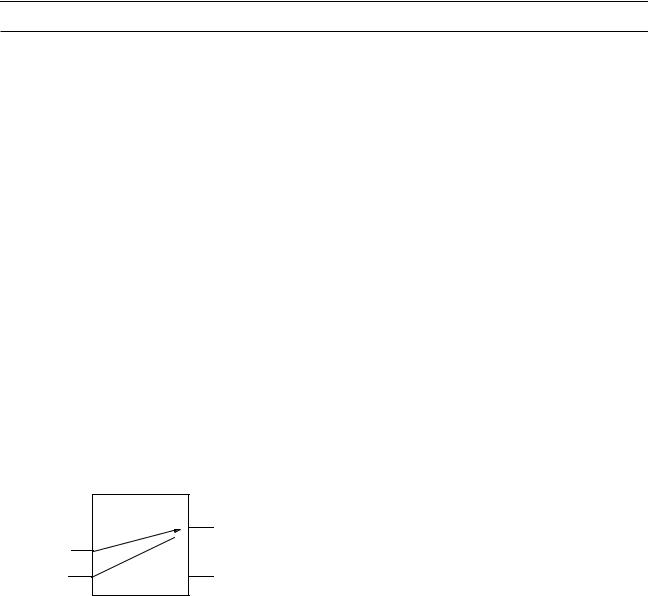
In the following example, the delay_list for each IOPATH is a set of three min:typ:max triplets that specifies the delays for rise, fall, and turn-off transitions. This example also includes a conditional IOPATH using the COND construct to represent statedependent path delays.
(INSTANCE x.y.z) (DELAY (ABSOLUTE
(IOPATH (posedge i1) o1 (2:3:4) (4:5:6) (3:5:6)) (IOPATH i2 o1 (2:4:5) (5:6:7) (4:6:7))
(COND i1 (IOPATH i3 o1 (2:4:5) (4:5:6) (4:5:7))
)
)
i1
x.y.z

 o1 i2
o1 i2 
i3
o2
To specify optional reject and error limits, enclose the entire delay_list in parentheses and enclose the delay, reject limit, and error limit in their own parentheses. For example, the following construct specifies one delay. For all transitions, the delay is 12, the reject limit is 6, and the error limit is 10.
(IOPATH A B ((12:12:12) (6:6:6) (10:10:10)))
To specify that a current delay is to be maintained, use an empty set of parentheses. For example, the following IOPATH statement would annotate a delay of 3:5:7 and an error limit of 2:3:6, while keeping the current setting for the reject limit.
(IOPATH A B ((3:5:7) ( ) (2:3:6)))
The following commented examples illustrate the syntax for the IOPATH keyword construct.
January 2001 |
46 |
Product Version 3.2 |

SDF Annotator Guide
Using the SDF File
(IOPATH A B (12:12:12))
//Delay=12 for all transitions
//Reject and error limits are not specified,
//and are set equal to the delay.
(IOPATH A B (12:12:12) (10:10:10))
//Delay=12 for rise transition.
//Delay=10 for fall transition.
//Reject and error limits are not specified,
//and are set equal to the delay.
(IOPATH A B ((12:12:12) (10:10:10)))
//Delay=12 and reject=10 for all transitions.
//Error limit is not included,
//so it is set equal to reject limit.
(IOPATH A B ((12:12:12) (6:6:6) (10:10:10)))
//Delay=12, reject=6, error=10
//for all transitions.
(IOPATH A B ((12:12:12) ( ) (10:10:10))) // Delay=12, reject=current value, //error=10 for all transitions.
(IOPATH A B (12:12:12) ((10:10:10) (5:5:5) (9:9:9)))
//Delay=12, reject=12, error=12
//for rise transition.
//Delay=10, reject=5, error=9
//for fall transition.
(IOPATH A B ((12:12:12) (6:6:6) (8:8:8)) ((10:10:10) (5:5:5) (9:9:9)))
//Delay=12, reject=6, error=8
//for rise transition.
//Delay=10, reject=5, error=9
//for fall transition.
(IOPATH A B ((12:12:12) (6:6:6)) ((10:10:10) (5:5:5) (9:9:9)))
//Delay=12, reject=6, error=6
//for rise transition.
//Delay=10, reject=5, error=9
//for fall transition.
(IOPATH A B ((5:5:5) (2:2:2) (3:3:3)) ((6:6:6) (3:3:3) (4:4:4)) ((15:15:15) (7:7:7) (10)) ((14:14:14) (6:6:6) (9:9:9)) ((12:12:12) (7:7:7) (9:9:9)) ((13:13:13) (5:5:5) (8:8:8)))
//Delay=5, reject=2, error=3 for 01 transition.
//Delay=6, reject=3, error=4 for 10 transition.
//Delay=15, reject=7, error=10 for 0Z transition.
//Delay=14, reject=6, error=9 for Z1 transition.
//Delay=12, reject=7, error=9 for 1Z transition.
//Delay=13, reject=5, error=8 for Z0 transition.
January 2001 |
47 |
Product Version 3.2 |

SDF Annotator Guide
Using the SDF File
COND Keyword
The COND keyword specifies conditional module path delays. The syntax is as follows:
(COND cond_port_expr
(IOPATH port_spec port_path
{(RETAIN rdelay_list)} rdelay_list
)
)
The following table describes the arguments of the COND keyword.
Keyword Argument |
Description |
|
|
cond_port_expr |
Boolean description of the state dependencty of the delay. The |
|
delay values apply only if cond_port_expr is true(logical |
|
one). |
IOPATH |
See IOPATH Keyword on page 45 for more information. |
port_spec |
Input or inout port that can have an edge identifier. |
port_path |
Output or inout port. Where applicable, a port path can have an |
|
array index. For example: x.y[3].p. |
RETAIN |
Ignored by Verilog-XL and Verifault-XL because both these tools |
|
do not support retain delays. It is part of the syntax only for |
|
completeness. |
rdelay_list |
IOPATH delay from port_spec to port_path. |
|
|
CONDELSE Keyword
The CONDELSE keyword specifies path delays when a signal change must be propagates to an output or inout, but none of the conditions for module paths to it are true. The syntax is as follows:
(CONDELSE
(IOPATH port_spec port_path
{(RETAIN rdelay_list)} rdelay_list
)
)
The following table describes the arguments of the CONDELSE keyword.
Keyword Argument |
Description |
|
|
IOPATH |
See IOPATH Keyword on page 45 for more information. |
January 2001 |
48 |
Product Version 3.2 |

SDF Annotator Guide
Using the SDF File
Keyword Argument |
Description |
|
|
port_spec |
Input or inout port that can have an edge identifier. |
port_path |
Output or inout port. Where applicable, a port path can have an |
|
array index. For example: x.y[3].p. |
RETAIN |
Ignored by Verilog-XL and Verifault-XL because both these tools |
|
do not support retain delays. It is part of the syntax only for |
|
completeness. |
rdelay_list |
IOPATH delay from port_spec to port_path. |
|
|
Use the CONDELSE keyword to cover all cases for a path that have not been specified in COND keyword constructs.
RETAIN Keyword
The RETAIN keyword specifies the time for which an output or inout port retains its previous logic value after a change at a related input or inout port. It is specified inside an IOPATH keyword construct. Use the RETAIN keyword on paths that proceed from the address or select inputs to the data outputs of memory and register file circuits. Also, you should use this keyword only where the cell timing model includes an explicit mechanism for providing retention times. The syntax is as follows:
(RETAIN delay_list)
The delay_list variable specifies the retention time data from the port_spec to the port_path variables in the IOPATH keyword construct. Consecutive delays in the delay_list must be increasing numerically.
The following example shows the retain time of the bus do[7:0] with respect to changes on the bus addr[13:0]. The rise time (4:5:7) proceeds from low to X; the fall time
(5:6:9) proceeds from high to X.
(IOPATH addr[13:0] do[7:0] (RETAIN (4:5:7) (5:6:9))
PORT Keyword
The PORT keyword specifies estimated or actual interconnect delay values you can place on the input port, without having to specify a start point for the wire path. The syntax is as follows:
(PORT port_path delay_list)
January 2001 |
49 |
Product Version 3.2 |
SDF Annotator Guide
Using the SDF File
The following table describes the arguments of the PORT keyword.
Keyword Argument |
Description |
|
|
port_path |
Input or inout port. Where applicable, a port path can have an |
|
array index. For example: x.y[3].p. |
delay_list |
PORT delay of the port_path. Optional reject and error limits |
|
can be included. |
|
|
If you specify interconnect delays and port delays for the same input of a module, the SDF
Annotator uses whichever specification appears last in the SDF file.
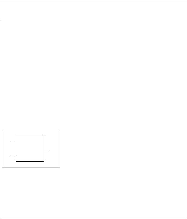
In the following example, the delay consists of one min:typ:max triplet specifying the minimum, typical, and maximum delays for all transitions. The PORT delay is specified as incremental, which means the existing delay data values are increased or decreased rather than replaced.
(INSTANCE x) (DELAY
(INCREMENT (PORT a.b.i1 (-2:0:2)))
)
x
a.b
i1
o1
i2
Port delays are mapped to Module Input Port Delays (MIPDs). By default, MIPDs use inertial delays. Verilog-XL has interconnect transport delay functionality with pulse control, which is enabled by using the +transport_int_delays and the +multisource_int_delays plus options.
Verilog-XL generates Single-source Interconnect Transport Delays (SITDs) or Multi-source Interconnect Transport Delays (MITDs), as shown in the following table:
Plus Option |
Single-source Nets |
Multi-source Nets |
|
|
|
+transport_int_delays |
SITD |
SITD |
January 2001 |
50 |
Product Version 3.2 |
SDF Annotator Guide
Using the SDF File
Plus Option |
Single-source Nets |
Multi-source Nets |
|
|
|
+multisource_int_delays |
MIPD |
MITD |
Both plus options |
SITD |
MITD |
Neither plus option |
MIPD |
MIPD |
|
|
|
For more information and examples of valid and invalid interconnect combinations, see Appendix B, “Valid and Invalid Interconnect Combinations.”
To specify optional reject and error limits, enclose the entire delay_list in parentheses and enclose the delay, reject limit, and error limit in their own parentheses. For example, the following command specifies one delay. For all transitions, the delay is 12, the reject limit is 6, and the error limit is 10.
(PORT A ((12:12:12) (6:6:6) (10:10:10)))
To specify that a current delay is to be maintained, use an empty set of parentheses. For example, the following PORT keyword would annotate a delay of 3:5:7 and an error limit of 2:3:6, while keeping the current setting for the reject limit.
(PORT A ((3:5:7) ( ) (2:3:6)))
The following commented examples show how to use the PORT keyword.
(PORT A (12:12:12))
//Delay=12 for all transitions.
//Reject and error limits are not specified,
//and are set equal to the delay.
(PORT A (12:12:12) (10:10:10))
//Delay=12 for rise transition.
//Delay=10 for fall transition.
//Reject and error limits are not specified,
//and are set equal to the delay.
(PORT A ((12:12:12) (6:6:6) (10:10:10)))
//Delay=12, reject=6, error=10
//for all transitions.
(PORT A ((12:12:12) ( ) (10:10:10)))
//Delay=12, reject=current value,
//error=10 for all transitions.
(PORT A ((12:12:12) (10:10:10)))
//Delay=12 and reject=10 for all transitions.
//Error limit is not included,
//so it is set equal to reject limit.
(PORT A ((5:5:5) (2:2:2) (3:3:3)) ((6:6:6) (3:3:3) (4:4:4)) ((15:15:15) (7:7:7) (10))
((14:14:14) (6:6:6) (9:9:9)) ((12:12:12) (7:7:7) (9:9:9)) ((13:13:13) (5:5:5) (8:8:8)))
January 2001 |
51 |
Product Version 3.2 |

SDF Annotator Guide
Using the SDF File
//Delay=5, reject=2, error=3 for 01 transition.
//Delay=6, reject=3, error=4 for 10 transition.
//Delay=15, reject=7, error=10 for 0Z transition.
//Delay=14, reject=6, error=9 for Z1 transition.
//Delay=12, reject=7, error=9 for 1Z transition.
//Delay=13, reject=5, error=8 for Z0 transition.
INTERCONNECT Keyword
The INTERCONNECT keyword specifies estimated or actual delays in the wire paths between devices. The syntax is as follows:
(INTERCONNECT port_path1 port_path2 delay_list)
The following table describes the arguments of the INTERCONNECT keyword
Keyword Argument |
Description |
|
|
port_path1 |
Output or inout port. Where applicable, a port path can have an |
|
array index. For example: x.y[3].p. |
port_path2 |
Input or inout port. Where applicable, a port path can have an |
|
array index. For example: x.y[3].p. |
delay_list |
Interconnect delay between the output and input ports. Unique |
|
delays can be specified for multi-source nets. The delay can also |
|
include optional reject and error limits. |
|
|
In the following example, the delay_list consists of two min:typ:max triplets specifying the delays for rise and fall transitions.
(INSTANCE x) (DELAY
(ABSOLUTE
(INTERCONNECT y.z.o1 w.i3 (5:6:7) (5.5:6:6.5))
)
)
|
|
|
|
|
|
|
|
|
|
|
x |
|
|
|
|
|
|
|
|
|
|
|
|
|
|
|
|
|
y |
|
|
i1 |
w |
|
o1 |
|
|
|
i1 |
z |
|
|
i2 |
|
|
|
|
|
|
|
|
|
|
|
|
|
o2 |
||
|
|
|
|
|
|
|
|
|
|||
|
|
|
i2 |
|
|
|
|
i3 |
|
|
|
|
|
|
|
o1 |
|
|
|
|
|||
|
|
|
|
|
|
|
|
|
|||
|
|
|
i3 |
|
|
|
|
|
|
|
|
|
|
|
|
|
|
|
|
|
|
|
|
|
|
|
|
|
|
|
|
|
|
|
|
|
|
|
|
|
|
|
|
|
|
|
|
|
|
|
|
|
|
|
|
|
|
|
|
January 2001 |
52 |
Product Version 3.2 |

SDF Annotator Guide
Using the SDF File
INTERCONNECT delays are mapped to Module Input Port Delays (MIPDs) by default. MIPDs use inertial delays. Verilog-XL has interconnect transport delay functionality with pulse control, which is enabled by using the +transport_int_delays and/or the
+multisource_int_delays plus options.
Verilog-XL generates Single-source Interconnect Transport Delays (SITDs) or Multi-source Interconnect Transport Delays (MITDs), as shown in the following table:
Plus Option |
Single-source Nets |
Multi-source Nets |
|
|
|
+transport_int_delays |
SITD |
SITD |
+multisource_int_delays |
MIPD |
MITD |
Both plus options |
SITD |
MITD |
Neither plus option |
MIPD |
MIPD |
|
|
|
For more information and examples of valid and invalid interconnect combinations, see
Appendix B, “Valid and Invalid Interconnect Combinations.”
To specify optional reject and error limits, enclose the entire delay_list in parentheses and enclose the delay, reject limit, and error limit in their own parentheses. For example, the following command specifies one delay. For all transitions, the delay is 12, the reject limit is 6, and the error limit is 10.
(INTERCONNECT A B ((12:12:12) (6:6:6) (10:10:10)))
To specify that a current delay is to be maintained, use an empty set of parentheses. For example, the following INTERCONNECT statement annotates a delay of 3:5:7 and an error limit of 2:3:6, while keeping the current setting for the reject limit.
(INTERCONNECT A B ((3:5:7) ( ) (2:3:6)))
The following commented examples illustrate the syntax for INTERCONNECT.
(INTERCONNECT A B (12:12:12))
//Delay=12 for all transitions.
//Reject and error limits are not specified,
//and are set equal to the delay. (INTERCONNECT A B ((12:12:12) (6:6:6) (10:10:10)))
//Delay=12, reject=6, error=10
//for all transitions.
(INTERCONNECT A B ((12:12:12) ( ) (10:10:10)))
//Delay=12, reject=current value,
//error=10 for all transitions. (INTERCONNECT A B ((12:12:12) (10:10:10)))
//Delay=12 and reject=10 for all transitions.
//Error limit is not included,
//so it is set equal to reject limit. (INTERCONNECT A B (12:12:12)
January 2001 |
53 |
Product Version 3.2 |

SDF Annotator Guide
Using the SDF File
((10:10:10) (5:5:5) (9:9:9)))
//Delay=12, reject=12, error=12
//for rise transition.
//Delay=10, reject=5, error=9
//for fall transition.
(INTERCONNECT A B ((5:5:5) (2:2:2) (3:3:3)) ((6:6:6) (3:3:3) (4:4:4))
((15:15:15) (7:7:7) (10)) ((14:14:14) (6:6:6) (9:9:9)) ((12:12:12) (7:7:7) (9:9:9)) ((13:13:13) (5:5:5) (8:8:8)))
//Delay=5, reject=2, error=3 for 01 transition.
//Delay=6, reject=3, error=4 for 10 transition.
//Delay=15, reject=7, error=10 for 0Z transition.
//Delay=14, reject=6, error=9 for Z1 transition.
//Delay=12, reject=7, error=9 for 1Z transition.
//Delay=13, reject=5, error=8 for Z0 transition. (INTERCONNECT A D ((5:5:5) (2:2:2) (3:3:3))) (INTERCONNECT B D ((6:6:6) (3:3:3) (4:4:4))) (INTERCONNECT C D ((7:7:7) (4:4:4) (5:5:5)))
//Unique delays, reject limits, and error limits
//for multi-source net.
NETDELAY Keyword
The NETDELAY keyword specifies delay for a complete net, where delays from all the source port(s) on the net to all destination port(s) have the same value. NETDELAY is a short form of INTERCONNECT delay.
The syntax is as follows:
(NETDELAY name delay_list)
The following table describes the arguments of the NETDELAY keyword.
Keyword Argument |
Description |
|
|
name |
Name of the net or the output port driving the net. Where |
|
applicable, a port name can have array index (for example, |
|
x.y[3].p). |
delay_list |
Delay associated with the net or port specified by name. The |
|
value specifies the same delay for all source/load pairs. The |
|
delay can include optional reject and error limits. |
|
|
In the following example, the net is identified by name. The delay_list consists of three min:typ:max triplets specifying the rise, fall, and turn-off delays.
(INSTANCE x) (DELAY
January 2001 |
54 |
Product Version 3.2 |

SDF Annotator Guide
Using the SDF File
(ABSOLUTE
(NETDELAY w1 (2.5:3.0:3.5) (2.9:3.4:4.2) (6.3:8:9.9))
)
)
|
|
|
|
|
|
|
|
|
|
|
|
x |
||
|
|
|
|
|
|
|
|
i1 |
|
|
|
|
|
|
|
|
|
|
|
|
|
|
|
|
|
|
|
|
|
|
|
|
|
|
|
|
|
i2 |
o1 |
|
|
|
|
|
|
|
|
|
|
|
|
|
|
|
|
|
|||
|
|
|
|
|
|
|
|
|
|
|
|
|||
|
|
i1 |
|
|
|
|
|
i3 |
|
|
|
|
|
|
|
|
|
|
|
|
|
|
|
|
|
|
|
||
|
|
|
|
|
|
|
|
|
|
|
|
|
|
|
|
|
|
|
|
|
|
|
|
|
|
|
|
|
|
|
|
o1 |
|
|
|
|
|
|
|
|
|
|
|
|
|
|
|
|
|
|
|
|
|
|
|
|
|||
|
|
w1 |
|
i1 |
|
|
|
|
|
|
||||
|
|
i2 |
|
|
|
|
|
o1 |
|
|
|
|
|
|
|
|
|
|
|
|
|
|
|
|
|
|
|||
|
|
|
|
|
|
|
|
i2 |
|
|
|
|
|
|
|
|
|
|
|
|
|
|
|
|
|
|
|
|
|
|
|
|
|
|
|
|
|
|
|
|
|
|
|
|
|
|
|
|
|
|
|
|
|
|
|
|
|
|
|
NETDELAY delays are mapped to Module Input Port Delays (MIPDs). By default, MIPDs use inertial delays. Verilog-XL has interconnect transport delay functionality with pulse control, which is enabled by using the +transport_int_delays and/or the
+multisource_int_delays plus options.
Verilog-XL generates Single-source Interconnect Transport Delays (SITDs) or Multi-source
Interconnect Transport Delays (MITDs), as shown in the following table:
Plus Option |
Single-Source Nets |
Multi-source Nets |
|
|
|
+transport_int_delays |
SITD |
SITD |
+multisource_int_delays |
MIPD |
MITD |
Both plus options |
SITD |
MITD |
Neither plus option |
MIPD |
MIPD |
|
|
|
For more information and examples of valid and invalid interconnect combinations, see Appendix B, “Valid and Invalid Interconnect Combinations.”
To specify optional reject and error limits, enclose the entire delay_list in parentheses and enclose the delay, reject limit, and error limit in their own parentheses. For example, the following command specifies one delay. For all transitions, the delay is 12, the reject limit is
6, and the error limit is 10.
(NETDELAY A ((12:12:12) (6:6:6) (10:10:10)))
To specify that a current delay is to be maintained, use an empty set of parentheses. For example, the following NETDELAY statement would annotate a delay of 3:5:7 and an error limit of 2:3:6, while keeping the current setting for the reject limit.
(NETDELAY A ((3:5:7) ( ) (2:3:6)))
January 2001 |
55 |
Product Version 3.2 |

SDF Annotator Guide
Using the SDF File
The following commented examples illustrate the syntax for NETDELAY.
(NETDELAY A (12:12:12))
//Delay=12 for all transitions.
//Reject and error limits are not specified,
//and are set equal to the delay.
(NETDELAY A (12:12:12) (10:10:10))
//Delay=12 for rise transition.
//Delay=10 for fall transition.
//Reject and error limits are not specified,
//and are set equal to the delay.
(NETDELAY A ((12:12:12) (6:6:6) (10:10:10)))
//Delay=12, reject=6, error=10
//for all transitions.
(NETDELAY A ((12:12:12) ( ) (10:10:10)))
//Delay=12, reject=current value,
//error=10 for all transitions.
(NETDELAY A ((12:12:12) (10:10:10)))
//Delay=12 and reject=10 for all transitions.
//Error limit is not included,
//so it is set equal to reject limit.
(NETDELAY A ((5:5:5) (2:2:2) (3:3:3)) ((6:6:6) (3:3:3) (4:4:4)) ((15:15:15) (7:7:7) (10))
((14:14:14) (6:6:6) (9:9:9)) ((12:12:12) (7:7:7) (9:9:9)) ((13:13:13) (5:5:5) (8:8:8)))
//Delay=5, reject=2, error=3 for 01 transition.
//Delay=6, reject=3, error=4 for 10 transition.
//Delay=15, reject=7, error=10 for 0Z transition.
//Delay=14, reject=6, error=9 for Z1 transition.
//Delay=12, reject=7, error=9 for 1Z transition.
//Delay=13, reject=5, error=8 for Z0 transition.
DEVICE Keyword
The DEVICE keyword specifies the intrinsic delay of a module or gate. Intrinsic delay is specific to the type of the object and has the same value for every instance of that module or gate. Conceptually, this represents all path delays through the object, independent of loading or input slope. At the gate level, the delay is associated with the output. If a module has more than one output, specify the delays to each output port by using additional port_instance specifications. If you do not specify any port, SDF assumes that all output ports have the same delay values. The syntax is as follows:
(DEVICE {port_path} delay_list)
January 2001 |
56 |
Product Version 3.2 |

SDF Annotator Guide
Using the SDF File
The following table describes the arguments of the DEVICE keyword.
Keyword Argument |
Description |
|
|
port_path |
Output port. Where applicable, a port path can have array |
|
index (for example, x.y[3].p). |
delay_list |
Device delay (specific to a type). |
|
|
In the following example, the delay_list consists of three min:typ:max triplets specifying the rise, fall, and turn-off delays.
(INSTANCE x.a.b) (DELAY
(ABSOLUTE
(DEVICE o1 (6:7:8) (4:6:7) (5:8:9))
)
)
i1 x.a.b
o1
i2
Verilog-XL and Verifault-XL have path pulse control functionality. To specify optional reject and error limits, enclose the entire delay_list in parentheses and enclose the delay, reject limit, and error limit in their own parentheses. For example, the following command specifies one delay. For all transitions, the delay is 12, the reject limit is 6, and the error limit is 10.
(DEVICE A ((12:12:12) (6:6:6) (10:10:10)))
To specify that you want a current delay maintained, use an empty set of parentheses. For example, the following DEVICE statement would annotate a delay of 3:5:7 and an error limit of 2:3:6, while keeping the current setting for the reject limit.
(DEVICE A ((3:5:7) ( ) (2:3:6)))
The following commented examples illustrate the syntax for DEVICE.
(DEVICE A (12:12:12))
//Delay=12 for all transitions.
//Reject and error limits are not specified,
//and are set equal to the delay.
(DEVICE A (12:12:12) (10:10:10))
//Delay=12 for rise transition.
//Delay=10 for fall transition.
January 2001 |
57 |
Product Version 3.2 |