

Broadband Packet Switching Technologies
.pdf126 BANYAN-BASED SWITCHES
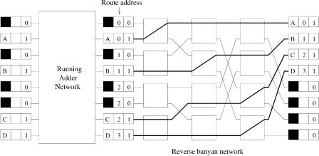
Fig. 5.22 The basic components in a nonblocking copy network.
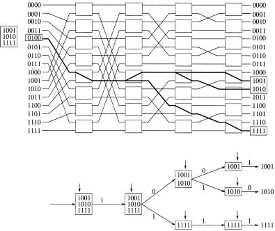
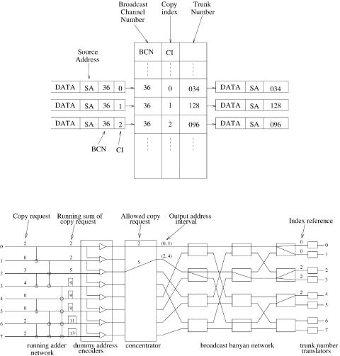
Fig. 5.23 Header translations in the copy network.
network. Based on the resulting sums, the dummy address encoders form new headers with two fields: a dummy address inter®al and an index reference
ŽIR.. The dummy address interval is formed by the adjacent running sums, namely, the minimum ŽMIN. and the maximum ŽMAX.. The index reference is set equal to the minimum of the address interval, and is used later by the trunk number translators to determine the copy index ŽCI.. The broadcast banyan network replicates cells according to a Boolean inter®al spitting algo- rithm based on the address interval in the new header. When a copy finally appears at the desired output, the TNT computes its CI from the output address and the index reference. The broadcast channel number ŽBCN. and the CI form a unique identifier pointing to a trunk number ŽTN., which is added to the cell header and used to route the cell to its final destination.
MULTICAST COPY NETWORKS |
127 |
5.6.1Broadcast Banyan Network
5.6.1.1Generalized Self-Routing Algorithm A broadcast banyan network is a banyan network with switch nodes that are capable of replicating cells. A cell arriving at each node can be either routed to one of the output
links, or replicated and sent out on both links. There are three possibilities and the uncertainty of making a decision is log2 3 s 1.585, which means that the minimum header information for a node is 2 bits.
Figure 5.24 illustrates a generalization of the 1-bit self-routing algorithm to the multi-bit case for a set of arbitrary N-bit destination addresses. When a cell arrives at a node in stage k, the cell routing is determined by the kth bits of all destination addresses in the header. If they are all 0 or all 1, then the cell will be sent out on link 0 or link 1, respectively. Otherwise, the cell and its copy are sent out on both links, and the destination addresses in the header are modified correspondingly to the two cell copies: the header of the cell copy sent out on link 0 or link 1 contains those addresses in the original header with the kth bit equal to 0 or 1, respectively.
Several problems may arise in implementing the generalized self-routing algorithm. First, a cell header contains a variable number of addresses and the switch nodes have to read all of them. Second, the cell header modification depends on the entire set of addresses, which is a processing burden on the switch nodes. Finally, the set of paths from any input to a set of outputs
Fig. 5.24 An input output tree generated by a generalized self-routing algorithm.
128 BANYAN-BASED SWITCHES
form a tree in the network. The trees generated by an arbitrary set of input cells are not link-independent in general, and the network is obviously blocking due to the irregularity of the set of actual destination addresses in the header of each cell. However, fictitious addresses instead of actual addresses can be used in the copy network, where cells are replicated but need not be routed to the actual destinations. The fictitious addresses for each cell then may be arranged to be contiguous so that an address interval consisting of the MIN and the MAX can represent the whole set of fictitious addresses. The address intervals of input cells can be specified to be monotonic to satisfy the nonblocking condition for the broadcast banyan network described below.
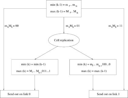
5.6.1.2 Boolean Interval Splitting Algorithm An address inter®al is a set of contiguous N-bit binary numbers, which can be represented by two numbers, namely, the minimum and the maximum. Suppose that a node at stage k receives a cell with the header containing an address interval specified by the two binary numbers minŽk y 1. s m1 . . . mN and maxŽk y 1. s M1 . . . MN , where the argument k y 1 denotes the stage from which the cell came to stage k. The generalized self-routing algorithm gives the direction for cell routing as follows, and as illustrated in Figure 5.25:
If mk s Mk s 0 or mk s Mk s 1, then send the cell out on link 0 or 1, respectively.
Fig. 5.25 The switch node logic at stage k of a broadcast banyan network.
MULTICAST COPY NETWORKS |
129 |
If mk s 0 and Mk s 1, then replicate the cell, modify the headers of both copies Žaccording to the scheme described below., and send each copy out on the corresponding link.
The modification of a cell header is simply splitting the original address interval into two subintervals, as expressed in the following recursion: For the cell sent out on link 0,
minŽ k . s minŽ k y 1. s sm1 . . . mN , maxŽ k . s M1 . . . Mky1 01 . . . 1,
and for the cell sent out on link 1,
minŽ k . s m1 . . . mky1 10 . . . 0,
maxŽ k . s maxŽ k y 1. s M1 . . . MN .
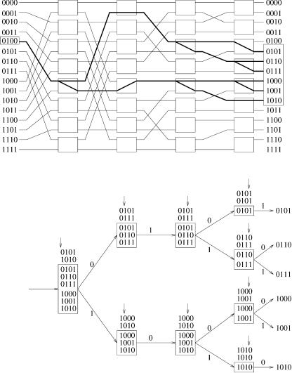
Figure 5.26 illustrates the Boolean interval splitting algorithm. From the rules it is realized that mi s Mi , i s 1, . . . , k y 1, holds for every cell that arrives at stage k. The event mk s 1 and Mk s 0 will never occur.
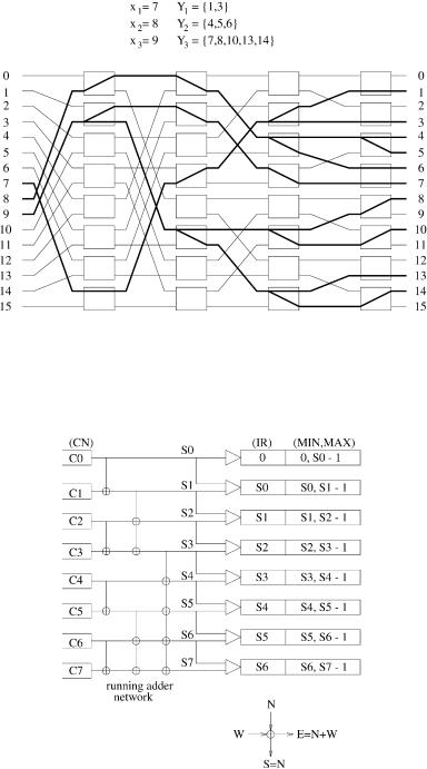
5.6.1.3 Nonblocking Condition of Broadcast Banyan Networks A broadcast banyan network is nonblocking if the active inputs x1, . . . , xk and the corresponding sets of outputs Y1, . . . , Yk satisfy the following:
1. Monotonicity: Y1 Y2 Yk or Y1 Y2 Yk .
2. Concentration: Any input between two active inputs is also active.
The above inequality Yi Yj means that every output address in Yi is less than any output address in Yj. Figure 5.27 illustrates a nonblocking example with active inputs x1 s 7, x2 s 8, x3 s 9, and corresponding outputs Y1 s1, 34, Y2 s 4, 5, 64, Y3 s 7, 8, 10, 13, 144.
5.6.2 Encoding Process
The RAN, together with the DAEs, is used to arrange the destination addresses for each cell so that every eligible cell can be replicated appropriately in the broadcast banyan network without any conflicts. Cell replications in the broadcast banyan network are aided by two processes, an encoding process and a decoding process. The encoding process transforms the set of copy numbers, specified in the headers of incoming cells, into a set of monotone address intervals that form the cell headers in the broadcast banyan network. This process is carried out by a running adder network and a set of dummy address encoders. The decoding process determines the destinations of copies with the TNTs.
130 BANYAN-BASED SWITCHES
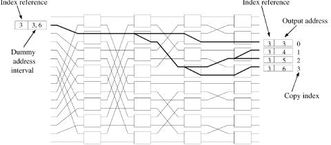
Fig. 5.26 The Boolean interval-splitting algorithm generates the tree while replicating a cell according to the address intervals.
The recursive structure of the log2 N-stage running adder network is illustrated in Figure 5.28. The adder network consists of Ž Nr2.log2 N adders, each with two inputs and two outputs, where a vertical line denotes a pass. The east output is the sum of the west and the north inputs, while the south output just propagates the north input down. The running sums of CN’s are then generated at each port after log2 N stages, before the dummy address encoders form the new headers from adjacent running sums. The new header
MULTICAST COPY NETWORKS |
131 |
Fig. 5.27 An example to demonstrate the nonblocking condition of a broadcast banyan network.
Fig. 5.28 A running adder network and dummy address encoders.
132 BANYAN-BASED SWITCHES
consists of two fields: one is the dummy address interval, represented by two log2 N-bit binary numbers Žthe minimum and the maximum., and the other contains an index reference, which is equal to the minimum of the address interval. Note that the length of each interval is equal to the corresponding copy number in both addressing schemes.
Denoting by Si the ith running sum, the sequence of dummy address intervals will be generated as follows:
Ž0, S0 y 1. , Ž S0 , S1 y 1. , . . . , Ž SNy2 , SNy1 y 1. ,
where the address is allocated beginning with 0. As shown in the previous section, this sequence satisfies the nonblocking condition over the broadcast banyan network.
5.6.3 Concentration
To satisfy the nonblocking condition of the broadcast banyan network, idle inputs between active inputs must be eliminated. This function should be performed before cells enter the broadcast banyan network, e.g., prior to the RAN or right after the DAE in Figure 5.22. A reverse banyan network is thus used to concentrate active inputs into a contiguous list. As illustrated in Figure 5.29, the routing address in the reverse banyan network is determined by the running sums over activity bits to produce a set of continuous monotonic addresses.
Fig. 5.29 An input concentrator consists of a running adder network and a reverse banyan network.
MULTICAST COPY NETWORKS |
133 |
5.6.4 Decoding Process
When a cell emerges from the broadcast banyan network, the address interval in its header contains only one address, that is, according to the Boolean interval-splitting algorithm,
minŽlog2 N . s maxŽlog2 N . s output address.
The cell copies belonging to the same broadcast channel should be distinguished by the CI, which is determined at the output of the broadcast banyan network Žsee Fig. 5.30. by,
CI s output address y index reference.
Recall that the index reference is initially set equal to the minimum of the address interval.
A TNT is used to assign the actual address to each cell copy so that it will be routed to its final destination in the succeeding point-to-point switch. TN assignment can be accomplished by a simple table lookup in which the identifier Žsearching key. consists of the BCN and the CI associated with each cell. When a TNT receives a cell copy, it first converts the output address and IR into the CI, and then replaces the BCN and CI with the corresponding TN in the translation table. The translation process is illustrated in Figure 5.31.
5.6.5 Overflow and Call Splitting
Overflow will occur in the RAN of the copy network when the total number of copy requests exceeds the capacity of the copy network. If partial service Žalso called call splitting. is not allowed in cell replication and a cell must
Fig. 5.30 Computation of copy indexes.
134 BANYAN-BASED SWITCHES
Fig. 5.31 Trunk number translation by table lookup.
Fig. 5.32 An 8 8 nonblocking copy network without call splitting: Only five instead of eight cell copies are allowed in this time slot.
generate all its copies in a time slot, then the throughput may be degraded when overflow occurs. As illustrated in Figure 5.32, overflow occurs at port 3, and only five cell copies are allowed, although more than eight requests are available.
5.6.6 Overflow and Input Fairness
Overflow will also introduce unfairness among incoming cells, because the starting point of the RAN is fixed. Since the calculation of the running sum always starts from input port 0 in every time slot, lower-numbered input ports have higher service priorities than higher numbered ports.
MULTICAST COPY NETWORKS |
135 |
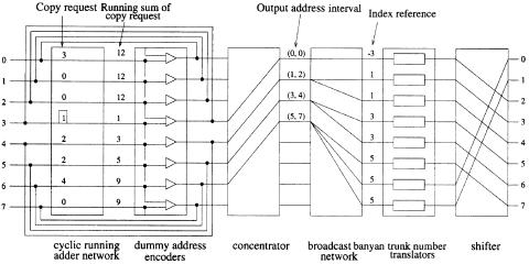
This unfairness problem will be solved if the RAN is redesigned to calculate the running sums cyclically starting from any input port, and the starting point of computing the running sums in every time slot is determined adaptively by the overflow condition in the previous time slot. Such a cyclic RAN ŽCRAN. is illustrated in Figure 5.33. The current starting point is port 3, call splitting is performed at port 6, and the new starting point in the next slot will be port 6. The negative index reference y3, provided by the DAE, implies that the copy request from port 3 is a residual one, and three copies have been generated in the previous time slot.
5.6.6.1 A. Cyclic Running Adder Network Figure 5.34 shows the structure of an 8 8 CRAN. The associated cell header format consists of three fields: starting indicator ŽSI., running sum ŽRS., and routing address ŽRA.. Only one port, which is the starting point, has a nonzero SI initially. The RS field is initially set to the number of copies requested by the input cell. The RA field is initially set to 1 if the port is active; otherwise it is set to 0. At the output of the RAN, the RA field will carry the running sum over activity bits, to be used as the routing address in the following concentrator.
A set of cyclic passing paths is implemented in each stage of the CRAN, so that recursive computation of running sums can be done cyclically. In order to emulate the actual running sum computation from a starting point, however, some passing paths should be virtually cut, as illustrated in Figure 5.34, which is equivalent to having the shaded nodes ignore their links while computing the running sums. These nodes are preceded by a cell header with the SI field equal to 1, as it is propagated from the starting point over the CRAN. The header modification in a node is summarized in Figure 5.35.
The next starting point will remain the same unless overflow occurs, in which case the first port facing the overflow will be the next starting point. If
Fig. 5.33 A CRAN in an 8 8 copy network.