

Broadband Packet Switching Technologies
.pdf76 INPUT-BUFFERED SWITCHES
Fig. 3.20 One-scheduling-phase and two-scheduling-phase time slots.
The necessary condition can be shown by the example as shown below. Since the speedup 2 y 1rN represents a nonintegral distribution of arbitration phases per slot between one and two, we first describe how scheduling phases are distributed. A speedup of 2 y 1rN corresponds to having one truncated time slot out of every N time slots; the truncated time slot has just one scheduling phase, whereas the other N y 1 time slots have two scheduling phases each. Figure 3.20 shows the difference between one-phase and two-phase time slots. We assume that the scheduling algorithm does not know in advance whether a time slot is truncated.
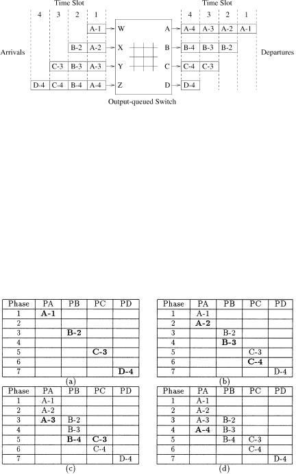
Recall that a cell is represented as a tuple Ž P, TL., where P represents which output port the cell is destined to and TL represents the time to leave for the cell. For example, the cell ŽC, 7. must be scheduled for port C before the end of time slot 7.
The input traffic pattern that provides the lower bound for an N N input output-queued switch is given as follows. The traffic pattern spans N time slots, the last of which is truncated:
1.In the first time slot, all input ports receive cells destined for the same output port, P1.
2.In the second time slot, the input port that had the lowest TL in the previous time slot does not receive any more cells. In addition, the rest of the input ports receive cells destined for the same output port, P2 .
3.In the ith time slot, the input ports that had the lowest TL in each of the i y 1 previous time slots do not receive any more cells. In addition, the rest of the input ports must receive cells destined for the same output port, Pi.
One can repeat the traffic pattern just mentioned as many times as is required to create arbitrarily long traffic patterns. Figure 3.21 shows the
OUTPUT-QUEUING EMULATION |
77 |
Fig. 3.21 Lower-bound input traffic pattern for a 4 4 switch.
above sequence of cells for a 4 4 switch. The departure events from the output-queued switch are depicted on the right, and the arrival events are on the left. For simplicity, we present the proof of our lower bound on this 4 4 switch instead of a general N N switch.
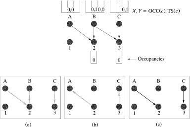
Figure 3.22 shows the only possible schedule for transferring these cells across in seven phases. Of the four time slots, the last one is truncated, giving a total of seven phases. Cell A-1 must leave the input side during the first phase, since the input output-queued switch does not know whether the first time slot is truncated. Similarly, cells B-2, C-3, and D-4 must leave during the third, fifth, and seventh phases, respectively wsee Fig. 3.22Ža.x. Cell A-2 must leave the input side by the end of the third phase. However, it cannot leave during the first or the third phase, because of contention. Therefore, it must
Fig. 3.22 Scheduling order for the lower-bound input traffic pattern in Figure 3.21.
78 INPUT-BUFFERED SWITCHES
depart during the second phase. Similarly, cells B-3 and C-4 must depart during the fourth and sixth phases, respectively wsee Fig. 3.22Žb.x. Continuing this elimination process wsee Fig. 3.22Žc. and Žd.x, there is only one possible scheduling order. For this input traffic pattern, the switch needs all seven phases in four time slots, which corresponds to a minimum speedup of 74 Žor 2 y 14 .. The proof of the general case for an N N switch is a straightforward extension of the 4 4 example.
3.5 LOWEST-OUTPUT-OCCUPANCY-CELL-FIRST ALGORITHM (LOOFA)
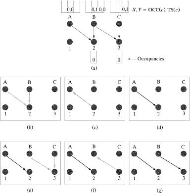
The LOOFA is a work-conserving scheduling algorithm w16x. It provides 100% throughput and a cell delay bound for feasible traffic, using a speedup of 2. An input output-queued architecture is considered. Two versions of this scheme have been presented: the greedy and the best-first. This scheme considers three different parameters associated with a cell, say cell c, to perform a match: the number of cells in its destined output queue, or output occupancy, OCCŽc.; the timestamp of a cell, or cell age, TSŽc.; and the smallest port number, to break ties. Under the speedup of 2, each time slot has two phases. During each phase, the greedy ®ersion of this algorithm works as follows Žsee Fig. 3.23 for an example.:
1.Initially, all inputs and outputs are unmatched.
2.Each unmatched input selects an active VOQ Ži.e., a VOQ that has at least one cell queued. going to the unmatched output with the lowest
Fig. 3.23 A matching example with the greedy LOOFA.
LOWEST-OUTPUT-OCCUPANCY-CELL-FIRST ALGORITHM (LOOFA) |
79 |
occupancy, and sends a request to that output. Ties are broken by selecting the smallest output port number. See Figure 3.23Ža..
3.Each output, on receiving requests from multiple inputs, selects the one with the smallest OCC and sends the grant to that input. Ties are broken by selecting the smallest port number.
4.Return to step 2 until no more connections can be made.
An example of the greedy version is shown in Figure 3.23. The tuple X, Y in the VOQ represents the output occupancy OCCŽc. and the timestamp TSŽc. of cell c, respectively. In the upper part of the figure, the arrows indicate the destinations for all different cells at the input ports. The gray arrows in the lower part of the figure indicate the exchange of requests and grants. The black arrows indicate the final match. Part Ža. shows that each input sends a request to the output with the lowest occupancy. Output 2 receives two requests, one from A and the other from B, while output 3 receives a request from input C. Part Žb. illustrates that, between the two requests, output 2 chooses input A, the one with lower TS. Output 3 chooses the only request, input C.
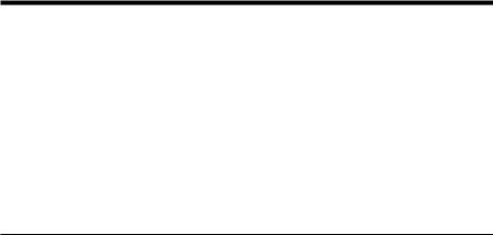
The best-first version works as follows:
1.Initially, all inputs and outputs are unmatched.
2.Among all unmatched outputs, the output with the lowest occupancy is selected. Ties are broken by selecting the smallest output port number. All inputs that have a cell destined for the selected output send a request to it.
3.The output selects the cell request input with the smallest time stamp and sends the grant to the input. Ties are broken by selecting the smallest input port number.
4.Return to step 2 until no more connections can be made Žor N iterations are completed..
Figure 3.24 shows a matching example with the best-first version. The selection of the output with the lowest OCCŽc. results in a tie: Outputs 2 and 3 have the lowest OCC. This tie is broken by selecting output 2, since this port number is the smaller. Therefore, inputs A and B send a request to this output as shown in part Žb., while part Žc. illustrates that output 2 grants the oldest cell, input A. Part Žd. shows the matching result after the first iteration. The second iteration begins in part Že. when output 3 is chosen as the unmatched output port with the lowest OCC with requests from inputs B and C. Input B is chosen in part Žf. for its lowest TSŽc.. Part Žg. depicts the final match.
Both algorithms achieve a maximal matching, with the greedy version achieving it in less iterations. On the other hand, it has been proven that, when combined with the oldest-cell-first input selection scheme, the best-first
80 INPUT-BUFFERED SWITCHES
Fig. 3.24 A matching example with the best-first version of LOOFA.
version provides delay bounds for rate-controlled input traffic under a speedup of 2. Denote by Da and Do the arbitration delay and the output queuing delay of any cell. It can be shown that that Da F 4 NrŽS y 1. and
1.M. Ajmone, A. Bianco, and E. Leonardi, ‘‘RPA: a simple efficient and flexible policy for input buffered ATM switches,’’ IEEE Commun. Lett., vol. 1, no. 3, pp. 83 86, May 1997.
2.T. Anderson, S. Owicki, J. Saxe, and C. Thacker, ‘‘High speed scheduling for local area networks,’’ Proc. 5th Int. Conf. on Architecture Support for Programming Languages and Operating Systems, pp. 98 110, Oct. 1992.
3.H. J. Chao and J. S. Park, ‘‘Centralized contention resolution schemes for a large-capacity optical ATM switch,’’ Proc. IEEE ATM Workshop, Fairfax, VA, May 1998.
REFERENCES 81
4.H. J. Chao, ‘‘Satrun: a terabit packet switch using dual round-robin,’’ IEEE Commun. Mag., vol. 38, no. 12, pp. 78 79, Dec 2000.
5.A. Charny, P. Krishna, N. Patel, and R. Simcoe, ‘‘Algorithm for providing
bandwidth and delay guarantees in input-buffered crossbars with speedup,’’ Proc. IEEE IWQoS 98, May 1998, pp. 235 244.
6.J. S.-C. Chen and T. E. Stern, ‘‘Throughput analysis, optimal buffer allocation, and traffic imbalance study of a generic nonblocking packet switch,’’ IEEE J. Select. Areas Commun., vol. 9, no. 3, pp. 439 449, Apr. 1991.
7.S.-T. Chuang, A. Goel, N. McKeown, and B. Prabhakar, ‘‘Matching output queueing with a combined inputroutput-queued switch,’’ IEEE J. Select. Areas Commun., vol. 17, no. 6, pp. 1030 1039, Jun. 1999.
8.A. Descloux, ‘‘Contention probabilities in packet switching networks with strung input processes,’’ Proc. ITC 12, 1988.
9.H. ElGebaly, J. Muzio, and F. ElGuibaly, ‘‘Input smoothing with buffering: a new technique for queuing in fast packet switching,’’ Proc. IEEE Pacific Rim Conf. on Communications, Computer, and Signal Processing, pp. 59 62, 1995.
10.K. Genda, Y. Doi, K. Endo, T. Kawamura, and S. Sasaki, ‘‘A 160 Gbrs ATM
switching system using an internal speed-up crossbar switch,’’ Proc. GLOBECOM
94, Nov. 1994, pp. 123 133, 1998.
11.J. N. Giacopelli, W. D. Sincoskie, and M. Littlewood, ‘‘Sunshine: a high performance self routing broadband packet switch architecture,’’ Proc. Int. Switching Symp., Jun. 1990.
12.R. Guerin and K. N. Sivarajan, ‘‘Delay and throughput performance of speeded-up input-queueing packet switches,’’ IBM Research Report RC 20892, Jun. 1997.
13.M. G. Hluchyj and M. J. Karol, ‘‘Queueing in high-performance packet switching,’’ IEEE J. Select. Areas Commun., vol. 6, no. 9, pp. 1587 1597, Dec. 1988.
14.A. Huang and S. Knauer, ‘‘Starlite: a wideband digital switch,’’ Proc. IEEE Globecom 84, pp.121 125, Dec. 1984.
15.I. Iliadis and W. E. Denzel, ‘‘Performance of packet switches with input and output queueing,’’ Proc. ICC 90, Atlanta, GA, pp. 747 753, Apr. 1990.
16.P. Krishna, N. Patel, A. Charny, and R. Simcoe, ‘‘On the speedup required for work-conserving crossbar switches,’’ IEEE J. Select. Areas Commun., vol. 17, no. 6, June 1999.
17.R. O. LaMaire and D. N. Serpanos, ‘‘Two dimensional round-robin schedulers for packet switches with multiple input queues,’’ IEEErACM Trans. on Network- ing, Vol. 2, No. 5, Oct. 1994.
18.T. T. Lee, ‘‘A modular architecture for very large packet switches,’’ IEEE Trans. Commun., vol. 38, no. 7, pp. 1097 1106, Jul. 1990.
19.S. Q. Li, ‘‘Performance of a nonblocking space-division packet switch with correlated input traffic,’’ IEEE Trans. Commun., vol. 40, no. 1, pp. 97 107, Jan. 1992.
20.S. C. Liew, ‘‘Performance of various input-buffered and output-buffered ATM
switch design principles under bursty traffic: simulation study,’’ IEEE Trans. Commun., vol. 42, no. 2r3r4, pp. 1371 1379, Feb.rMar.rApr. 1994.
21.P. Newman, ‘‘A fast packet switch for the integrated services backbone network,’’ IEEE J. Select. Areas Commun., vol. 6, pp. 1468 1479, 1988.
82 INPUT-BUFFERED SWITCHES
22.M. A. Marsan, A. Bianco, P. Giaccone, E. Leonardi, and F. Neri, ‘‘Packet scheduling in input-queued cell-based switches,’’ IEEE J. Select. Areas Commun., 1998, 1998.
23.N. McKeown, P. Varaiya, and J. Warland, ‘‘Scheduling cells in an input-queued switch,’’ IEEE Electron. Lett., pp. 2174 2175, Dec. 9th 1993.
24.N. McKeown, ‘‘Scheduling algorithms for input-queued cell switches,’’ Ph.D. thesis, Uni®ersity of California at Berkeley, 1995.
25.N. McKeown, ‘‘The iSLIP scheduling algorithm for input-queued switches,’’ IEEErACM Trans. Networking, vol. 7, no. 2, pp. 188 201, Apr. 1999.
26.A. Mekkitikul and N. McKeown, ‘‘A starvation-free algorithm for achieving 100% throughput in an input-queued switch,’’ in Proc. ICCCN 96, 1996.
27.Y. Oie, M. Murata, K. Kubota, and H. Miyahara, ‘‘Effect of speedup in nonblocking packet switch,’’ Proc. ICC 89, pp. 410 414, Jun. 1989.
28.A. Pattavina and G. Bruzzi, ‘‘Analysis of input and output queueing for nonblocking ATM switches,’’ IEEErACM Trans. Networking, vol. 1, no. 3, pp. 314 328, Jun. 1993.
29.B. Prabhakar and N. McKeown, ‘‘On the speedup required for combined input and output queued switching,’’ Technical Report, CSL-TR-97-738, Computer Lab., Stanford University.
30. A. Smiljanic,´ R. Fan, and G. Ramamurthy, ‘‘RRGS round-robin greedy scheduling for electronicroptical switches,’’ Proc. IEEE Globecom 99, pp. 1244 1250, 1999.
31.A. Smiljanic,´ ‘‘Flexible bandwidth allocation in terabit packet switches,’’ Proc.
IEEE Conf. on High-Performance Switching and Routing, pp. 223 241, 2000.
32. I. Stoica and H. Zhang, ‘‘Exact |
emulation |
of an |
output |
queueing switch by |
a combined input and output |
queueing |
switch,’’ |
Proc. |
IEEE IWQoS 98, |
pp. 218 224, May 1998. |
|
|
|
|
Broadband Packet Switching Technologies: A Practical Guide to ATM Switches and IP Routers
H. Jonathan Chao, Cheuk H. Lam, Eiji Oki
Copyright 2001 John Wiley & Sons, Inc. ISBNs: 0-471-00454-5 ŽHardback.; 0-471-22440-5 ŽElectronic.
CHAPTER 4
SHARED-MEMORY SWITCHES
In shared-memory switches, all input and output ports have access to a common memory. In every cell time slot, all input ports can store incoming cells and all output ports can retrieve their outgoing cells Žif any.. A shared-memory switch works essentially as an output-buffered switch, and therefore also achieves the optimal throughput and delay performance. Furthermore, for a given cell loss rate, a shared-memory switch requires less buffers than other switches.
Because of centralized memory management to achieve buffer sharing, however, the switch size is limited by the memory readrwrite access time, within which N incoming and N outgoing cells in a time slot need to be accessed. As shown in the formula given below, the memory access cycle must be shorter than 1r2 N of the cell slot, which is the transmission time of a cell on the link:
|
|
cell length |
|
memory access cycle F |
|
|
. |
|
|
||
2 |
N link speed |
||
For instance, with a cell slot of 2.83 s Ž53-byte cells at the line rate of 149.76 Mbitrs, or 155.52 Mbitrs 26r27. and with a memory cycle time of 10 ns, the switch size is limited to 141.
Several commercial ATM switch systems based on the shared memory architecture provide a capacity of several tens of gigabits per second. Some people may argue that memory density doubles every 18 months and so the memory saving by the shared-memory architecture is not that significant. However, since the memory used in the ATM switch requires high speed
83
84 SHARED-MEMORY SWITCHES
Že.g., 5 10-ns cycle time., it is expensive. Thus, reducing the total buffer size can considerably reduce the implementation cost. Some sharedmemory switch chip sets have the capability of integrating with other space switches to build a large-capacity switch Že.g., a few hundred gigabits per second..
Although the shared-memory switch has the advantage of saving buffer size, the buffer can be occupied by one or a few output ports that are congested and thus leave no room for other cells destined for other output ports. Thus, there is normally a cap on the buffer size that can be used by any output port.
The following sections discuss different approaches to organize the shared memory and necessary control logics. The basic idea of the shared-memory switch is to use logical queues to link the cells destined for the same output port. Section 4.1 describes this basic concept, the structure of the logical queues, and the pointer processing associated with writing and reading cells to and from the shared memory. Section 4.2 describes a different approach to implement the shared-memory switch by using a content-addressable memory ŽCAM. instead of a random access memory ŽRAM. as in most approaches. Although CAM is not as cost-effective and fast as RAM, the idea of using CAM to implement the shared-memory switch is interesting because it eliminates the need of maintaining logical queues. The switch size is limited by the memory chip’s speed constraint, but several approaches have been proposed to increase it, such as the space time space approach in Section 4.3 and multistage shared-memory switches in Section 4.4. Section 4.5 describes several shared-memory switch architectures to accommodate multicasting capability.
4.1 LINKED LIST APPROACH
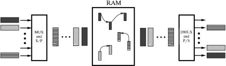
Figure 4.1 illustrates the concept of the shared-memory switch architecture. Cells arriving on all input lines are time-division multiplexed into a single stream, which is then converted to a parallel word stream and fed to the
Fig. 4.1 Logical queues in a shared-memory switch.
LINKED-LIST APPROACH |
85 |
common memory for storage. Internally to the memory, cells are organized into separate logical queues, one for each output line. Cells destined for the same output port are linked together in the same logical queue. On the other hand, an output stream of cells is formed by retrieving the head-of-line ŽHOL. cells from the output queues sequentially, one per queue; the output stream is then time-division demultiplexed, and cells are transmitted on the output lines. Each logical queue is confined by two pointers, the head pointer ŽHP. and the tail pointer ŽTP.. The former points to the first cell of a logical queue, while the latter points to the last cell of a logical queue or to a vacant location to which the next arriving cell will be stored.
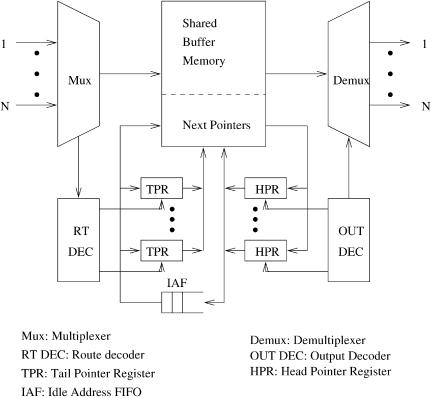
Figure 4.2 depicts a linked-list-based shared-memory switch where a logical queue is maintained for each output to link all cells in the memory destined for the output. Each logical queue is essentially operated as a FIFO queue.
The switch operation is as follows. Incoming cells are time-division multiplexed to two synchronized streams: a stream of data cells to the memory,
Fig. 4.2 Basic structure of a linked-list-based shared-memory switch.