
Broadband Packet Switching Technologies
.pdf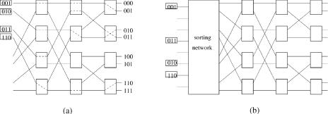
106 BANYAN-BASED SWITCHES
Fig. 5.4 An example showing that the banyan network is nonblocking for sorted inputs. Žb. Nonblocking sort banyan network.
See Figure 5.4. Suppose the banyan network is preceded by a network that concentrates the cells and sorts the cells according to their output destinations. The overall sort banyan network will be internally nonblocking.
5.2 BATCHER-SORTING NETWORK
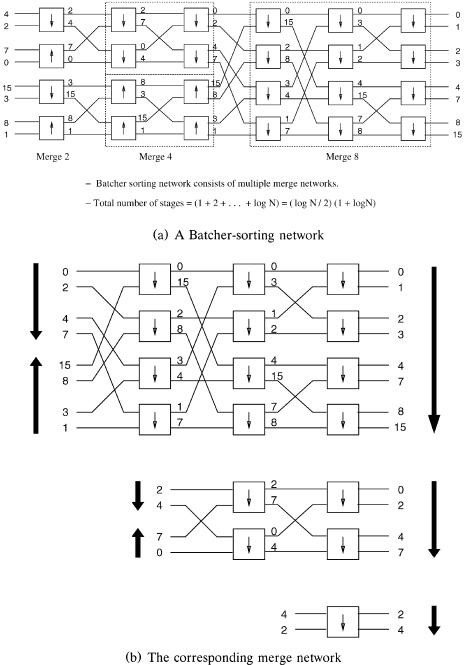
A sorting network is formed by a series of merge networks of different sizes. Figure 5.5Ža. shows an 8 8 Batcher-sorting network w3x consisting of merge networks of three different sizes. A merge network wsee Fig. 5.5Žb.x is built from 2 2 sorting elements in stages, and the pattern of exchange connections between each pair of adjacent stages is the same as in a banyan network. We can observe that, if the order of the destinations of the first half input cells is ascending and that of the second half is descending, then the merge network will sort the cells into an ascending list at the outputs. An 8 8 sorting network will be formed if an 8 8 merge network is preceded by two 4 4 merge networks and four 2 2 merge Žsorting. elements. A completely random list of eight input cells will be first sorted into four sorted lists of two cells, then two sorted lists of four cells, and finally a sorted list of eight cells.
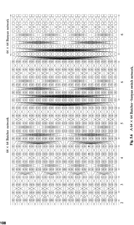
A N N merge network consists of log2 N stages and Ž N log2 N .r2 elements. A sorting network has 1 q 2 q qlog2 N s Žlog2 N .Žlog2 N q 1.r2 stages and Ž N log2 N .Žlog2 N q 1.r4 elements. Figure 5.6 shows a 64 64 Batcher-banyan switch network, where the last six stages of switch elements belong to the banyan network.
BATCHER-SORTING NETWORK |
107 |
Fig. 5.5 Basic structure of a Batcher-sorting network.
BATCHER-SORTING NETWORK |
109 |
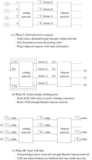
Fig. 5.7 The three-phase algorithm.
110 BANYAN-BASED SWITCHES
5.3 OUTPUT CONTENTION RESOLUTION ALGORITHMS
5.3.1 Three-Phase Implementation
The following three-phase algorithm is a solution for output contention resolution in a Batcher banyan switch Žsee Figure 5.7..
In the first Žarbitration. phase of the algorithm, each input port i sends a short request only consisting of a source destination pair to the sorting network, where the requests are sorted in nondecreasing order according to the destination address. In other words, conflicting requests are sorted at adjacent positions, and a request wins the contention only if its destination is different from the one above it in the sorted list.
As the input ports do not know the result of the arbitration, the requests that won the arbitration must send an acknowledgment to the input ports via an interconnection network in the second phase Žthe so-called acknowledgment phase.. The feedback network in Figure 5.7Žb. consists of N fixed connections, each from an output of the Batcher network to the corresponding input of the Batcher network. Each acknowledgment carries the source that has won the contention back to an input of the Batcher network. These acknowledgments Žsources. are routed through the entire Batcher banyan network at distinct outputs according to the source address. When these acknowledgments are feedbacked to the inputs through an identical fixed network, each input port know if it has won the contention. The input ports that finally receive an acknowledgment are guaranteed output-conflict-free.
These input ports then transmit the full cell in the third and final phase wsee Fig. 5.7Žc.x through the same Batcher banyan network. Input ports that fail to receive an acknowledgment retain the cell in a buffer for a retry in the next time slot when the three-phase cycle is repeated.
5.3.2 Ring Reservation
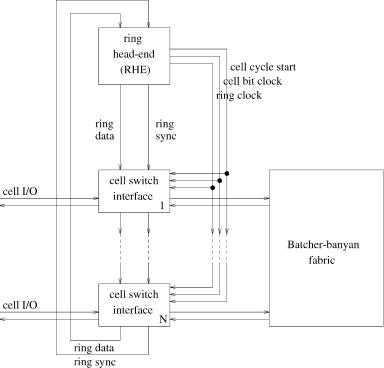
A Batcher banyan cell switch design with ring reservation is shown in Figure 5.8 w5x. The switch comprises the Batcher banyan switch fabric, several switch interfaces, and a ring head-end ŽRHE. and timing generator.
A switch interface supports ring reservation and provides input cell buffering, synchronization of cells sent to the switch fabric, and output cell buffering. Cells entering the switch are buffered in a FIFO until they can participate in the reservation procedure. When an output is successfully reserved, the cell is delivered to the switch fabric at the beginning of the next cell cycle, and the next queued cell can begin to participate in the reservations. When the cell emerges from the output of the switch fabric, it is buffered in the interface before being transmitted to its destination.
The RHE provides two switch synchronization signals Žbit clock and cell cycle start. and three ring reservation signals Žring clock, ring data, and ring sync.. The ring data signal is a series of output reservation bits, and the ring sync signal indicates the position of the first output port in the ring data
OUTPUT CONTENTION RESOLUTION ALGORITHMS |
111 |
Fig. 5.8 A Batcher banyan switch with ring reservation.
series. These two signals are circulated through the RHE and switch interfaces, one bit at a time, during the reservation process. Ring reservation is performed at the beginning of each cell cycle after every ring interface has the header of the oldest cell copies. The ring data in the RHE and each ring interface is cleared ŽIDLE. at every cell cycle start. The ring data series then begins to circulate through the interface bit by bit. Each interface maintains a port counter, which is incremented in every ring data bit time. The port counter is compared with the destination of the oldest cell in every bit time to indicate if the cell is destined for the output in the next bit time. During each ring data bit time, each switch interface examines both the ring sync and the ring data bit. If the ring sync signal is true, which means the next ring data bit corresponds to the first output, then the port counter is reset in the next bit time. If the destination of the cell matches with the port counter and the ring data bit is IDLE, the switch interface writes BUSY on the ring to show that the output has been occupied in the next switch cycle. If the ring data bit is already BUSY, or if the port counter does not match the destination of the oldest cell, the ring data bit is left unchanged. Since each interface makes no more than one reservation per switch cycle, no collisions can take place in the switch fabric. While the ring reservation is being
112 BANYAN-BASED SWITCHES
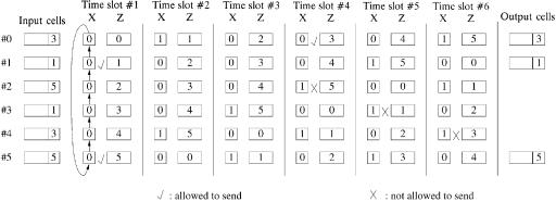
Fig. 5.9 The implementation of the ring reservation scheme.
performed, the cells reserved in the previous switch cycle are transmitted to the switch fabric.
As shown in Figure 5.9, at the first time slot, the output port addresses of cells from input ports 1 and 5 are matched, and checkmarks are used to indicate that the cells can be sent to these output ports. The token bits x1 and x5 are set to one to indicate that output ports 1 and 5 are already reserved. All the token bits are shifted up one bit, and the counter values are also modulo-increased by one for the second time slot. There are no matches found at the second and the third time slots. At the fourth time slot, the output port addresses of cells from input ports 0 and 2 are matched. Since output port 5 is already reserved for the cell in the previous time slot, which is indicated by the value of the token bit x2 , the cell at input port 2 cannot be sent. Similarly, for the fifth and the sixth time slots, the cells at input ports 3 and 4 cannot be sent to output ports 1 and 3, respectively, since those output ports are already reserved in the previous time slots. At the end, cells from the input ports that are checked are the ones winning the contention.
In this example, since there are six input ports, the arbitration cycle can be completed within six time slots. This scheme uses the serial mechanism and, in general, the arbitration cycle can be done within an N-bit time slot, where N is the number of inputroutput ports of the switch. This will become the bottleneck when the number of ports of the switch is large. However, by arbitrarily setting the appropriate values for the counters prior to the arbitration, this scheme provides fairness among the input ports. Another advantage of this scheme is that it can be employed at the input of any type of switch fabric.
5.4 THE SUNSHINE SWITCH
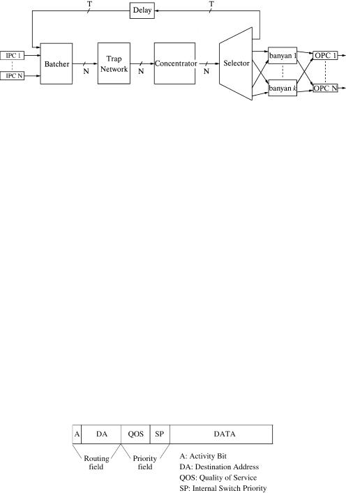
The Sunshine switch uses the combination of a Batcher-sorting network and parallel banyan routing networks to provide more than one path to each destination. Figure 5.10 shows a block diagram of the architecture. The k
THE SUNSHINE SWITCH |
113 |
Fig. 5.10 Block diagram of the Sunshine switch.
parallel banyan routing networks provide k independent paths to each output. If more than k cells request a particular output during a time slot, then some excess cells overflow into a shared recirculating queue and then are resubmitted to the switch at dedicated input ports. The recirculating queue consists of T parallel loops and T dedicated inputs to the Batchersorting network. Each recirculating loop can hold one cell. A delay block is put within the loops to align recirculated cells with those new arrivals from the input port controllers ŽIPCs. in the next time slot. During each time slot, the Batcher network sorts newly arrived and recirculated cells in the order of destination address and priority. This enables the trap network to resolve output port contention by selecting the k highest priority cells for each destination address. Since there are k parallel banyan networks, each output can accept k cells in a time slot. When there are more than k cells destined for an output, the excess will enter the recirculating queue. The concentrator and the selector will direct the excess cells to the recirculating loops, while those cells selected for routing will be forwarded to the banyan networks.
Each cell is inserted with a control header at the input port controller. The header format is shown in Figure 5.11. It contains two control fields: a routing field and a priority field; both are ordered starting with the most significant bit. In the routing field, the first bit is a cell activity bit to indicate if the cell contains valid information Ž A s 1., or the cell is empty Ž A s 0.. Then the destination address ŽDA. field identifying the desired output port follows. The priority field consists of the quality of service ŽQoS. indicator and the internal switch priority ŽSP.. The QoS field distinguishes cells from higher-priority services such as circuit emulation and from lower-priority
Fig. 5.11 The header format.
114 BANYAN-BASED SWITCHES
services such as connectionless service, and ensures that higher-priority cells will be routed before lower-priority cells when conflicts arise. The SP field is used internally by the switch to indicate the number of time slots that a cell has been delayed, and gives higher priority to recirculated cells. This causes cells from a given source to be routed in sequence.
When the cells are sorted, they are arranged in ascending order of destination address. The priority field, where a higher numerical value represents a higher priority level, appears as an extension of the routing field. This causes cells destined for the same output to be arranged in descending order of priority. In the trap network, the address of every cell is compared with that of the cell k positions above. If a cell has the same address as the cell k positions above, which indicates that there are at least k cells with higher priority, then the cell is marked to be recirculated, and its routing field is interchanged with the priority field because the priority field is more important for the subsequent operation of the concentration sorting network against the recirculation loss. Otherwise, the cell is one of the k Žor less. highest-priority cells for the address, and is set to be routed.
In the Batcher concentration network, there are two groups of cells, one to be routed and the other to be recirculated; each is sorted into a contiguous list. Then the group of cells to be routed forms a list in ascending order of the destination address, to avoid subsequent internal blocking in the banyan networks.The group of cells to be recirculated is sorted into a separate contiguous list according to priority. However, the cells to be recirculated are arranged in the order of destination address. If the recirculating queue overflows, the cells destined for the higher-numbered outputs are more likely to be dropped than those for lower-numbered outputs.
Cells are then directed to the selector, which differentiates the two groups and directs them to k banyan networks and to T recirculators, respectively. Cells that enter the recirculators will have their routing and priority fields interchanged back into the original format. Their priority ŽSP. is incremented as they are recirculated.
The outputs of the selectors are spread among the k banyan networks by connecting every kth output to the same banyan network. This ensures every two cells destined for the same output are separated into different banyan networks. The cells in each banyan network still constitute a contiguous list destined for distinct outputs, which satisfies the nonblocking condition in a banyan network. Every cell then reaches the desired output of a banyan network, and all corresponding outputs are grouped together to an output queue in the output port controller ŽOPC..
5.5 DEFLECTION ROUTING
5.5.1 Tandem Banyan Switch
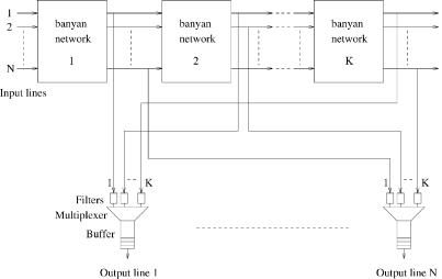
Figure 5.12 shows the tandem banyan switching fabric ŽTBSF. w19x. It consists of multiple banyan networks in series. When two cells contend at any node in
DEFLECTION ROUTING |
115 |
Fig. 5.12 Tandem banyan switching fabric.
a banyan network, one of them will just be deflected to the wrong output of the node and finally arrive at an incorrect destination of the banyan network. The deflected cell is then forwarded to the next banyan network. This process continues again and again until the cell reaches the desired output or it gets out of the last banyan network at an undesired output and is regarded as lost. Each output of every banyan network is connected to the corresponding output buffer. A cell is marked misrouted when it gets deflected in a banyan network, to distinguish it from the properly routed cells and avoid affecting their routing at later stages within the network. At outputs of each banyan network, the cells that have reached their destinations are extracted from the fabric and placed in output port buffers. Note that the load of successive banyan networks decreases and so does the likelihood of conflicts. With a sufficiently large number of banyan networks, it is possible to reduce the cell loss to desired levels. Numerical results show that each additional banyan network improves the cell loss probability by one order of magnitude.
The operation of the TBSF is as follows. A switching header is appended to each cell when it enters the switching fabric, and it comprises the following four fields:
Acti®ity Bit a: It indicates whether the slot contains a cell Ža s 1. or is empty Ža s 0..
Conflict Bit c: It indicates whether the cell has already been misrouted
at some previous stage of the present network Žc s 1. or not Žc s 0..
Priority Field P: It is optional and is used if multiple priority is supported over the switch.
Address Field D: It contains the destination addresses, d1, d2 , . . . , dn Žn s log2 N ..
