

Broadband Packet Switching Technologies
.pdf136 BANYAN-BASED SWITCHES
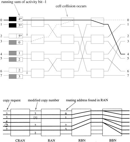
Fig. 5.34 An 8 8 cyclic running adder network.
Fig. 5.35 The operation of a node in a CRAN.
we denote the starting point as port 0, and number the other ports from 1 to N y 1 in a cyclic manner, then the SI bit that indicates the next starting point is updated with adjacent RS fields at each port as follows:
SI 0 s ½1
0otherwise.
and |
|
SI i s ½1 if RSiy1 |
F N and RSi N, |
0otherwise,,
where i s 1, 2, . . . , N y 1.
In order to support call splitting, every input port should know how many copies are served in each time slot. This piece of information is called the starting copy number ŽSCN.. A set of feedback loops is then established to send this information back to input ports after it is determined with adjacent
|
MULTICAST COPY NETWORKS 137 |
|
running sums as follows: |
|
|
and |
SCN0 s RS0 , |
|
|
|
|
SCNi s ½ |
minŽ N y RSiy1 , RSi y RSiy1 . |
if RSiy1 N |
0 |
otherwise |
|
5.6.6.2 Concentration The starting point in a CRAN may not be port 0, and the resulting sequence of routing addresses in the RBN may not be continuous monotone. As illustrated in Figure 5.36, internal collisions may occur in the RBN.
Fig. 5.36 Cyclic monotone addresses give rise to cell collisions in a reverse banyan network. Port 2 and port 6 are idle.
Fig. 5.37 An additional RAN is used to concentrate active cells. The starting point is marked by encircling its copy request.
138 BANYAN-BASED SWITCHES
This problem can be solved if an additional RAN with fixed starting point Žport 0. is added in front of the RBN. As shown in Figure 5.37, this additional RAN will recalculate the running sums of RAs so that the resulting sequence of RAs becomes continuous monotone.
REFERENCES
1.H. Ahmadi and W. E. Denzel, ‘‘A survey of modern high-performance switching techniques,’’ IEEE J. Select. Areas Commun., vol. 7, no. 7, pp. 1091 1103, Sep. 1989.
2.P. Baran, ‘‘On distributed communications networks,’’ IEEE Trans. Commun., vol. 12, pp. 1 9, 1964.
3.K. E. Batcher, ‘‘Sorting networks and their application,’’ Proc. Spring Joint Comput. Conf., AFIPS, pp. 307 314, 1968.
4.V. E. Benes, ‘‘Optimal rearrangeable multistage connecting networks,’’ Bell Syst. Tech. J., vol. 43, pp. 1641 1656, Jul. 1964.
5.B. Bingham and H. Bussey, ‘‘Reservation-based contention resolution mechanism for Batcher banyan packet switches,’’ Electron. Lett., vol. 24, no. 13, pp. 772 773, Jun. 1988.
6.J. W. Byun, ‘‘The design and analysis of an ATM multicast switch with adaptive traffic controller,’’ IEEErACM Trans. Networking, vol. 2, no. 3, pp. 288 298, Jun. 1994.
7.C. Clos, ‘‘A study of non-blocking switching network,’’ Bell Syst. Tech. J., vol. 32, pp. 404 426, Mar. 1953.
8.J. N. Giacopelli, W. D. Sincoskie, and M. Littlewood, ‘‘Sunshine: A high performance self routing broadband packet switch architecture,’’ Proc. Int. Switching Symp., Jun. 1990.
9.L. R. Goke and G. J. Lipovski, ‘‘Banyan networks for partitioning multiprocessor systems,’’ Proc. 1st Annu. Int. Symp. Comput. Architecture, pp. 21 28, Dec. 1973.
10.A. Huang and S. Knauer, ‘‘Starlite: A wideband digital switch,’’ Proc. IEEE Globecom ’84, pp. 121 125, Dec. 1984.
11.Y. N. J. Hui and E. Arthurs, ‘‘A broadband packet switch for integrated transport,’’ IEEE J. Select. Areas Commun., vol. 5, no. 8, pp. 1264 1273, Oct. 1987.
12.J. J. Kulzer and W. A. Montgomery, ‘‘Statistical switching architecture for future services,’’ Proc. ISS ’84, Florence, Italy, pp. 22A.4.1 4.6, May 1984.
13.T. T. Lee, ‘‘Nonblocking copy networks for multicast packet switching,’’ IEEE J. Select. Areas Commun., vol. 6, no. 9, pp. 1455 1467, Dec. 1988.
14.T. T. Lee and S. C. Liew, ‘‘Broadband packet switches based on dilated interconnection networks,’’ IEEE Trans. Commun., vol. 42, Feb. 1994.
15.S. C. Liew and T. T. Lee, ‘‘ N log N dual shuffle-exchange network with errorcorrecting routing,’’ IEEE Trans. Commun., vol. 42, no. 2r3r4, pp. 754 766, Feb.rMar.rApr. 1994.
16.S. C. Liew and T. T. Lee, ‘‘Principles of broadband switching and networking ŽDraft 3.,’’ Chinese Hong Kong University, 1995.
REFERENCES 139
17.R. J. McMillan, ‘‘A survey of interconnection networks,’’ Proc. IEEE Globecom ’84, pp. 105 113, Dec. 1984.
18.F. A. Tobagi, ‘‘Fast packet switch architectures for broadband integrated services digital networks,’’ Proc. IEEE, vol. 78, no. 1, pp. 133 167, Jan. 1990.
19.F. A. Tobagi and T. Kwok, ‘‘The tandem banyan switching fabric: a simple high-performance fast packet switch,’’ Proc. IEEE Infocom ’91, pp. 1245 1253, 1991.
20.J. S. Turner and L. F. Wyatt, ‘‘A packet network architecture for integrated services,’’ Proc. IEEE Globecom ’83, pp. 2.1.1 2.1.6, Nov. 1983.
21.J. S. Turner, ‘‘Design of a broadcast packet switching network,’’ Proc. IEEE Infocom ’86, pp. 667 675, 1986.
22.‘‘Design of an integrated service packet network,’’ IEEE J. Select. Areas Commun., Nov. 1986.
23.J. S. Turner, ‘‘New directions in communications Žor which way to the information age?.,’’ IEEE Trans. Commun. Mag., vol. 24, pp. 8 15, Oct. 1986.
24.J. S. Turner, ‘‘A practical version of Lee’s multicast switch architecture,’’ IEEE Trans. Commun., vol. 41, no. 8, pp. 1166 1169, Aug. 1993.

Broadband Packet Switching Technologies: A Practical Guide to ATM Switches and IP Routers
H. Jonathan Chao, Cheuk H. Lam, Eiji Oki
Copyright 2001 John Wiley & Sons, Inc. ISBNs: 0-471-00454-5 ŽHardback.; 0-471-22440-5 ŽElectronic.
CHAPTER 6
KNOCKOUT-BASED SWITCHES
As shown in Chapter 2, output buffer switches Žincluding the shared-memory switches. provide the best delay throughput performance. The problem of the output-buffered switches is that their capacity is limited by the memory speed. Consider the case of an ATM switch with 100 ports. We should ask ourselves what is the probability of all 100 cells arriving at the same output port in the same time slot. If the probability is very low, why do we need to have the output buffer able to receive all 100 cells at the same slot? A group of researchers in Bell Labs in the late 1980s tried to solve this problem by limiting the number of cells that can arrive at an output port in each time slot and thus the speed requirement of the memory at the output ports. Excess cells are discarded by the switch fabric. The concept is called the knockout principle. The question is how many cells should be delivered to the output port in each time slot. If it is too many, memory speed may be the bottleneck. If too few, the cell loss rate in the switch fabric may be too high to be acceptable. For a given cell loss rate, this number can be determined. The number is found to be 12 for a cell loss rate of 10y10 , independent of the switch size.
This result seems very encouraging in that the memory speed is no longer the bottleneck for the output-buffered switch. However, there are no commercial switches implemented with the knockout principle. This is because the results obtained assume that input traffic distributions from different inputs are uncorrelated, which may be unrealistic in the real world. Secondly, people are not comfortable with the idea that cells are discarded by the switch fabric. Usually, cells are discarded when a buffer is filled or exceeds some predetermined threshold.
141
142 KNOCKOUT-BASED SWITCHES
Although the knockout principle has not been used in real switching systems, it has attracted many researchers in the past, and various architectures based on it have been proposed. Some of them are discussed in this chapter. Section 6.1 describes the knockout principle and an implementation and architecture of a knockout switch. Section 6.2 describes a useful and powerful concept, channel grouping, to save routing links in the switch fabric. A generalized knockout principle that extends the original one by integrating the channel grouping concept is described. Section 6.3 describes a two-stage multicast output-buffered switch that is based on the generalized knockout principle. Section 6.4 describes a fault-tolerant multicast output-buffered ATM switch. Section 6.5 is an appendix that shows the derivation of some equations used in this chapter.
6.1 SINGLE-STAGE KNOCKOUT SWITCH
6.1.1 Basic Architecture
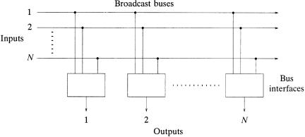
The knockout switch w28x is illustrated in Figure 6.1. It is composed of a completely broadcasting interconnection fabric and N bus interfaces. The interconnection fabric for the knockout switch has two basic characteristics: Ž1. each input has a separate broadcast bus, and Ž2. each output has access to all broadcast buses and thus all input cells.
With each input having a direct path to every output, no switch blocking occurs within the interconnection fabric. The only congestion in the switch takes place at the interface to each output, where cells can arrive simultaneously on different inputs destined for the same output. The switch architecture is modular in that the N broadcast buses can reside on an equipment backplane with the circuitry for each of the N input output pairs placed on a single plug-in circuit card.
Fig. 6.1 Knockout switch interconnection fabric.
SINGLE-STAGE KNOCKOUT SWITCH |
143 |
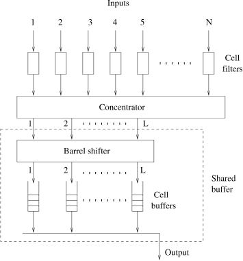
Fig. 6.2 Knockout switch bus interface. Ž 1987 IEEE..
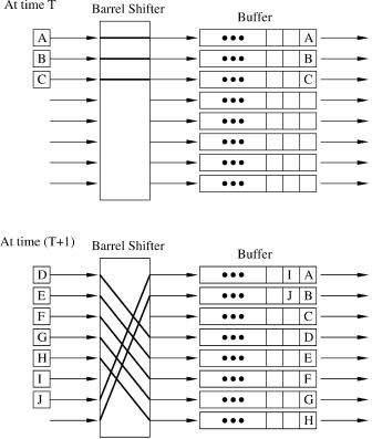
Figure 6.2 illustrates the architecture of the bus interface associated with each output of the switch. The bus interface has three major components. At the top there are a row of N cell filters where the address of every cell is examined, with cells addressed to the output allowed to pass on to the concentrator and all others blocked. The concentrator then achieves an N-to-L Ž L N . concentration of the input lines, and up to L cells in each time slot will emerge at outputs of the concentrator. These L concentrator outputs then enter a shared buffer, which is composed of a barrel shifter and L separate FIFO buffers. The shared buffer allows complete sharing of the L FIFO buffers and provides the equivalent of a single queue with L inputs and one output, each operated under a FIFO queuing discipline. The operation of the barrel shifter is shown in Figure 6.3. At time T, cells A, B, C arrive and are stored in the top three FIFO buffers. At time T q 1, cells D to J arrive and begin to be stored from the fourth FIFO in a round-robin manner. The number of positions that the barrel shifter shifts is equal to the sum of arriving cells mod L.
144 KNOCKOUT-BASED SWITCHES
Fig. 6.3 Operation of a barrel shifter.
6.1.2 Knockout Concentration Principle
All cells passing through the cell filters enter the concentrator, with an N-to-L concentration. If there are k F L cells arriving in a time slot for a given output, these k cells will emerge from the concentrator on outputs 1 to k after getting out of the concentrator. If k L, then all L outputs of the concentrator will have cells, and k y L cells will be dropped Ži.e., lost. within the concentrator.
The cell loss probability is evaluated as follows. It is assumed that, in every time slot, there is a fixed and independent probability that a cell arrives at an input. Every cell is equally likely destined for each output. Denote by Pk the probability of k cells arriving in a time slot all destined for the same output, which is binomially distributed as follows:
Pk s žNk /ž |
|
/k ž1 y |
|
/Nyk , k s 0, 1, . . . , N. |
Ž6.1. |
N |
N |
SINGLE-STAGE KNOCKOUT SWITCH |
145 |
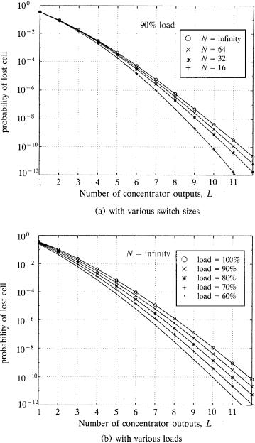
Fig. 6.4 Concentrator cell loss performance.
146 KNOCKOUT-BASED SWITCHES
It then follows that the probability of a cell being dropped in a concentrator with N inputs and L outputs is given by
|
|
ksLq1 |
|
|
|
ž k / |
|
|
ž N / |
|
ž |
|
|
|
N |
/ |
|
|
|
|
1 |
N |
|
|
|
N |
|
|
|
|
k |
|
|
|
|
|
|
Nyk |
|
Prwcell lossx s |
|
Ý |
Ž k y L. |
|
|
|
|
|
|
1 y |
|
|
|
. Ž6.2. |
|||||
Taking the limit as N ™ , and with some manipulations, |
|
|
|
|
|
||||||||||||||
|
|
|
|
L |
L k ey |
|
|
|
|
Ley |
|
|
|||||||
Prwcell lossx s ž1 y |
|
|
/ž1 y kÝs0 |
|
|
|
/ |
q |
|
|
|
|
Ž6.3. |
||||||
|
|
|
|
k! |
|
L! |
|
|
|||||||||||
Using Ž6.2. and Ž6.3., Figure 6.4Ža. shows a plot of the cell loss probability versus L, the number of outputs on the concentrator, for s 0.9 and N s 16, 32, 64, . Note that a concentrator with only eight outputs achieves a cell loss probability less than 10y6 for arbitrately large N. This is comparable to the probability of losing a 500-bit cell from transmission errors with a bit error rate of 10y9 . Also note from Figure 6.4Ža. that each additional output added to the concentrator beyond eight results in an order of magnitude decrease in the cell loss probability. Hence, independent of the number of inputs Ž N ., a concentrator with 12 outputs will have a cell loss probability less than 10y10 . Figure 6.4Žb. illustrates, for N ™ , that the required number of concentrator outputs is not particularly sensitive to the load on the switch, up to and including a load of 100%. It is also important to note that, assuming independent cell arrivals on each input, the simple, homogeneous model used in the analysis corresponds to the worst case, making the cell loss probability performance results shown in Figure 6.4 upper bounds on any set of heterogeneous arrival statistics w10x.
6.1.3 Construction of the Concentrator
The basic building block of the concentrator is a simple 2 2 contention switch shown in Figure 6.5Ža.. The two inputs contend for the winner output according to their activity bits. If only one input has an arriving cell Žindicated by an activity bit s 1., it is routed to the winner Žleft. output. If both inputs have arriving cells, one input is routed to the winner output and the other input to the loser output. If both inputs have no arriving cells, we do not care, except that the activity bit for both should remain at logic 0 at the switch outputs.
The above requirements are met by a switch with the two states shown in Figure 6.5Žb.. The switch examines the activity bit of the left input only. If the activity bit is a 1, the left input is routed to the winner output and the right input is routed to the loser output. If the activity bit is a 0, the right input is routed to the winner output, and no path is provided through the switch for the left input. Such a switch can be realized with as few as 16 gates, and