

Broadband Packet Switching Technologies
.pdf228 CROSSPOINT BUFFERED SWITCHES
Fig. 8.1 Crosspoint-buffered switch structure based on round-robin arbitration.
8.1 OVERVIEW OF CROSSPOINT-BUFFERED SWITCHES
A basic crosspoint-buffered switch architecture is shown in Figure 8.1. Each crosspoint has a buffer to store cells that come from the associated input port and are destined for the associated output port.
Contention control is needed to resolve contention among crosspoint buffers that belong to the same output port. One candidate for the contention control is to use round-robin ŽRR. arbitration. This is because the RR arbitration provides fairness and its implementation is very simple.
The RR arbiter searches, from some starting point, for a crosspoint buffer that has made a request to transfer a cell to the output line. The starting point is just below the crosspoint buffer from which a cell was sent to the output line at the previous cell time. If the RR arbiter finds the request, the cell at the head in the crosspoint buffer is selected to release its cell. At the next cell time, the starting point is reset to just below the selected crosspoint buffer. Thus, in the worst case, the control signal for ring arbitration must pass through all the crosspoint buffers belonging to the same output line within one cell time.
For that reason, in the buffered crossbar that employs RR arbitration for the contention control, the maximum output-line speed is limited by the number of input ports, or switch size, and the transmission delay of the control signals in each crosspoint.
The maximum output-line speed Cmax Žbitsrs. is given by the following
equation: |
|
|
|
|
|
Cmax |
s |
L |
, |
Ž8.1. |
|
NTs |
|||||
|
|
|
|
where the number of input ports Žin other word, the switch size. is N, the transmission delay of the control signals in a crosspoint is Ts Žs., and the
SCALABLE DISTRIBUTED-ARBITRATION SWITCH |
229 |
length of a cell is L Žbits.. Ts depends on the performance of devices and the length between crosspoints. When we construct a large-scale switch, its crossbar function can not be implemented on one chip, due to constraints from memory and gate amounts and the number of IrO pins. Therefore, we need to connect several chips to construct a large-scale switch.
As N increases, Cmax decreases. For example, at Ts s 3.0 ns and N s 16, Cmax is 8.8 Gbitrs, when we set L to 53 8 bits. Thus, since the crosspointbuffered switch employs RR arbitration, the arbitration time limits the
output-line speed according to the number of input ports to ensure that the RR arbitration can be completed within one cell time. As a result, unless Ts is made small by using ultrahigh-speed devices, the RR based switch cannot achieve large throughput.
8.2 SCALABLE DISTRIBUTED-ARBITRATION SWITCH
This section describes a scalable distributed-arbitration ŽSDA. switch, to solve the problem of the RR based switch as described Section 8.1. The SDA switch was developed by Nippon Telegraph and Telephone Corporation ŽNTT. w2x.
8.2.1 SDA Structure
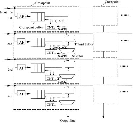
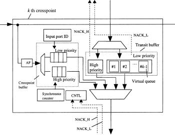
Figure 8.2 shows the structure of the SDA switch. The SDA switch has a crosspoint buffer, a transit buffer, an arbitration-control part ŽCNTL., and a selector at every crosspoint.
A crosspoint buffer sends a request ŽREQ. to CNTL if there is at least one cell stored in the crosspoint buffer. A transit buffer stores several cells that are sent from either the upper crosspoint buffer or the upper transit buffer. The transit buffer size is one or a few cells, so that both overflow and underflow can be avoided. The required transit buffer size is determined by the round-trip delay of control signals between two adjacent crosspoints. The transit buffer sends REQ to CNTL, as does the crosspoint buffer, if there is at least one cell stored in the transit buffer. If the transit buffer is full, it sends not-acknowledgment ŽNACK. to the upper CNTL.
If there are any REQs and CNTL does not receive NACK from the next lower transit buffer, CNTL selects a cell within one cell time. CNTL determines which cell should be sent according to the following cell selection rule. The selected cell is sent through a selector to the next lower transit buffer or the output line.
The rule selects a cell as follows. If either the crosspoint buffer or the transit buffer requests cell release, the cell in the requesting buffer is selected. If both the crosspoint buffer and the transit buffer request cell release, the cell with the larger delay time is selected. The delay time is defined as the time since the cell entered the crosspoint buffer.
230 CROSSPOINT BUFFERED SWITCHES
Fig. 8.2 Scalable distributed-arbitration switch structure. Ž 1997 IEEE..
One way of comparing the delay time of competitive cells is to use asynchronous counter, which needs S bits, and also the same overhead bit in each cell. The synchronous counter is incremented by one in each cell time. All the synchronous counter’s values are synchronized. When a cell enters a crosspoint buffer, the value of the synchronous counter is written in the overhead of the cell. When both a crosspoint buffer and a transit buffer issue requests for cell release, the values of both counters are compared. If the difference in values is more than 2 Sy1 , the cell with smaller value is selected. To the contrary, if the difference is equal to or less than 2 Sy1 , the cell with larger value is selected. Under the condition that the maximum delay time is less than 2 Sy1 , this delay-time comparison works. As will be explained in the next section, S s 8 is sufficiently large in the SDA switch.
When the delay time of the cell in the crosspoint buffer equals that in the transit buffer, CNTL determines which cell should be sent using the second cell selection rule. Let us consider the k th crosspoint and transit buffers
SCALABLE DISTRIBUTED-ARBITRATION SWITCH |
231 |
counting from the top. The second rule is that the k th crosspoint buffer is selected with probability 1rk, while the k th transit buffer is selected with probability of Žk y 1.rk. For example, the third crosspoint buffer and the transit buffer are selected with probabilities 13 and 23 , respectively.
Thus the SDA switch achieves distributed arbitration at each crosspoint. The longest control signal transmission distance for arbitration within one cell time is obviously the distance between two adjacent crosspoints. In the conventional switch, the control signal for ring arbitration must pass through all crosspoint buffers, belonging to the same output line. For that reason, the arbitration time of the SDA switch does not depend on the number of input ports.
8.2.2 Performance of SDA Switch
SDA switch performance was evaluated in terms of delay time and crosspoint buffer size by computer simulation. It is assumed that, in an N N cross- point-buffered switch, the input traffic is random, the input load is 0.95, and cells are distributed uniformly to all crosspoint buffers belonging to the same input line.
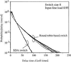
The SDA switch ensures delay time fairness. Figure 8.3 shows the probability of the delay time being larger than d at N s 8. The probability is shown for each crosspoint buffer entered by cells. The delay time is defined as the time from the cell’s entering the crosspoint buffer until it reaches the
Fig. 8.3 Delay performance of SDA switch. Ž 1997 IEEE..
232 CROSSPOINT BUFFERED SWITCHES
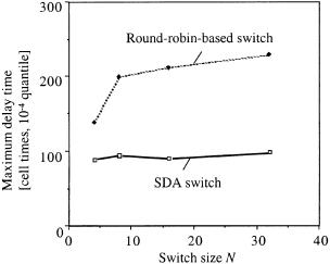
Fig. 8.4 Maximum delay time. Ž 1997 IEEE..
output line. In the SDA switch, when d is more than about 10 cell times, all delay times have basically the same probability and delay time fairness is achieved. ŽSince it takes at least N s 8 cell times for the cell in the top crosspoint buffer to enter the output line, fairness is not maintained at smaller values..
In addition, when d is larger than a certain time, the probability of the SDA switch delay time being larger than d is smaller than that of the RR switch, as shown in Figure 8.3. This is because, in the SDA switch, the cell with the largest delay time is selected.
This effect becomes clearer as N increases. Figure 8.4 shows that the maximum delay time Ž10y4 quantile. of the SDA does not change very much when N increases, while that of the RR switch increases rapidly. Furthermore, maximum SDA delay is smaller than 27 Žs 128. cell times even at large N. This means that synchronous counter size is just S s 8, as mentioned before.
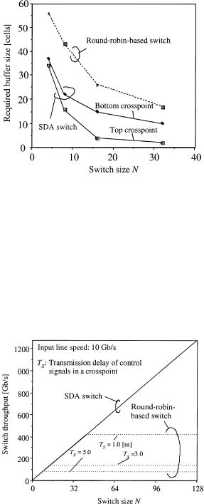
The required crosspoint buffer size of the SDA switch is smaller than that of the switch, as shown in Figure 8.5. The required buffer sizes were estimated so as to guarantee the cell loss ratio of 10y9. In the SDA switch, since the required buffer sizes differ for the crosspoint buffers, Figure 8.5 shows the smallest Žtop crosspoint buffer. and the largest Žbottom crosspoint buffer. sizes. The sizes of the intermediate crosspoint buffers lie between these two values. Because the SDA switch has shorter delay time as explained before, the queue length of the crosspoint buffer is also reduced. This is why the crosspoint buffer size of the SDA switch is less than that of the RR switch.
The switch throughput of the SDA switch increases as the switch size N increases, as shown in Figure 8.6. Since the arbitration time does not limit
SCALABLE DISTRIBUTED-ARBITRATION SWITCH |
233 |
Fig. 8.5 Required buffer size. Ž 1997 IEEE..
the output-line speed, the SDA switch can be expanded to achieve high switch throughput even if N is large. The switch throughput is calculated as Cmax N, where Cmax is the maximum output line speed.
On the other hand, the switch throughput of the RR-based switch does not increase when N becomes large. Instead it depends on the transmission delay of the control signal in a crosspoint. The RR arbitration time limits the output line speed. The RR-based switch is not expandable, because of the limitation of the RR arbitration time.
Fig. 8.6 Switch throughput vs. switch size. Ž 1997 IEEE..
234 CROSSPOINT BUFFERED SWITCHES
8.3 MULTIPLE-QOS SDA SWITCH
Section 8.2 describes an SDA switch, that can support a single QoS class. This section describes a multiple-QoS SDA ŽMSDA., to support multiple QoS classes by extending the concept of the SDA switch. The MSDA switch was presented in w4, 5x. We call the single-QoS SDA switch described in Section 8.2 SSDA in order to differentiate it from MSDA.
To support multiple QoS classes, a priority queuing control at each crosspoint buffer is needed. One priority queuing approach is strict priority control. Consider two priority buffers. Under the strict priority system, cells waiting in the low-priority buffer Ždelay-tolerant. are served only if there are no cells awaiting transmission in the high-priority Ždelay-sensitive. buffer. Therefore, in the strict priority discipline, the low-priority traffic effectively uses the residual bandwidth.
However, a problem occurs when we use a SSDA mechanism in a strict priority system that supports multiple QoS classes. The delay time of cells in the low-priority buffer will be very large, and the maximum delay time cannot be designed. Therefore, we cannot use the delay-time-based cell selection mechanism, as is used in the SSDA switch, for the low-priority class, due to the limitation on the number of bits for the delay measure in the cell header.
The MSDA switch was developed to support highand low-priority classes. In order to solve the problem of a cell selection mechanism for the low-prior- ity class, NTT introduced a distributed RR-based cell selection mechanism at each crosspoint for the low-priority class, which avoids using a synchronous counter such as is used for the high-priority class w4, 5x. The low-priority transit buffer at each crosspoint has virtual queues in accordance with the upper input ports. Cells for the low-priority class are selected by distributed ring arbitration among the low-priority crosspoint buffer and the virtual queues at the low-priority transit buffer. For the high-priority class, the same delay-time-based cell selection mechanism is used as in the SSDA switch. As a result, the proposed MSDA switch ensures fairness in terms of delay time for the high-priority class, while it ensures fairness in terms of throughput for the low-priority class.
8.3.1 MSDA Structure
This subsection describes the structure of the MSDA switch. Although we describe two priority classes in this paper for simplicity, we can easily extend the number of priority classes to more than two.
The low-priority class tolerates delay, while the high-priority class requires a small delay time. In addition, the low-priority class is supposed to be a best-effort service class such as the unspecified bit rate ŽUBR. class. It requires fairness in terms of throughput rather than in terms of delay time, in order to effectively use the residual bandwidth that is not used by the high-priority traffic. Therefore, it needs a cell selection mechanism that
MULTIPLE-QOS SDA SWITCH |
235 |
Fig. 8.7 Multi-QoS SDA ŽMSDA. switch structure. Ž 1999 IEEE..
preserves fairness in terms of delay time for the high-priority buffer and in terms of throughput for the low-priority class.
In order to avoid the delay-time-based cell selection mechanism for the low-priority class, a distributed RR-based cell selection mechanism at each crosspoint for the low-priority class is used.
Figure 8.7 shows the structure of the MSDA switch at the k th crosspoint. The MSDA switch has a crosspoint buffer and a transit buffer, each consisting of a high-priority buffer and a low-priority buffer, an arbitration-control part ŽCNTL., and a selector at every crosspoint.
A cell that passes an address filter ŽAF. enters into either the highor the low-priority crosspoint buffer according to its priority class. At that time, at the high-priority crosspoint buffer, the value of a synchronous counter is written into the cell overhead, as in the SSDA switch. On the other hand, at the low-priority buffer, an input port identifier ŽID. is written. For example, at the k th crosspoint, the value of the input port ID is k. This is used to distinguish which input port a cell comes from. The highand low-priority crosspoint buffers send REQ to CNTL if there is at least one cell stored in each buffer.
A cell that is transmitted from the upper crosspoint enters either the high-priority transit buffer or the low-priority crosspoint buffer according to the priority class. The low-priority transit buffer has k y 1 virtual queues, which are numbered 1, 2, . . . , k y 1. A low-priority cell that has input port ID i Ž1 F i F k y 1. enters virtual queue i. The high-priority transit buffer and the low-priority transit virtual queues send REQ to CNTL if there is at
236 CROSSPOINT BUFFERED SWITCHES
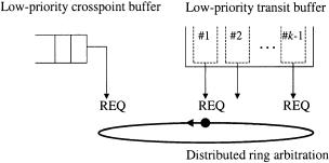
Fig. 8.8 Low-priority selection rule. Ž 1999 IEEE..
least one cell stored in each buffer or virtual queue. If the highor low-priority transit buffers are about to become full, they send not-acknowl- edgments NACK H and NACK L, respectively, to the upper CNTL.
The cell selection algorithm in the MSDA switch is as follows. If CNTL receives NACK dH from the lower high-priority transit buffer, neither a high-priority cell nor a low-priority cell is transmitted. This is because, when the lower high-priority transit buffer is about to become full, there is no chance for the low-priority cell in the lower transit buffer to be transmitted. Low-priority cells cannot be transmitted when there is at least one high-prior- ity REQ from the crosspoint buffer and the transit buffer. When both the high-priority crosspoint buffer and the high-priority transit buffer send REQs to CNTL, the high-priority cell selection rule used is the cell selection rule used in the SSDA switch.
Low-priority cells can be transmitted only when there are no REQs from either the high-priority crosspoint buffer or the high-priority transit buffer. If this condition is satisfied and CNTL does not receive either NACK H or NACK L from the lower transit buffer, then the low-priority selection rule is used. The low-priority crosspoint buffer and virtual queues in the low-priority transit buffer send REQs to CNTL as shown in Figure 8.8. Ring arbitration is executed at each crosspoint in a distributed manner. CNTL selects a cell and transmits it to the lower transit buffer.
Thus the MSDA switch achieves distributed arbitration at each crosspoint. It uses the delay-time-based cell selection rule for the high-priority buffer and the distributed RR-based cell selection rule for the low-priority class.
8.3.2 Performance of MSDA Switch
The performance of the MSDA switch is described. It is assumed that, in an N N crosspoint-buffered switch, input traffic for both the highand lowpriority classes is random, and cells are distributed uniformly to all crosspoint buffers belonging to the same input line.
|
|
|
|
MULTIPLE-QOS SDA SWITCH |
237 |
||||
TABLE 8.1 Throughput in MSDA Switch (Case 1) |
|
|
|
|
|||||
|
|
|
|
|
|
|
|
||
Inport |
|
Input Load |
|
Throughput |
|
||||
|
|
|
|
|
|
|
|
|
|
Port |
|
High |
Low |
|
High |
Low |
|
||
|
|
|
|
|
|
|
|
||
1 |
0.060 |
0.050 |
0.060 |
0.050 |
|
|
|
||
2 |
0.060 |
0.050 |
0.060 |
0.050 |
|
|
|
||
3 |
0.060 |
0.150 |
0.060 |
0.050 |
|
|
|
||
4 |
0.180 |
0.050 |
0.180 |
0.050 |
|
|
|
||
5 |
0.060 |
0.050 |
0.060 |
0.050 |
|
|
|
||
6 |
0.060 |
0.050 |
0.060 |
0.050 |
|
|
|
||
7 |
0.060 |
0.050 |
0.060 |
0.050 |
|
|
|
||
8 |
0.060 |
0.050 |
0.060 |
0.050 |
|
|
|
||
|
|
|
|
|
|
|
|
||
Total |
0.600 |
0.500 |
0.600 |
0.400 |
|
|
|
||
|
|
|
|
|
|
|
|
||
TABLE 8.2 Throughput in MSDA Switch (Case 2) |
|
|
|
|
|||||
|
|
|
|
|
|
|
|||
Inport |
|
Input Load |
|
Throughput |
|
||||
|
|
|
|
|
|
|
|
|
|
Port |
|
High |
Low |
|
High |
Low |
|
||
|
|
|
|
|
|
|
|
||
1 |
0.060 |
0.030 |
0.060 |
0.030 |
|
|
|
||
2 |
0.060 |
0.030 |
0.060 |
0.030 |
|
|
|
||
3 |
0.060 |
0.400 |
0.060 |
0.190 |
|
|
|
||
4 |
0.180 |
0.030 |
0.180 |
0.030 |
|
|
|
||
5 |
0.060 |
0.030 |
0.060 |
0.030 |
|
|
|
||
6 |
0.060 |
0.030 |
0.060 |
0.030 |
|
|
|
||
7 |
0.060 |
0.030 |
0.060 |
0.030 |
|
|
|
||
8 |
0.060 |
0.030 |
0.060 |
0.030 |
|
|
|
||
|
|
|
|
|
|
|
|
||
Total |
0.600 |
0.600 |
0.600 |
0.400 |
|
|
|
||
|
|
|
|
|
|
|
|
|
|
Since the high-priority is not influenced by, but does influence the low-pri- ority class, the results of the high-priority class are the same as those of the SSDA switch. Therefore, only the performance for the low-priority buffer is presented here.
Tables 8.1 and 8.2 show that the MSDA switch keeps the fairness in terms of the throughput for the low-priority class. We present results for two traffic conditions, case 1 and case 2. The switch size was set to N s 8.
In case 1, the high-priority load of the fourth input port is 0.18 and that of other input ports is 0.06. The low-priority load of the third input port is 0.15 and that of other input ports is 0.05, as shown in Table 8.1. The total input load is 1.1 Ž0.6 q 0.5., which is overloaded. The output load, which we call the throughput, for the high-priority class is the same as the high-priority input load for each input port. The low-priority throughput of all input ports is equally divided into 0.05 to utilize the residual bandwidth. Thus, the residual bandwidth is fairly shared with all the low-priority input traffic, although its requests for bandwidth are different.