

Neutron Scattering in Biology - Fitter Gutberlet and Katsaras
.pdf11 Complex Biological Structures |
223 |
56.G.E. Bacon, Neutron Anatomy, in: Neutrons in Biology, ed. by B.P. Schoenborn, R. Knott (Plenum Press, New York, 1996), pp. 17–27
57.A. Guinier, G. Fournet, in: Small-angle Scattering of X-rays (Wiley, New York, 1955)
58.O. Glatter, O. Kratky, in: Small-angle X-ray scattering (Academic Press, New York, 1983)
59.P. Fratzl, J. Appl. Cryst. 36, 397–404 (2003)
60.P. Fratzl, N. Fratzl-Zelman, K. Klaushofer et al, Calcif. Tissue Int. 48, 407–413 (1991)
61.P. Fratzl, S. Schreiber, K. Klaushofer, Conn. Tissue Res. 35, 9–16 (1996)
62.P. Fratzl, H.F. Jakob, S. Rinnerthaler et al, J. Appl. Cryst. 30, 765–769 (1997)
63.S. Rinnerthaler, P. Roschger, H.F. Jakob et al, Calcif. Tissue Int. 64, 422–429 (1999)
64.O. Paris, I. Zizak, H. Lichtenegger et al, Cell Mol. Biol. 46, 993–1004 (2000)
65.P. Roschger, B.M. Grabner, S. Rinnerthaler et al, J. Struct. Biol. 136, 126–136 (2001)
66.P. Roschger, H.S. Gupta, A. Berzanovich et al, Bone 32, 316–323 (2003)
67.W. Tesch, N. Eidelman, P. Roschger et al, Calcif. Tissue Int. 69, 147–157 (2001)
68.H.S. Gupta, P. Roschger, I. Zizak et al, Calcif. Tissue Int. 72, 567–576 (2003)
69.I. Zizak, P. Roschger, O. Paris et al, J. Struct. Biol. 141, 208–217 (2003)
70.P. Fratzl, P. Roschger, J. Eschberger et al, J. Bone Miner. Res. 9, 1541–1549 (1994)
71.P. Fratzl, O. Paris, K. Klaushofer et al, J. Clin. Invest. 97, 396–402 (1996)
72.P. Fratzl, S. Schreiber, P. Roschger et al, J. Bone Miner. Res. 11, 248–253 (1996)
73.P. Roschger, P. Fratzl, K. Klaushofer et al, Bone 20, 393–397 (1997)
74.B. Grabner, W. J. Landis, P. Roschger et al, Bone 29, 453–457 (2001)
75.P. Roschger, S. Rinnerthaler, J. Yates et al, Bone 29, 185–191 (2001)
76.B.M. Misof, P. Roschger, W. Tesch et al, Calcif. Tissue Int. 73, 251–257 (2003)
77.W. Tesch, T. Vandenbos, P. Roschger et al, J. Bone Miner. Res. 18, 117–125 (2003)
78.O. Paris, D. Loidl, H. Peterlik et al, J. Appl. Cryst. 33, 695–699 (2000)
79.C. Riekel, Rep. Prog. Phys. 63, 233–262 (2000)
80.I. Zizak, O. Paris, P. Roschger et al, J. Appl. Cryst. 33, 820–823 (2000)
81.N.P. Camacho, S. Rinnerthaler, E.P. Paschalis et al, Bone 25, 287–293 (1999)
82.P. Roschger, P. Fratzl, J. Eschberger et al, Bone 23, 319–326 (1998)
83.A. Boyde, S.J. Jones, Microscopy Res. Tech. 33, 92–120 (1996)
84.T.J. Wess, M. Drakopoulos, A. Snigirev et al, Archaeometry 43, 117–129 (2001)
85.A. Cedola, V. Stanic, M. Burghammer et al, J. Phys. IV 104, 329–332 (2003)
86.H.R. Wenk, F. Heidelbach, Bone 24, 361–369 (1999)
87.F. Heidelbach, C. Riekel, H.R. Wenk, J. Appl. Cryst. 32, 841–849 (1999)
88.V.A. Sharov, Q.-F. Xiao, I. Ponomarev et al, Rev. Sci. Instrum. 71, 3247–3253 (2000)
89.H.R. Beguiristain, I.S. Anderson, C.D. Dewhurst et al, Appl. Phys. Lett. 81, 4290–4292 (2002)
90.H.M. Shimizu, Y. Suda, T. Oku et al, Nuclear Instrum. Methods Phys. Res. A 430, 423–434 (1999)
91.F. Pfei er, V. Leiner, P. Hoghoj et al, Phys. Rev. Lett. 88, 055507-1-4 (2002)

12
Structural Investigations of Membranes in Biology by Neutron Reflectometry
C.F. Majkrzak, N.F. Berk, S. Krueger, U.A. Perez–Salas
12.1 Introduction
Membranes are an essential part of every living cell. Determining the nanometer scale structure of these partitions is of interest for the understanding of important cellular processes on a molecular level, including, for example, transport mechanisms into and out of the cell interior and the functioning of protein sensors embedded in the membrane [1].
In “real” space, probes such as atomic force and electron microscopies, at present, can provide localized images of a material surface with nanometer scale resolution. However, scattering techniques employing neutrons and X-rays have proven to be especially well-suited for “viewing”, in comparable detail, the distribution of matter beneath the surface. The reasons for this subsurface sensitivity are manifold, but principally are a consequence of the wave nature of the radiation, the relative strengths of interaction (between photon and atomic electrons or between neutron and nucleus), and the ability to accurately measure and analyze the di raction pattern that the material density distribution of the film gives rise to.
The sensitivity of di raction as a probe of membrane structure is considerably enhanced if a homogeneous specimen of the film can be constrained to lie on a flat surface (either a solid or liquid substrate). A membrane so confined is, e ectively, a quasi two-dimensional scattering object. Treating the neutron as a plane wave, having a wavevector k proportional to its momentum, the coherent (in phase), elastic (no energy transfer) reflection of that neutron from a flat film can be then separated into two distinct types, specular and non-specular. Specular scattering refers to the condition in which the glancing angle θ between the reflected neutron wavevector and the surface is equal to that of the incident wave. In this case the momentum transfer is exactly perpendicular to the surface. Analysis of the specular reflectivity reveals the depth profile of the film’s density along the surface normal. If there are no variations in the composition or material density within the plane of the film, then only specular scattering can occur. In a case where
226 C.F. Majkrzak et al.
in-plane fluctuations of the density are present, the specular component of the reflected intensity is caused by a film density that is averaged, at a given depth, over the in-plane area for which the neutron plane wavefront is coherent (typically of the order of microns). In addition, however, in-plane fluctuations produce non-specular scattering wherein the momentum transfer has a component parallel to the surface. Non-specular scattering data thus contains information about in-plane structure. Non-specular reflectometry has great potential for the study of biofilms, for example, in determining the sizes and distribution of various entities, such as cholesterol “rafts”, within the plane of a membrane. However, research in this area is not yet as developed as that involving specular reflectometry. The reasons for this involve a number of technical di culties, including the preparation of specimens of su cient size and homogeneity and the theoretical interpretation of the non-specular scattering, particularly at wavevector transfers where the Born approximation (discussed below) is not valid. The present chapter is concerned primarily with specular reflection. The interested reader is referred elsewhere for discussions of non-specular scattering, e.g., [2, 3].
The resolution of a material distribution in real space deduced from diffraction data is, ultimately, inversely proportional to the range in wavevector transfer Q over which the reflected intensity is measured. The wavevector transfer for the reflected beam is kf −ki = −2k sin(θ) = −4π sin(θ)/λ = −2k0z , where k0z is the component of the incident wavevector normal to the film. We will always define Q = 2k0z , so that the reflected wavevector transfer is −Q. For instance, the spatial resolution in the compositional depth profile obtained from analysis of the specular reflectivity (defined as the reflected intensity divided by the incident intensity) measured out to a wavevector transfer of 0.7 ˚A−1 corresponds to a spatial resolution of the order of 0.5 nm. Given the strength of available neutron sources, sample areas of several square millimeters or more are therefore necessary in practice to obtain su ciently accurate data. Reflectivity experiments (i.e., “reflectometry”) conducted over a range of wavevector transfers similar to that just given are to be distinguished from di raction studies performed at higher wavevector transfers corresponding to interatomic scale resolution.
The purpose of this contribution is to provide an overview of the experimental and theoretical methods now employed in the study of membrane structures by specular neutron reflectometry. Nonetheless, a reasonable amount of detail is included here so that the researcher new to the technique can better judge what structural information is obtainable from reflectometry and can assess what actually is required to prepare a suitable specimen, perform measurements, and subsequently analyze the data. Reviews of current research in which neutron reflectometry has been applied to the study of biological or biomimetic membrane structures, including systems with embedded proteins and peptides, are given in other contributions of this volume by Lu, Gutberlet et al., Salditt et al., and elsewhere [4]. However, a representative example of a neutron reflectometry study of a lipid bilayer membrane into

12 Membranes in Biology by Neutron Reflectometry |
227 |
which the peptide melittin has been introduced is included here, to further illustrate the technique.
12.2 Theory
The theory of neutron reflectivity and di raction is well-established [5–10], although there have been relatively recent developments in methods for phase determination and inversion (see, for example, the review [11] and references therein). This section summarizes key features of the theory pertinent to the study of thin films and membranes.
12.2.1 The Exact (“Dynamical”) Solution
The specular reflectivity from a flat surface or film e ectively reduces to a one-dimensional wave mechanics problem (see Merzbacher [13], for example)
− |
∂2ψ(z) |
+ 4πρ(z)ψ(z) = k02z ψ(z) , |
(12.1) |
∂z2 |
where k0z is the wavevector of the neutron in vacuum and ρ(z) is the the scattering length density (SLD) “profile,” which describes the neutron interaction with the film and its surrounding media everywhere along the z-axis, normal to the film surface. For neutrons with wavelengths of the order of several ˚Angstroms, the SLD at any “point” is the compositionally weighted average of the coherent neutron scattering lengths in a volume element having linear dimensions on the order of the neutron wavelength, divided by the volume of the element. Scattering length densities thus have dimensions of inverse area. Scattering lengths are the fundamental measure of the neutron–nucleus interaction and vary from one isotope to another in an essentially random but fixed manner. Coherent, in this context, refers to the component of the interaction that enables neutrons scattered by nuclei at di erent points in the film to interfere, much as ripples on a pond. It is such interference which makes the scattering dependent on spatial structure.
We have assumed the ideal situation for specular scattering where the SLD varies only along the surface normal. In general the SLD ρ(x, y, z) can vary in all three directions in the film, so that the true reflection problem is inherently three-dimensional. Thus, the SLD ρ(z) appearing in Eq. 12.1 is defined as
ρ(z) = lim 1 (12.2)
S→∞ S
S
where S denotes the surface area of the film. In-plane variations of the SLD give rise to non-specular scattering. In the most extreme case, the specular reflection caused by ρ(z) and the non-specular reflection caused by ∆ρ(x, y, z)
228 C.F. Majkrzak et al.
interfere with one another, so that the resultant reflectivity cannot be expressed as two distinct contributions. However, in many cases of interest, either the non-specular component is negligible or the two contributions are separable. When lateral variations of the SLD are random, the measured reflectivity represents a “thermodynamic” average of the reflectivity over a suitable ensemble of such configurations. For cases where ρ(x, y, z) is “self–
averaging,” i.e., where ρ(x, y, z) xy = ρ(x, y, z) therm, it can be shown that the specular reflection determined by ρ(z) and the non-specular reflection in-
duced by the residual ∆ρ(x, y, z) are decoupled from one another [14]. Even then, however, we need to know how to separate them. The specular reflectivity is defined as the ratio of the specularly reflected intensity to the incident intensity; the non-specular intensity a ects both. When the instrument is configured to collect the specular signal (i.e., on the specular ridge), some fraction of the non-specular intensity is also counted and, therefore, must be subtracted. At the same time, non-specular intensity in other directions diminishes incident intensity which would otherwise cause specular reflection.
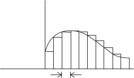
For both computational and analytic purposes, an SLD profile ρ(z) of any shape can be accurately represented, for measurements up to a finite maximum Q = Qmax, by a piecewise continuous subdivision, ρpwc(z), into a su cient number of rectangular slices, or “bins”’ of widths ∆z π/Qmax, where the SLD within each slice is taken to be constant, as depicted schematically in Fig. 12.1. The fundamental quantity describing the specular reflection of the neutron by the membrane is the spectrum (as a function of Q) of the reflection amplitude r, a complex number, r = |r|eiφ of modulus |r| and a phase φ. Similarly, the transmitted wave is characterized by a transmission amplitude t, but it turns out that all of the relevant information is contained in the
r
z
z
Fig. 12.1. Scattering length density depth profile, along the surface normal, of arbitrary shape represented by rectangular bins or slices over each of which the density is taken to be constant

12 Membranes in Biology by Neutron Reflectometry |
229 |
spectrum of r. To set up equations which describe the relationship between r, t, and ρ, we first make the piecewise continuous rendering of ρ(z) explicit with
ρj if (j − 1)∆z ≤ z < j∆z,
ρpwc(z) = (12.3)
0otherwise,
where j = 1, ··· , N . Thus ρpwc(z) is a “histogram” of N bins of uniform width ∆z = L/N , where ρpwc(z) = ρj in the jth bin. Next, we partition the z-axis (along the film normal) into three contiguous regions: region I, the “fronting,” where z < 0; region II, the “film of interest,” where 0 ≤ z ≤ L; and region III, the “backing,” where z > L. The fronting is defined as the region containing the incident and reflected beams, while the backing is the
region of the transmitted beam, regardless of how the film is mechanically supported. In region I, ρ(z) = ρI, and in region III, ρ(z) = ρIII, where ρI
and ρIII are known constants (typically, the SLD values for air or vacuum, silicon, sapphire, and mixtures of water and heavy water, as appropriate to the experiment). With each of the regions of constant SLD, viz., I and III and in the slabs comprising ρpwc in II, we can associate a wavevector component along the z-axis
kzI,II,III = k0z 1 − 4πρI,II,III/k02z ≡ nIz,II,IIIk0z . (12.4)
(From now on we will suppress the “z” subscript on k.) Note that in region II, where ρ = ρpwc has values ρj , kzII has the corresponding values kjII. In regions I and III, the physical solutions of Eq. 12.1 have the simple plane wave forms
eikIz + re |
|
ikIz |
for z < 0, |
|
ψI,III(z) = teikIIIz |
− |
|
for z > L. |
(12.5) |
These solutions (and their derivatives) are “transferred” across region II by the matrix equation [11, 15],
t |
III |
1 + r |
|
inIIIt eik |
|
L = M inI(1 − r) , |
(12.6) |
A B
where the transfer matrix M = is a 2 × 2 real-valued matrix having
C D
unit determinant, AD − BC = 1. For ρpwc, this is the matrix product
M = MN MN −1, ··· , Mj , ··· , M2M1 , |
(12.7) |
|||
where Mj is the transfer matrix for the jth bin, |
|
|
|
|
cos(kII∆z) |
sin(kII∆z)/nII |
. |
|
|
j |
j |
j |
|
|
Mj = −njII sin(kjII∆z) |
cos(kjII∆z) |
|
(12.8) |
|

230 C.F. Majkrzak et al.
In general Eq. 12.7 can represent any useful decomposition of ρ(z) into N contiguous, non-overlapping segments.
Equation 12.6 stands for two simultaneous linear equations, which are straightforwardly solved for r and t as a function of the matrix elements A, B, C, and D as functions of k0z . For the case of a “free” film, i.e., a film in contact with vacuum fronting and backing, the result for the reflection
amplitude is |
|
|
|
|
|
|
|
|
|
r = |
B + C + i(D − A) |
= |
B2 + D2 − A2 − C2 − 2i(AB + CD) |
, |
(12.9) |
||||
|
B − C + i(D + A) |
A2 + B2 + C2 + D2 + 2 |
|
|
|||||
while the reflectivity, |
| |
| |
|
|
|
|
|
|
|
r |
2 = r r, is most simply represented by |
|
|
||||||
|
|
2 |
1 |
+ |r|2 |
= A2 + B2 + C2 + D2 . |
|
(12.10) |
||
|
|
|
|
||||||
|
|
|
− |r|2 |
|
|||||
|
|
|
1 |
|
|
|
|||
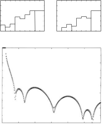
While it is straightforward to compute the reflectivity for a given model SLD profile, the so-called “direct problem,” deducing ρ from reflectivity data, the “inverse problem,” is much more problematic and inherently ambiguous because of the “lost” phase angle φ. Indeed, we see from Eqs. 12.9 and 12.10 that full knowledge of r needs three combinations of A, B, C, and D, viz., A2 + C2, B2 + D2, and AB + CD (because AD − BC = 1,these are not completely independent); while knowledge of |r|2 implies only the sum of squares combination, A2 + B2 + C2 + D2. In practice, the determination of an SLD profile from reflectivity data employs fitting schemes based on either model-dependent or model-independent methods (see [17, 18], for example). Figure 12.2 shows SLD profiles for a pair of model thin film structures, having thicknesses and SLD values typical of those of interest to us here (Fig. 12.2a), and the corresponding specular neutron reflectivities (Fig. 12.2b), which are nearly identical and thus demonstrate the importance of phase information
– or its absence. Even though it might not be possible to deduce from the reflectivity alone which of two or more SLD profiles is the veridical one, i.e., the one that actually produced the data, it can be concluded whether or not a given model SLD profile is at least consistent with the measured reflectivity. Furthermore, a priori knowledge of the SLD in part of the film or the adjacent substrate can be used to recover, in e ect, some of the phase information: this can also be accomplished by controlled manipulation of the SLD in certain sections of the film, i.e., by exchanging hydrogen for deuterium [19]. Such partial phase information can significantly reduce the number of acceptable solutions.
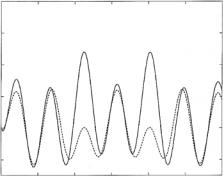
Methods have been developed to recover phase information through the use of various reference structures – either adjacent films or surrounding media [20–25]. For some of these, the reflection amplitude for the unknown part of the film can be obtained “locally” (i.e., independently at any k) and exactly [22, 24]. It has been shown, that the reflection amplitude and the SLD profile are in one-to-one correspondence for a large class of film potentials. This means that the given profile produces a unique spectrum of r and that a given r, if known for all Q, produces a unique SLD profile, when using the appropriate mathematical tools to retrieve it [26]. Figure 12.3 shows the real part
12 Membranes in Biology by Neutron Reflectometry |
231 |
(a)
) −2 Å
−6 ρ(10
3 |
|
|
|
|
|
|
|
|
|
3 |
|
|
|
|
|
|
|
|
|
2.5 |
|
|
|
|
|
|
|
|
|
2.5 |
|
|
|
|
|
|
|
|
|
2 |
|
|
|
|
|
|
|
|
|
2 |
|
|
|
|
|
|
|
|
|
1.5 |
|
|
|
|
|
|
|
|
|
1.5 |
|
|
|
|
|
|
|
|
|
1 |
|
|
|
|
|
|
|
|
|
1 |
|
|
|
|
|
|
|
|
|
0.5 |
|
|
|
|
|
|
|
|
|
0.5 |
|
|
|
|
|
|
|
|
|
0 |
Reference |
|
|
|
Backing |
0 |
Reference |
|
|
|
Backing |
||||||||
20 |
40 |
60 |
80 |
100 |
120 |
140 |
160 |
180 |
|
|
|
|
|
|
|
|
|
||
0 |
0 |
20 |
40 |
60 |
80 |
100 |
120 |
140 |
160 |
180 |
|||||||||
z (Å) |
z (Å) |
(b)1
0.01
Reflectivity
0.0001
1e-06
1e-08
1e-10
0 |
0.05 |
0.1 |
0.15 |
0.2 |
0.25 |
0.3 |
|
|
|
Q (Å−1) |
|
|
|
Fig. 12.2. Top: (a) Model SLD (neutron) profiles similar to two of the profiles considered for X-ray reflection (Fig. 12.3 of [44]). Both profiles share a common “reference” or known segment between z = 20 ˚A and z = 60 ˚A. Bottom: (b) Corresponding neutron reflectivity curves calculated for the two composite SLD profiles. The two curves are practically indistinguishable from one another (after Fig. 12.10 of [16])
of r (multiplied by Q2) for each of the two model SLD profiles of Fig. 12.2a. In stark contrast to the two corresponding reflectivity curves of Fig. 12.2b, there is a marked, clearly distinguishable di erence. An actual example which demonstrates the phase inversion technique is given in Sect. 12.5. In practice, the solution of the inverse problem is limited by the finite range of Q over which it is possible to measure the reflectivity, but ambiguities introduced by data truncation are systematic and to a limited extent, treatable [12, 27].
The reflection amplitude has a number of useful theoretical representations. If we know the solution ψ of Eq. 12.1 in region II, then an alternative, and quite general, expression for the free film r can also be derived [28] using the wave equation in Eq. 12.1,
232 C.F. Majkrzak et al.
2 xQ
Re r(Q)
8e-05
6e-05
4e-05
2e-05
0
−2e-05
0 |
0.05 |
0.1 |
0.15 |
0.2 |
0.25 |
0.3 |
Q (Å−1)
Fig. 12.3. Q2Re r(Q) for the (reversed) film structures of Fig. 12.2a (not including the backing but incorporating the known or reference sections of the films). These Re r(Q) correspond to what would be retrieved, for example, by phase-sensitive reflectivity experiments (for each of the two SLD profiles) in which the backing SLD was varied according to the methods discussed in the text. In contrast to the situation illustrated in Fig. 12.2b, these curves are markedly di erent over a wide range of Q. (after Fig. 12.9 of [16])
|
4π |
∞ |
|
r = |
|
−∞ ψ(z)ρII(z)eik0z z dz . |
(12.11) |
2ik0z |
Because ψ depends on r, Eq. 12.11 actually represents an implicit equation for r, but it does provide a useful starting point for formal analysis and for some practical approximation schemes.
12.2.2 The Born Approximation
In general, as seen from Eq. 12.11, the weaker the potential and the higher the wavevector transfer, the smaller the reflectivity becomes. For reflectivities of the order of a few percent or less, the neutron wave function within the scattering medium is not significantly distorted from its free space, plane wave form. In this case, ψ(z) in Eq. 12.11 can be approximated by the incident wave function, leading to the Born approximation (BA) or so-called “kinematic”
result, |
4π |
∞ |
|
|
|
||
rBA(Q) = |
|
−∞ ρII(z)eiQz dz . |
(12.12) |
iQ |
Thus, QrBA(Q) and ρII(z) are related by Fourier transformation. The factor of Q−1 multiplying the integral in Eq. 12.12 does not result from the BA; it is the same factor appearing in Eq. 12.11, the general expression, and is inherent in the e ective one-dimensionality of the specular reflection problem (i.e., the infinite-slab geometry of the 3D problem). The essential di erence is that the exact ψ(z, Q) approaches zero as Q goes to zero, unlike its plane wave
12 Membranes in Biology by Neutron Reflectometry |
233 |
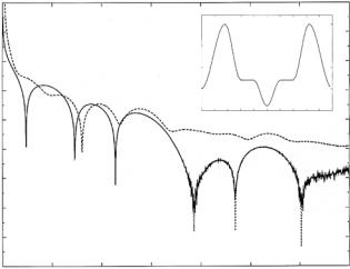
approximation, thus keeping r(Q) finite at Q = 0 in Eq. 12.11. Of course, it is to be expected that the BA will fail as Q → 0, since, as |r(Q)| → 1 at the origin, ψ(z, Q) becomes poorly approximated in region II by the “undistorted” incident wave. Figure 12.4 shows a model SLD profile for a lipid bilayer similar to that deduced in a neutron reflectivity study of DOPC multilayers by Wiener and White [29]. In Fig. 12.4 the specular neutron reflectivity |r|2 for the SLD profile is plotted as a function of Q, calculated using the exact theory and in the Born approximation for a freely standing single bilayer surrounded by vacuum. Also shown is the reflectivity for the same bilayer on a substrate (thick enough that it is e ectively semi-infinite) as predicted by the exact theory. In the latter case the Born approximation would fail not only at the origin, but also in the neighborhood of the critical angle for total external or mirror reflection (below which the reflectivity is unity).
12.2.3 Multilayers
In certain cases it is advantageous to reflect from a repeating or multilayered assembly of membrane films instead of a single membrane unit. Since the
Reflectivity
1
0.01
0.0001
1e-06
1e-08
1e-10
1e-12
1e-14
1e-16
1e-18 0
1.5e-06 |
|
|
|
|
|
|
|
|
|
|
|
|
|
|
|
|
|
|
|
|
|
|
|
|
|
|
1e-06 |
|
|
|
|
|
|
|
|
|
|
|
) |
|
|
|
|
|
|
|
|
|
|
|
|
2− |
5e-07 |
|
|
|
|
|
|
|
|
|
|
|
ρ(Å |
|
|
|
|
|
|
|
|
|
|
||
|
|
|
|
|
|
|
|
|
|
|
|
|
|
0 |
|
|
|
|
|
|
|
|
|
|
|
|
−5e-07 0 |
5 |
10 |
15 |
20 |
25 |
30 |
35 |
40 |
45 |
50 |
|
z (Å)
0.2 |
0.4 |
0.6 |
0.8 |
1 |
1.2 |
1.4 |
Q (Å−1)
Fig. 12.4. Model SLD profile for a lipid bilayer as discussed in the text (inset). Specular reflectivity for the SLD profile calculated according to the exact theory as well as in the Born approximation, assuming the bilayer to be free standing. Also plotted is the reflectivity calculated according to the exact theory for the same bilayer film but on a semi-infinite substrate of Si. The reflectivities according to the exact theory and the BA are virtually indistinguishable on a logarithmic scale for the free standing films, except in the neighborhood of the origin. Only the reflectivity for the film on the substrate has a region of total external reflection (long-dashed curve)