

Kluwer - Handbook of Biomedical Image Analysis Vol
.3.pdfInverse Consistent Image Registration |
249 |
information. IEEE Transactions on Medical Imaging, Vol. 16, No. 2, pp. 187–198, April 1997.
[28] Wells III, W. M., Viola, P., Atsumi, H., Nakajima, S., and Kikinis,
R., Multi-modal volume registration by maximization of mutual information. Medical Image Analysis, Vol. 1, No. 1, pp. 35–51, 1996.
[29]Christensen, G. E., Rabbitt, R. D., and Miller, M. I., 3D brain mapping using a deformable neuroanatomy. Physics in Medicine and Biology, Vol. 39, pp. 609–618, 1994.
[30]Miller, M. I., Banerjee, A., Christensen, G. E., Joshi, S. C., Khaneja, N., Grenander, U., and Matejic, L., Statistical methods in computational anatomy. Statistical Methods in Medical Research, Vol. 6, pp. 267–299, 1997.
[31]Christensen, G. E., Rabbitt, R. D., Miller, M. I., Joshi, S. C., Grenander, U., Coogan, T. A., and Essen, D. C. Van., Topological properties of smooth anatomic maps. In: Information Processing in Medical Imaging, Bizais, Y., Braillot, C., and Di Paola, R., eds, Vol. 3, pp. 101–112. Kluwer Academic Publishers, Boston, June 1995.
[32]Rueckert, D., Sonoda, L. I., Hayes, C., Hill, D. L. G., Leach, M. O., and Hawkes, D. J., Nonrigid registration using free-form deformations: application to breast MR images. IEEE Transactions on Medical Imaging, Vol. 18, No. 8, pp. 712–721, 1999.
[33]Christensen, G. E., Consistent linear-elastic transformations for image matching. In: Information Processing in Medical Imaging, Kuba, A. and Samal, M., eds, LCNS 1613, Springer-Verlag, Berlin, pp. 224–237, 1999.
[34]Johnson, H. J. and Christensen, G. E., Consistent landmark and intensity-based image registration. IEEE Transactions on Medical Imaging, Vol. 21, No. 5, pp. 450–461, 2002.
[35]Magnotta, V. A., Bockholt, H. J., Johnson, H. J., Christensen, G. E., and Andreasen, N. C., Subcortical, cerebellar and MR based consistent brain image registration. NeuroImage, Vol.19, No. 2, pp. 233–245, 2003.
250 |
Christensen |
[36]Baojun, Li, Christensen, Gary E., Dill, John, Hoffman, Eric A., and Reinhardt, Joseph M., 3D inter-subject warping and registration of pulmonary CT images for a human lung model. In: Proceedings of Medical Imaging 2002: Physiology and Function from Multidimensional Images, Clough, A. V. and Chen, C. T., eds, SPIE San Diego, CA, Vol. 4683, pp. 324– 335, 2002.
[37]Li, Baojun, Christensen, Gary E., McLennan, Geoffrey, Hoffman, Eric A., and Reinhardt, Joseph M., Establishing a normative atlas of the human lung: Inter-subject warping and registration of volumetric CT. Academic Radiology, Vol. 10, No. 3, pp. 255–265, March 2003.
[38]Christensen, G. E., He, J., Dill, J. A., Rubinstein, J. T., Vannier, M. W., and Wang, G., Automatic measurement of the labyrinth using image registration and a deformable inner ear atlas. Academic Radiology, Vol. 10, No. 9, 2003.
[39]Bookstein, F. L., Linear methods for nonlinear maps: Procrustes fits, thin-plate splines, and the biometric analysis of shape variability. In Toga [42], pp. 157–181, 1999.
[40]Joshi, S. C., Miller, M. I., Christensen, G. E., Banerjee, A., Coogan, T. A., and Grenander, U., Hierarchical brain mapping via a generalized Dirichlet solution for mapping brain manifolds. In: Proceedings of SPIE Vol. 2573, Melter, R. A., Wu, A. Y., Bookstein, F. L., and Green, W. D., eds, Vision Geometry IV, pp. 278–289, 1995.
[41]Grenander, U. and Miller, M. I., Computational anatomy: An emerging discipline. Quarterly of Applied Mathematics, Vol. 56, pp. 617–694, 1998.
[42]Brain, Warping., A., Toga, ed. Academic Press, San Diego, 1999.

Chapter 7
A Computer-Aided Design System
for Segmentation of Volumetric Images
Marcel Jackowski1 and Ardeshir Goshtasby2
7.1 Introduction
Image segmentation is the process of partitioning an image into meaningful regions. For the regions to be meaningful, they should represent objects or their parts. Difficulties arise when properties within objects vary or boundaries of objects become blurred. The problem is worsened when sensor inaccuracies exist and noise is present in the image. These variations, which are often unpredictable, make it impossible to develop an automatic method that can segment all images correctly. Because a high accuracy is demanded in the segmentation of medical images, the user has a critical role in examining the results and correcting the possible errors.
Image segmentation is perhaps the most studied area in image analysis. A large number of papers on this topic is published annually in image analysis journals and conference proceedings. The developed methods often take into consideration various properties of images or objects, and when such properties deviate from the anticipated ones, errors occur. Even for a limited class of images, for instance MR brain images, various methods have been developed, none of which is guaranteed to work correctly on a new image. This may be because there are sensor variations; variations in the brain’s shape, size, and
1 Department of Computer Science and Engineering, Wright State University, Dayton, OH
45435, USA
2 PET Section, Kettering Medical Center, Kettering, OH45429, USA
251

252 |
Jackowski and Goshtasby |
intensity distribution; and variations in intensities of tissues surrounding the brain. Since an error-proof image segmentation method cannot be developed, user assistance is needed to correct the obtained errors. At present, the best one can hope for is to have a segmentation method that can correctly find most areas of an object of interest, and in areas where it makes a mistake, allow the user to correct them.
We have developed a computer-aided design system that allows a user to revise the result of an automatically determined segmentation. We assume the region obtained by an automatic method has a spherical topology. We also assume the region represents voxels forming the bounding surface of an object of interest in a volumetric image. The developed system fits a parametric surface to the voxels and overlays the surface with the volumetric image. By viewing both the image and the surface, the surface is edited until the desired shape is obtained. The idea behind the proposed method is depicted in Fig. 7.1.
Various user-guided and interactive segmentation methods have been developed. Barrett, Falcao,˜ Udupa, Mortensen, and others [1, 8, 21, 22, 26] describe
|
|
|
|
|
|
|
|
|
|
|
|
|
|
revisions |
|
|
|
|
|
|
|
|
|
|
|
|
|
|
|
|
|
|
|
|
|
|
|
|
|
|
|
|
|
|
|
|
|
|
|
|
|
|
digital shape |
|
|
|
surface model |
|
|
|
|
|
|
|
|
|
|
|
|
ROI |
|
|
3-D interactive |
|
|||||
|
Automatic |
||||||||||||||
|
|
|
|
|
|
|
|||||||||
|
Segmentation |
|
|
|
|
Modeling |
|
|
|
|
Editing |
|
|||
|
|
|
|
|
|
|
|
||||||||
|
|
|
|
|
|
|
|
|
|
|
|||||
|
|
|
|
|
|
|
|
|
segmentation |
|
|
||||
|
|
volumetric |
|
|
|
|
|
|
|
|
|
||||
|
|
image |
|
|
|
|
|
|
|
result |
|
|
|||
Figure 7.1: The computer-aided design system used in region editing. The system starts with a region obtained from an automatic segmentation method. It then represents the region by a free-form parametric surface and overlays the surface with the volumetric image. The user then revises the surface while viewing both the volumetric image and the surface. The final result is generated parametrically or in digital form.
Image Segmentation |
253 |
a method known as “live-wire” with which a user roughly draws the boundary of a region of interest. An automatic process then takes over and revises the boundary by optimizing a cost function. An alternative method is introduced that allows the user to select a number of points on the region boundary, and the program then automatically finds boundary segments between consecutive points, again by minimizing the related cost functions. These methods have been optimized for speed [9]. They have also been extended to 3D [7]. In 3D, the program receives boundary contours in a few strategically placed slices and produces contours in other slices.
Cabral et al. [4] describe editing tools that are associated with a regiongrowing method, enabling a user to add or remove image voxels in a region to revise the region. Hinshaw and Brinkley [14] developed a 3D shape model that uses prior knowledge of an object’s structure to guide the search for the object. Object structure is interactively specified with a graphical user interface.
Hohne¨ and Hanson [15] developed low-level segmentation functions based on morphological operators that interactively delineate regions of interest. Pizer et al. [24] describe a method that segments a volumetric image into regions at a hierarchy of resolutions. Then, the user, by pointing to an object in a crosssectional image at a certain resolution, selects and revises a region. Welte et al. [27] describe an interactive method for separating vessels from each other and from the background in MR angiographic images. To reduce the complexity of the displayed structures during the interactive segmentation, a capability to select substructures of interest is provided.
Energy-minimizing models or “snakes” are another set of tools that can be used to guide a segmentation and revise the obtained results [18, 20]. With an energy-minimizing model, a contour or a wireframe is initiated approximately where an object of interest is believed to exist. An optimization process is then activated to iteratively revise the contour or the wireframe to minimize a local cost function that defines the energy of the snake. Since some points in a snake may trap in local minima, the globally optimal solution may be missed. To avoid this, often the user is allowed to intervene and either move some of the snake’s points that are thought to have converged to local minima, or guide the snake to the optimal position by interactively controlling the external forces.
An interactive segmentation method based on a genetic algorithm is described by Cagnoni et al. [5]. In this method, the boundary contour of a region of interest is manually drawn in one of the slices. The boundary contour is then
254 |
Jackowski and Goshtasby |
considered an initial contour in the subsequent slice and the contour is refined by a genetic algorithm using image information. The refined boundary is then considered an initial contour in the next slice and the process is repeated until all slices in a volumetric image are segmented. Interactive segmentation methods provide varying levels of user control. The control can be as little as selecting a contour among many [19] or as much as manually drawing a complete region boundary. Methods that require a lot of user interaction are highly reliable, but they also have a high interuser variability. On the other hand, methods that require very little user interaction are not as reliable, but they have a low interuser variability. A survey of interactive segmentation methods providing different levels of user control is given by Olabarriaga and Smeulders [23].
The new idea introduced in this paper is to use the capabilities of a computeraided design system to quickly and effectively refine the result of a 3D segmentation, just like editing a 3D geometric model. By having a mental picture of an object of interest and viewing the information present in a volumetric image, the user interactively modifies the result of an automatically obtained segmentation until the desired shape is sculpted. This is achieved by representing the region by a parametric surface and overlaying the surface with the volumetric image. Then, the user views both the image and the surface together and modifies the surface until the satisfactory region is obtained.
We assume an automatic segmentation method that correctly finds most parts of a region of interest is available. The capability introduced in this paper enables the user to revise parts of the region that are believed to be inaccurate. This revision is achieved through a mechanism that sculpts a desired shape from a rough initial one. The proposed method is not the same as a dynamic snake model that creates a desired shape by interactively changing the external forces that guide the snake [20]. Rather, it is based on a parametric surface fitting and editing model.
7.2 The Computer-Aided Design System
We assume a volumetric image has been segmented and a region of interest has been extracted. We also assume the given region is composed of connected voxels that represent the bounding surface of an object of interest. We will call such a region a digital volumetric shape, or a digital shape. In the following, a
Image Segmentation |
255 |
method that approximates a digital shape by a parametric surface is described. Since voxels belonging to a digital shape do not usually form a regular grid, we choose the rational Gaussian (RaG) formulation [11, 12], which does not require a regular grid of control points to represent a free-form shape. We will show how to parametrize voxels in a digital shape and how to determine the control points of a RaG surface that approximate the digital shape by the least-squares method. The obtained RaG surface is then overlaid with the volumetric image and the user is allowed to revise the surface by moving its control points.
7.2.1 Surface Approximation
Given a set of (control) points {Vi : i = 1, . . . , n}, the RaG surface that approximates the points is given by [11, 12]
n
P(u, v) = |
Vigi(u, v), |
u, v [0, 1], |
(7.1) |
|||
|
i=1 |
|
|
|
|
|
where gi(u, v) is the ith blending function of the surface defined by |
|
|||||
gi(u, v) |
|
Gi(u, v) |
(7.2) |
|||
|
|
|
, |
|||
|
n |
|
||||
|
|
= j=1 |
G j (u, v) |
|
||
and Gi(u, v) is a 2D Gaussian of height 1 centered at (ui, vi): |
|
|||||
Gi(u, v) = exp{−[(u − ui)2 + (v − vi)2]/2σ 2}. |
(7.3) |
|||||
{(ui, vi) : i = 1, . . . , n} are the parameter coordinates associated with the points. The parameter coordinates determine the adjacency relation between the points. In the subsequent section, we will see how to estimate them. Formulas (7.1)– (7.3) are for an open surface. If a surface is required to close from one side, like a generalized cylinder, formula (7.3) should be replaced with
∞
Gi(u, v) = |
exp{−[(u − ui)2 + (v − vi + k)2]/2σ 2}. |
(7.4) |
|
k=−∞ |
|
If the opening at each end of a generalized cylinder converges to a point, a closed surface will be obtained. In a cylindrical surface, a 2D Gaussian wraps around the closed side of the surface infinitely. However, since a Gaussian approaches zero exponentially, its effect vanishes after a few cycles. Therefore, in practice, the ∞ in formula (7.4) is replaced with a small number such as 1 or 2 [11]. An alternative method for obtaining a closed surface is to use the
256 |
Jackowski and Goshtasby |
formulation of a torus, which is closed along both u and v. Staib and Duncan [25] make a torus that closes at two points and separate the segment between the points by selecting proper weights in the formulation of the torus. An alternative method [13] is to transform a torus to a sphere by giving the exterior and interior circles that define the torus the same center and the same radius, allowing parametrization of an object with spherical topology using parameter coordinates of the torus.
The standard deviation of Gaussians in formulas (7.3) and (7.4) determines the smoothness of a generated surface. A surface with a smaller standard deviation represents local details better than a surface with a larger standard deviation. The larger the standard deviation, the smoother the obtained surface.
When the control points are the voxels representing a closed 3D region, the region can be represented by a parametric surface by mapping the voxels to a sphere. RaG surfaces described by Eqs. (7.1), (7.2) and (7.4) represent surfaces with a spherical topology. Assuming parameters φ [−π/2, π/2] and θ [0, 2π ] represent spherical coordinates of voxels defining an object, we will need to set u = (φ + π2 )/π and v = θ /2π in the equations of a half-closed RaG surface. In the following section, we will show how to spherically parametrize voxels in a closed digital shape, and in the subsequent section, we will show how to find the control points of a RaG surface in order to approximate a digital shape while minimizing the sum of squared errors.
7.2.2 Parametrizing the Shape Voxels
Brechbuhler¨ et al. [2, 3] describe a method for mapping simply connected shapes to a sphere through an optimization process. Although this method can find parameters of voxels in various shapes, the process is very time consuming. We use the coarse-to-fine method described in [17] to parametrize a digital shape. In this method, first, a digital shape is approximated by an octahedron and at the same time a sphere is approximated by an octahedron. Then, correspondence is establishes between triangles in the shape approximation and triangles in the sphere approximation. By knowing parameters of octahedral vertices in the sphere approximation, parameters of octahedral vertices in the shape approximation are determined. This coarse approximation step is depicted in Fig. 7.2. The process involves placing a regular octahedron inside the shape and extending its axes until they intersect the shape and replacing the octahedral vertices
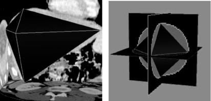
Image Segmentation |
257 |
(a) |
(b) |
Figure 7.2: (a) Approximation of a digital shape by an octahedron. (b) Approximation of a sphere by an octahedron. Parameter coordinates of octahedral vertices in the sphere are assigned to the octahedral vertices in the shape.
with the obtained intersection points. The center of the octahedron is placed at the center of gravity of the shape and its axes are aligned with the axes of the shape [10]. If the shape is very irregular so that the center of gravity of the shape falls outside the shape, the intersection of the major axis of the shape with the shape is found and the midpoint of the longest segment of the axis falling inside the shape is taken as the center of the octahedron.
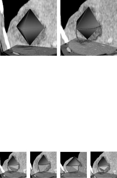
Next, the voxels associated with each triangle in the octahedral approximation are determined. This is achieved by finding the bisecting plane of each octahedral edge and determining the shape voxels that lie in that plane. In Fig. 7.3b, the bisecting planes passing through the edges of a triangle and intersecting the shape are shown. The bisecting plane passing through each octahedral edge and intersecting the shape will be an edge contour. A triangle, therefore, produces three edge contours that start and end at the vertices of the triangle and enclose the shape voxels that belong to that triangular face in the octahedral approximation. The triangles obtained in the octahedral subdivision are entered into a list. After this initial step, a triangle is removed from the list and is subdivided into smaller triangles and the triangles whose distances to the associating triangular patches are larger than a given tolerance are again entered into the list. In this manner, the triangles are removed from the list, one at a time, and processed until the list becomes empty.
258 |
Jackowski and Goshtasby |
(a) |
(b) |
Figure 7.3: (a) Octahedral approximation of a shape. (b) Edge contours delimiting a triangular patch.
Subdivision of a triangle is achieved as follows. If distances of voxels in an edge contour to the associating edge are all within the required tolerance, that edge is not subdivided. Otherwise, the farthest voxel in the contour to the edge is used to segment the contour, producing two smaller contours. The farthest contour point is then connected to the end points of the contour to produce two new edges. In this manner, a triangular face is subdivided into 2, 3, or 4 smaller triangles depending on whether 1, 2, or 3 edges of the triangle are replaced with smaller edges. This is depicted in Figs. 7.4a–7.4c. If distances of voxels in all edge contours to corresponding edges in a triangle are below the required tolerance, a test is performed to determine whether or not distances of voxels associated with the triangle are within a required tolerance to that triangle. If all distances
(a) |
(b) |
(c) |
(d) |
Figure 7.4: (a)–(c) Subdividing one, two, or three of the triangular edges, respectively. (d) When no more triangular edges can be subdivided, error between the triangular patch and the associating triangle is determined and, if that error is above the given tolerance, the farthest voxel in the patch to the triangle is determined and used to subdivide the triangle.