

A.3 Indexing of crystal faces and zones 283
A.3 Indexing of crystal faces and zones
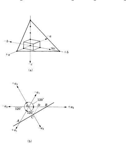
The indices of crystal faces are traditionally expressed by the points at which the lattice plane parallel to the face cuts the a-, b-, and c-axes, respectively. Indices are always expressed as integers. A particular face is expressed by parentheses ( ), and crystallographically equivalent faces are denoted by curly brackets { }. Miller indices use the reciprocal number of the unit length at which the respective axes are cut, and are widely adopted.
For example, a crystal face that is parallel to the a- and b-axes but intersects the c- axis may be expressed in the form ( 1) (this is called the Weiss index), but this can be expressed in Miller index form as (1/ , 1/ , 1/1) (001), and the positive and negative orientation of each respective axis is distinguished by adding a bar above the index: (001) and (001). In the cubic system, (100), (100), (010), (010), (001), and (001) are all crystallographically equivalent faces, and so they can be denoted by {100}.
(643) |
Figure A.3.1.

284Appendixes
In the tetragonal system, (100), (100), (010), and (010) are crystallographically equivalent and can be expressed by {100}, but (001) and (001) are not included in this
system. A crystal face cutting the a-, b- and c-axes by 2, 3, and 4 units is indexed as (1/2, 1/3, 1/4) (6/12, 4/12, 3/12) (643). See Fig. A.3.1(a).
Since a subsidiary axis a3 is assumed in addition to the a1 and a2 axes in the hexagonal system (and in the hexagonal expression of the trigonal system), the
index is expressed by four indices for a general face (hkıl). This is called the
Miller–Bravais index. For example, in Fig. A.3.1(b) a face ACB cuts the a1 and a2 axes at 1 ( OA, OB), and the a3 axis at OC OD OB/2. Therefore this face is indexed as (1120). From geometry, h(1) k(1) i(2).
Crystal zones are crystallographic directions, which express the direction of an edge formed by two crystallographic faces, or the direction perpendicular to a crystal face, or the direction of a crystallographic axis. This corresponds to a point row in a crystal lattice. Their indices are expressed by integer numbers arranged in the order of the a-, b-, and c-axes [uvw] (a specific zone), uvw (general zone), similar to the case of the face index. The zone perpendicular to the (001) face (c-axis) is expressed as 001 . The index of an edge formed by two crystal faces can be easily obtained by the crossing multiplication method, as follows.
When a face index has a minus sign, this should be taken into consideration in the multiplication. A crystal face (hkl) determined by two zones [u1v1w1] and [u2v2w2] can be similarly obtained by the crossing multiplication method.
The indexing of crystal faces and zones was achieved using morphologically determined axial ratios and angles before the commencement of X-ray structural analyses. In most cases, morphologically determined axial ratios and angles were in accordance with structurally determined unit cell parameters, but in some cases the two were not the same. In such cases, structurally deduced indexes have become more commonly used. For example, the cleavage face of CaCO3 is [1011] in
morphological indexing, but the structurally determined index [1014] has become more generally used. However, since morphological indexes are more straightforward in dealing with morphological problems, morphological indexing is adopted in this book.
A.5 Stereographic projections 285
A.4 Symmetry elements and their symbols
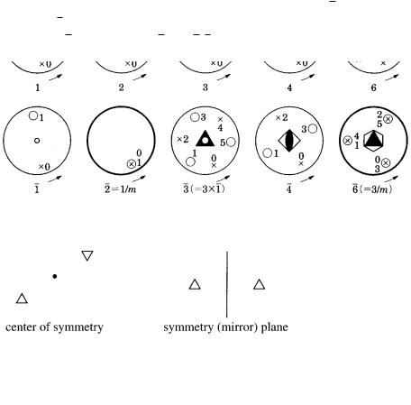
In the upper row of Fig. A.4.1, rotation axes 1, 2, 3, 4, and 6, and in the lower row,
rotation-inversion axes 1, 2, 3, 4, and 6 are illustrated by stereographic projections. Symbols and denote the positions of a general face projected onto the northern and southern hemispheres, respectively. Numbers 0, 1, 2, 3, 4, and 5 are orders appearing by rotation or rotation inversion. A center of symmetry is expressed by ●, and a symmetry plane is expressed by thick lines; 1 has a center of symmetry, 2 corresponds to the symmetry plane perpendicular to 1, and so can be expressed as 2 1/m. Similarly, 3 3 1, 6 3/m.
Figure A.4.1.
A.5 Stereographic projections of the symmetry involved in the thirty-two
crystal classes (point groups)
Please refer to Table A.5.1. In each row a general face is shown on the left, and the symmetry elements appear on the right; Hermann–Mauguin symbols are shown beneath. Points on the general face are distinguished by ● for the northern hemisphere and ● for the southern hemisphere. For symmetry element symbols, refer to Appendix A.4.

286 Appendixes
Table A.5.1
|
|
|
Triclinic |
|
Monoclinic/ |
Tetragonal |
||||||||||||
|
|
|
|
|
|
|
|
|
orthorhombic |
|
|
|
|
|
||||
|
|
|
|
|
|
|
|
|
|
|
|
|
|
|
|
|
|
|
X |
|
|
|
|
|
|
|
|
|
|
|
|
|
|
|
|
|
|
|
|
1 |
|
|
2 |
|
|
4 |
|
|||||||||
|
|
|
|
|
|
|
|
|
|
|
|
|
|
|
|
|
|
|
X |
|
|
|
|
|
|
|
|
|
|
|
|
|
|
|
|
|
|
|
|
|
|
|
|
|
|
|
|
|
|
|
|
|
||||
|
|
1 |
|
|
|
|
|
m ( 2) |
4 |
|
||||||||
X/m |
|
|
|
|
|
|
|
|
|
|
|
|
|
|
|
|
||
|
1/m 2 |
|
|
|
|
|
|
|
|
|
|
|||||||
|
|
|
|
|
|
|
|
|
|
|
2/m |
|
4/m |
|||||
Xm |
|
|
|
|
|
|
|
|
|
|
|
|
|
|
|
|
||
|
1/m 2 |
|
|
|
|
|
|
|
|
|
|
|||||||
|
|
|
|
|
|
|
|
|
|
|
mm2 |
4mm |
||||||
|
|
|
|
|
|
|
|
|
|
|
|
|
|
|
|
|
|
|
Xm |
1m 2/m |
2m mm2 |
|
|
|
|
|
|||||||||||
|
|
|
|
|
|
|
|
|
|
|
|
|
|
|
|
|
|
|
|
|
|
|
|
|
|
|
|
|
|
|
|
|
|
42m |
|||
X2 |
12 2 |
222 |
422 |
X/mm |
1/mm mm2 |
mmm |
4/mmm |
|
|
|
|
|
|
|
|
|
|
|
|
|
|
|
|
|
|
A.5 Stereographic projections 287 |
||||
|
|
|
|
|
|
|
|
|
|
|
|
|
|
|
|
|
|
|
|
|
|
|
|
|
|
|
|
|
|
|
|
|
|
|
|
|
|
Trigonal/ |
Hexagonal |
|
|
Cubic |
||||||||||||||
rhombohedral |
|
|
|
|
|
|
|
|
|
|
||||||||
|
|
|
|
|
|
|
|
|
|
|
|
|
|
|
|
|
|
|
3 |
|
|
|
|
6 |
23 |
|
|||||||||||
|
|
|
|
|
|
|
|
|
|
|
|
|
|
|
|
|
||
|
|
|
|
|
|
|
|
|
|
|
|
|
|
|
23 2/m3 |
|||
|
|
|
|
|
|
|
|
|
|
|
|
|
|
|
||||
3 |
|
|
|
|
6 |
|
|
|
|
|
||||||||
|
|
|
|
|
|
|
|
|
|
|
|
|
|
|
||||
3/m 6 |
|
|
|
|
|
|
|
|
|
|
||||||||
|
|
|
|
|
|
|
|
|
|
6/m |
|
|
m3 |
|||||
|
|
|
|
|
|
|
|
|
|
|
|
|
|
2m3 2/m3 |
||||
3m |
6mm |
|
|
|
|
|
||||||||||||
|
|
|
|
|
|
|
|
|
|
|
|
|
|
|
|
|||
3m |
6m2 |
|
|
43m |
||||||||||||||
32 |
|
|
|
|
622 |
432 |
|
|||||||||||
|
|
|
|
|
|
|
|
|
|
|
|
|
|
|
|
|
|
|
3/mm 6m2 |
|
|
|
|
|
|
|
|
|
|
||||||||
6/mmm |
m3m |
|
|
|
|