

5.9 Bunching 107
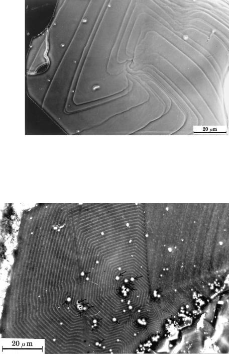
Figure 5.12. Phase contrast photomicrograph of a composite spiral in SiC, (0001). White patches indicate impurities selectively adhering at the outcrops of dislocations. Each white patch corresponds to one dislocation. Arrows indicate an elemental spiral.
same Burgers vector, but opposite signs, occur close together, spiral steps from the two dislocations will coalesce to form a common terrace surface and will advance as a closed loop. If the separation between the two dislocations is wider than 19rc, each forms a spiral pattern with a few turns, after which the steps will advance as a closed loop. From screw dislocations situated closer together than 19rc, a closed loop appears from the beginning. Therefore, it is not advisable to come to the rash conclusion, based simply on the observation that no spiral pattern is observable at the center of step pattern, that the growth is not by the spiral growth mechanism.
If a new dislocation is introduced while a spiral step is advancing, the new step from the new dislocation will be affected by the advancement of the earlier spiral step, and can have only one-half or a couple of turns. This results in the coexistence of spirals with a small number of turns with those covering a wide area; Fig. 5.14 is such an example.
5.9Bunching
When we observe the process of advancement of elemental spiral steps in situ, it is often noticed that two steps bunch together to form a step with the height of two layers as they advance. The advancing rate of the bunched layer is retarded
108 Surface microtopography of crystal faces
Figure 5.13. Positive phase contrast photomicrograph of composite spiral in hematite, (0001). A bright contrast appears on the higher side of a step. By tracing the route from the lowest step to higher steps, the lowest step becomes the highest step after one turn, corresponding to Escher’s staircase. Since the curvatures of the steps are reversed at the center of a group of dislocations, a depression appears due to the associated strain field (refer to Section 5.7). See also Fig. 5.11.
Figure 5.14. Phase contrast photomicrograph of dominant and dominated spirals (arrows) in SiC, (0001).

5.9 Bunching 109
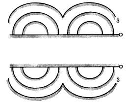
Figure 5.15. The profile of a kinematic shock wave [17]: (a) growth; (b), (c) dissolution. In (b) and (c), dissolution steps advance from left to right, and shock waves appear at P and Q.
compared with that of a single step, and the form is perturbed. As the bunching progresses and the height increases, the forms become more perturbed. Step bunching may be regarded as a similar phenomenon to a traffic jam in which vehicles initially advance at a constant rate, then bunch. The wave profile of the macrosteps appearing due to a traffic-jam-like effect was solved by Frank [17]. Such a wave is called a kinematic shock wave, and the profile is as shown in Fig. 5.15.
There can be many reasons why step bunching occurs: fluctuation of the supersaturation on the surface; asymmetry in the surface diffusion between the upper and lower terraces of a step; impurity adsorption; or the presence of foreign or differently oriented particles may affect the rate of advancement of a step, and act as reasons for step bunching to occur. Supersaturation affects directly the rate of step advance. Asymmetry in surface diffusion is called the Schwoebel effect [18], which results in fluctuations in the step advance rate due to the asymmetry between the incorporation of the adsorbed molecules into steps coming from the upper terrace and those on the lower terrace. The effect of impurity adsorption at a step upon the step advancement rate was analyzed theoretically by Cabrera and Vermilyea [14], [15] in terms of the pinning effect. Impurity components that are difficult to incorporate into the crystal cause drastic effects upon the advancing rate of a step at parts per million order. Similar effects may be seen in the cases of foreign particles and differently oriented particles precipitated on a growing surface, around which the advancing rate of a step is retarded and the step takes on a curved form,
110 Surface microtopography of crystal faces
(a) |
(b) |
|
|
(c)
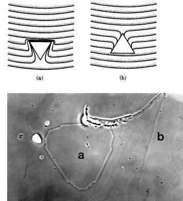
Figure 5.16. Difference in step patterns for the case in which (a) foreign particles or the same crystal particles with different orientation precipitate on a growing surface, and
(b) in which the same crystal particles precipitate in the same orientation. The shaded side indicates the higher side of the steps. (c) Actual example of cases shown in (a) and (b), observed on a (0001) face of hematite.
engulfing the particles. When a particle of the same crystal precipitates with the same orientation on the growing surface, the step advancement rate increases as it approaches the particle, and a step pattern appears as if the step is sucked in by the particle. Two cases are shown in Fig. 5.16.
In this way, elemental steps bunch together, forming irregular macro-steps in the process of advancement (Fig. 5.17). In real crystal growth processes, it is usual that growth centers are present on one crystal face, and so interference and cooperation occur among the steps, resulting in the formation of step patterns resembling the contour lines on a geographic map (see Fig. 5.10).
5.10Etching
We may assume that the surface microtopographs that appear due to growth are symmetrical to those that appear by dissolution, since the processes of
5.10 Etching 111
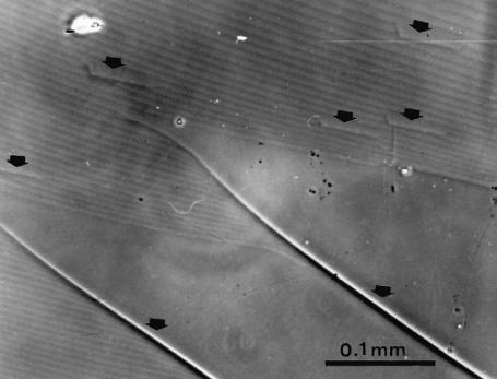
Figure 5.17. Phase contrast photomicrograph showing bunching of elemental spiral
steps (arrows) in hematite, (0001) face.
growth and etching are assumed to be symmetrical. However, the role played by dislocations, impurities, and point defects in the respective processes is not the same. This is because the role of the strain field is different in growth and dissolution. For example, point defects cannot be active growth centers, but they do act as active centers in etching. Screw and edge dislocations play the same role in etching, but not in growth.
With regard to the attachment and detachment energies, the corners of a crystal or a rough interface that is constructed by kinks alone are sites where the process proceeds most quickly, whereas the low-index crystal faces, corresponding to smooth interfaces, represent the direction with the minimum rate of normal growth and dissolution. As a result, if a single crystalline sphere is dissolved in an isotropic environmental phase, a dissolution form bounded by both flat and curved crystal faces appears. This is called the dissolution form, which is not the same as the growth form.
If a crystal face with step patterns appearing by spiral growth is etched in a weak dissolution process, after growth the steps resulting from the growth process will retard two-dimensionally, essentially forming a step pattern by etching. Irrespective of whether the crystal is of circular or polygonal form, the growth steps are smooth, whereas steps formed by two-dimensional etching usually show minute
112 Surface microtopography of crystal faces
(a)
growth
(b)
dissolution
Figure 5.18. Difference between (a) growth steps and (b) steps formed by two-
dimensional etching.
unevenness. This is because strain fields associated with impurities and point defects affect the advancement of etching steps. As illustrated in Fig. 5.18, steps due to etching show a chopping wave form, different from protruded growth steps [19]. Through cooperation with etching from point defects outcropped on the terrace surface, a surface with one level lower than the surface of the growth step will appear between the position of the original step and the etch step. It was confirmed on a {0001} face of a natural hematite crystal that the depth of the etched surface corresponds to a few unit cells. This was analyzed and was found to correspond to the outermost layer, which had the highest concentration of point defects [19].
Since the strain fields present on crystal surfaces are preferential sites for etching to proceed, strain fields are sites where etch pits are formed at the sites of strain fields. There are two types of etch pit: flat-bottomed (F-type) and pointbottomed (P-type). Their morphology varies from circular to polygonal. Etch pits associated with point defects are F-type, whereas those associated with linear defects are P-type; both can coexist on the same surface (see Fig. 5.2). When etch pits are polygonal, the symmetry follows that of the face. Polygonal etch pits, irrespective of whether they are of P- or F-type, formed on a face of a single crystal by etching under certain conditions, take the same orientation, but, if the crystal is twinned, the orientations of the etch pits are reversed on the common surface of the two individuals. On the other hand, if the etching conditions are changed, polygonal etch pits with opposite orientations may appear, and sometimes etch pits in intermediate form, circular, and reversed forms may appear. The morphology of etch pits varies, like that of growth forms, depending on the conditions.
Since there is a strain field associated with a dislocation, etching originating from the outcrop at first forms a P-type etch pit. As etching proceeds further, a
5.11 Surface microtopography: Tracht and Habitus 113
tunnel is formed along the dislocation, starting from the bottom of the P-type etch pit, with a reversed trumpet form. Depending on the type of dislocation and the etching conditions, an etch tunnel with a hollow core will be formed along a dislocation line.
By the utilization of etching that selectively proceeds at strain fields associated with dislocations, etch pits have been utilized as a good method of measuring dislocation density and of investigating the movement of dislocations [20]. Etching agents and conditions were developed to form P-type etch pits by selectively etching dislocations. Sirtle etchant, HF : H2O 1 : 1 CrO3 is an example of such an agent, and it is used to investigate Si crystals.
Since dislocations are linear strain fields, if a crystal is treated in an appropriate atmosphere, impurity ions selectively precipitate along the dislocation. These can be detected by infra-red microscopes, and so the method was used to prove the presence of dislocations during the early period of dislocation studies. If a dislocation is decorated by metallic elements, the dislocations act as a resistance against etching, and only the portion apart from dislocations is etched, and decorated dislocations remain as protrusions. The resulting protrusions are etch hillocks.
5.11Surface microtopography: Tracht and Habitus
The Tracht and Habitus of polyhedral crystals bounded by flat faces are determined by the relative ratio of normal growth rates of faces appearing, and these morphologies are expected to appear under a driving force condition below
/kT *, where the spiral growth mechanism principally operates. Therefore, factors which affect the Tracht and Habitus of polyhedral crystals will also affect the forms and advancement rates of spiral growth steps on smooth interfaces. As summarized in this chapter, these factors are determined by whether steps are rough or smooth, by the edge free energy of the steps, and the driving force. So, anything that has an impact on these factors will also affect the Tracht and Habitus of polyhedral crystals. These factors will be summarized in the following.
Since the edge free energies, , are different for the vapor and solution phases, and particularly for solute–solvent interaction energies, the same crystal species will exhibit different Tracht and Habitus in different ambient phases and different solvents. If impurities are present in the system, this affects and the advancing rates of steps. There are two opposite cases in impurity effects, and, depending on the interface state, some will promote growth, whereas others will suppress growth.
The driving force, /kT, affects the advancement rate of steps, as well as the state of the interface. Growth temperature (and pressure) may modify the morphology of growth spiral layers and may affect Tracht and Habitus through the modification of the interface state, but the effect will appear through /kT.