

102Surface microtopography of crystal faces
whereas it is typically 102 3 on crystals grown from the solution phase (because the step separation is narrower) [12]. When the ratios are compared among crystals
grown from the same ambient phase, it can be seen that 0 becomes narrower as supersaturation increases. It is often observed that SiC crystals grown from the
vapor phase show a much narrower 0 at the spiral center than anywhere else (see Fig. 5.7(b)). This can be understood as being due to a sharp increase in supersatura-
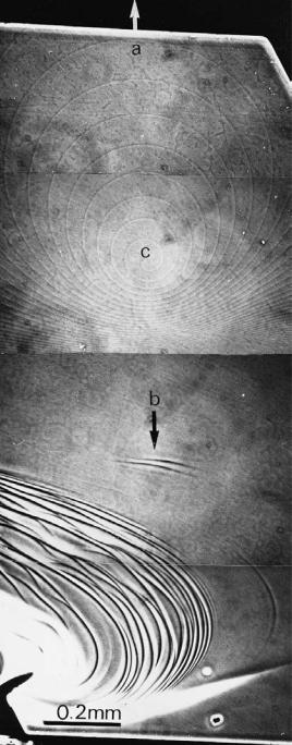
tion at the final stage of growth. There are cases of spirals originating from a screw dislocation that show extreme eccentricity. This is explained as being due to the supersaturation gradient over the surface owing to flow of vapor. Figure 5.9 shows an example of spiral patterns on a (0001) face of a SiC crystal synthesized by the
Rayleigh method [13]. The direction of narrowing of 0 is the direction towards the crucible wall. In the Rayleigh method, SiC platy crystals grow on and attach
obliquely to the wall of the crucible, which is made of sintered SiC powder. As a result, a supersaturation gradient is formed on the (0001) surface, forming eccentric spiral step patterns.
It is extremely unlikely that the whole surface of a crystal face is covered by step
patterns with constant 0. In general, 0 becomes narrower towards the edge. This is due to the fact that the driving force is higher at the edge than at the center, i.e.
the Berg effect.
It is often observed in tiny crystals of micrometer order, such as clay minerals, that the entire surface of a crystal face is covered by elementary spiral layers originating from one screw dislocation (Fig. 5.3). Figure 5.10(a) shows such an exceptional case observed on a (0001) face of a SiC crystal synthesized by the Acheson method. However, such a situation is almost exceptional on crystal faces larger than millimeter size, and is encountered only on crystals synthesized under very precisely controlled conditions. In general, there are many growth centers on one crystal face, and steps from these centers bunch together to form macro-steps, which constitute the step patterns of the face.
An example is shown in Fig. 5.10(b). However, step patterns observed on the same crystal face of the same crystal species collected from different locations usually exhibit characteristic patterns that are recognizable enough to indicate the locality of origin. This is because surface microtopographs reflect very sensitively the difference in growth conditions at respective sites.
5.7 Formation of hollow cores
Strain is concentrated along dislocation cores, and it increases as the Burgers vector of dislocations increases. It was Frank who predicted that above a critical value a dislocation is energetically more stable if a free surface is created along the dislocation core. This critical value is expressed by
b 8 2 / ,
5.7 Formation of hollow cores 103
Figure 5.9. Eccentric spiral pattern on a (0001) face of SiC, due to a supersaturation gradient over the surface [13]. The spiral center is indicated by c, and the arrows a, b show the directions of eccentricity (where the white arrow refers to the center of the crucible, and the black arrow refers to the wall).

104 Surface microtopography of crystal faces
(a)
(b)
Figure 5.10. (a) An exceptional case showing a wide (0001) surface of SiC with an area of 0.7 0.4 mm covered by spiral layers with a constant 0 originating from an isolated single screw dislocation. The step height is 1.5 nm. (b) Reflection photomicrograph at low magnification showing a commonly observed step pattern in hematite, (0001). The arrows indicate growth centers, where elemental spiral steps are observed. All observed macro-steps originate from these points, from where the elemental spiral steps advance.
5.8 Composite spirals 105
where b is the Burgers vector, is the rigidity, is the surface free energy, and is a factor close to unity. In the case of crystals with large , such as SiC, a hollow core is expected for a dislocation with b 2 nm, and a hollow core with a diameter of
100 nm is expected for b 10 nm. Indeed, hollow cores were observed at the centers of growth spirals [3].
That a hollow core is formed by the creation of a free surface along a dislocation core implies that the curvature of the spiral step is reversed due to the strain field along the dislocation core. The effect of a strain field upon the advancement of a step was theoretically treated by Cabrera and Levine [14], [15].
Only a few crystals exhibit hollow cores at the centers of growth spiral layers. However, on the (0001) faces of SiC, which has a large value, hollow cores due to growth have often been observed. According to the summary by Sunagawa and Bennema [16], various degrees of the effect of the strain associated with dislocation cores have been observed depending on the sizes of b and the concentration of dislocations.
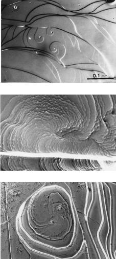
In the case of growth spirals originating from dislocations with large b, hollow cores with diameters of micrometer order are observed at the spiral center; however, when a number of dislocations with small b concentrate in a narrow area, a basin-like depression appears at the central area of the composite spirals, since the curvature of advancement of the spiral steps is reversed near the center. A straight step may appear near the spiral center as an intermediate state in the reversal of step curvature. Several examples are shown in Fig. 5.11.
Hollow cores associated with dislocations may be formed in both growth and etching processes.
5.8Composite spirals
Elemental spiral steps originating from dislocations form various composite step patterns through cooperation or repulsion depending on the sign of dislocations and the distance between neighboring dislocations.
When spiral growth layers advance from dislocations with the same sign (Burgers vector) and with distance smaller than one-half of the radius of the critical two-dimensional nuclei ( 0/2 19rc/2), a composite step pattern consisting of the same number of spiral steps as dislocations will be formed (Fig. 5.12). At the center, spiral steps will advance by mutually interchanging the centers. If the separation between a pair of dislocations among many neighboring dislocations is narrower than the others, the advancement of the spiral steps from other dislocations is influenced by these steps, and bunching of steps will occur rhythmically. Figure 5.13 is a positive phase contrast photomicrograph of composite spirals on a (0001) face of a hematite crystal. In positive phase contrast, the bright contrast appears exclusively on the higher side of a step, and so it is possible to determine
106 Surface microtopography of crystal faces
(a)
(b)
(c)
Figure 5.11. Various step patterns appear because the advancing rate and the curvature of the spiral layers are affected by the strain field at dislocation cores.
(a) Central hollow core (SiC). (b) Basin-like depression formed at the central area of composite spirals (hematite). (c) Straight step near the center (hematite).
unambiguously which side is higher. If we check the photograph from this viewpoint and start from a step and go successively to the higher side, we see that, as we rotate around the center, that the lowest step eventually corresponds to the highest step. This is comparable to Escher’s famous staircase. To achieve Escher’s staircase, it is necessary to have a terrace inclined from the horizontal surface, and this is just what happens at the center of a spiral pattern, as we can clearly see in the optical photomicrograph of Fig. 5.13.
It is easily understood that the rotation of a spiral step created by a dislocation is reversed depending on the sign of the dislocation. If two dislocations with the