


12
Minerals formed by vapor growth
Sulfur and hematite crystals formed around fumaroles during the final stages of volcanic activity, phlogopite and hematite occurring in small druses in igneous rocks, and large and highly perfect single crystals of quartz, beryl, topaz, tourmaline, and other minerals occurring in pegmatite are all formed in supercritical vapor phases concentrated in the final stage of magma solidification. These crystals are all grown in vapor phases in which a chemical reaction (such as oxidation) takes place, or in hydrothermal solution at elevated temperatures. How these crystals grow and how their perfection and homogeneity fluctuate in single crystals will be analyzed using beryl, hematite, and phlogopite as representative examples. The analysis will be made in relation to the size of free space in which the respective crystals grow.
12.1Crystal growth in pegmatite
Since pegmatite* in granite produces large and highly perfect idiomorphic crystals, it is a treasure box of colored gemstones suitable for facet cutting, and also of rare mineral specimens containing rare earth elements. Free space on a large scale occurs due to the concentration of volatile components, and crystals can grow freely in such spaces. Since crystal growth proceeds either in a void in a solidifying magma or in a crack in the surrounding strata, at depths 10 km, pressures 30 kbar, and temperatures from 700 °C and lower, the conditions range from the supercritical vapor phase to hydrothermal solutions.
The morphology of single crystals, the surface microtopographs of crystal
*Pegmatite consists of much larger crystals than those in the mother rocks. It is also formed in rocks other than granite, but the scale is much smaller.
12.1 Crystal growth in pegmatite 237
faces, and the inhomogeneities and imperfections in crystals have been investigated in detail for quartz, topaz, and beryl formed in pegmatite. We will select beryl as a representative example, and we will investigate crystal growth in pegmatite [1].
Among eight Be-containing minerals in the BeO–Al2O3–SiO2–H2O system, beryl has the widest stable range ("10kbar, 320 680 °C) [2], and exhibits a relatively stable Habitus bounded by {0001} and {1010} faces: crystals showing spear-shaped tapered forms, or crystals containing channels parallel to the c-axis.
The first verification of the spiral growth theory, by Frank, was made from the observation of a horseshoe step pattern on the {1010} face of a beryl crystal occurring in pegmatite, as already explained in Section 3.7 (ref. [18], Chapter 3). Elemental spiral step patterns are universally observed in beryl crystals formed in pegmatite that is only slightly etched: a hexagonal pattern on {0001} and a rectangular pattern, with the longer axis in the a-axis direction, or a rhombic pattern on {1010} (Fig. 12.1). Composite spirals originating from a dislocation array or from a number of dislocations are also commonly observed.
The height of the elemental spiral steps is of unit cell size, and the step separation is in the order of 1 10 m, corresponding to a separation versus height ratio of order 103–104. This indicates that growth occurs in a dilute ambient phase under a small driving force (estimated as 0.1%). Evidence to suggest precipitation of minute crystallites on the growing crystal surface, which affects the growth of the host crystal, is not generally detected.
There are many crystals that provide evidence of the fact that etching occurs once the growth has stopped, in addition to crystals exhibiting as-grown surface microtopography. Etch pits observed on {0001}, {1010}, and {1121} are shown in Fig. 12.2. The etch pits show forms controlled by the symmetries of the respective faces. If etching proceeds further, it does so from outcrops of dislocations and from tube-like inclusions on the {0001} surface, in addition to corners and edges, and spear-like tapered forms (Fig. 12.3), or hollow-tube crystals appear. An X-ray topograph, a polarizing photomicrograph, and a reflection photomicrograph after etching of a single crystal plate cut perpendicularly to the c-axis are shown in Fig. 12.4. Figure 12.4(d) is a polarization photomicrograph of a similar section of another crystal.
Growth sectors, growth banding, inclusions, dislocations perpendicular (A), parallel (B), and inclined (C) to the c-axis, and the relation between dislocations and inclusions and optical anomalies may clearly be seen in Fig. 12.4. From the observation that the thicknesses of growth sectors of crystallographically equivalent faces are different in different directions, we see that there was an anisotropic flow of the mother liquid and that the flow directions varied during the growth process. From morphological changes associated with growth, as deduced from Fig. 12.4(a),

238 Minerals formed by vapor growth
(a)
(b)
Figure 12.1. Elemental spiral step patterns observed on the {0001} face of beryl.
(a) Low magnification, reflection; (b) high magnification, differential interference
contrast photomicrograph.

12.1 Crystal growth in pegmatite 239
(a) |
(b) |
(c) |
Figure 12.2. Etch pits observed on (a) {0001}, (b) {1010}, and (c) {1121} faces of a beryl
crystal [1].
Figure 12.3. Spear-shaped beryl crystal etched by a natural process.

240 Minerals formed by vapor growth
(a)
C B C
B C
A
B
(b)
←
←
←
←
←
(c)
BC C
C
C
B
A B
Figure 12.4. (a) X-ray topograph, (b) polarization photomicrograph (crossed Nicols), and
(c) reflection photomicrograph after etching treatment of the same section prepared perpendicular to the c-axis of a beryl crystal. (d) Polarization photomicrograph of similar section of another sample [1].

12.1 Crystal growth in pegmatite 241
(d)
Figure 12.4 (cont.)
we see that there was an intermission in the growth followed by slight dissolution (contrast with rounded form) and trapping of inclusions, and an associated generation of dislocations. We also see that a large increment of growth rate of one of the crystallographically equivalent growth sectors is closely related to the generation of dislocations (compare the two crystallographically equivalent growth sectors in the lower left and upper right areas of Fig. 12.4(a)). Figures 12.4(b) and (d) show that the dislocations parallel to the c-axis cause optical anomalies due to strain birefringence observed in the optic axis direction under polarized light.
How growth and dissolution proceed during the whole process of the formation of beryl crystals in a pegmatite can be traced from the observation of a section prepared parallel to the c-axis. Figure 12.5 represents what sort of fluctuation took place during the formation of a hexagonal prismatic crystal, based on polarizing microscope observations and X-ray topographic data. It is seen that the conditions fluctuated at six stages, from A to F, dissolution started from the edges and corners of {0001} and {1010}, and the morphology changed from hexagonal prismatic to tapered prismatic. Regrowth proceeds to recover the smooth interfaces, starting from a rounded rough interface, and during this process {h0hl} or {hkıl} faces may appear, but they eventually change to polygonal bounded by only {0001} and {1010} faces.
At the final stage, F, the trapping of vapor–liquid two-phase inclusions is particularly remarkable: a growth–dissolution–regrowth process of this type is repeated six times, and this is routinely observed in beryl crystals from pegmatite localities

242 Minerals formed by vapor growth
Figure 12.5. Schematic illustration of the fluctuation occurring during the growth
process of a beryl crystal (growth history) based on the observations of a section
prepared parallel to the c-axis of the crystal [1]. Please see text for an explanation of A–F.
all over the world, indicating a history of many growth–dissolution–regrowth periods. This is not due to the fluctuation in bulk conditions where the magma was solidified, but rather to the local fluctuations in supply and composition of the mother liquid during the process of magma solidification.
At the initial stage of regrowth, after the cessation of dissolution, occur the precipitation and adhesion of foreign mineral grains on the growing surface. These particles are trapped into the growing crystal as inclusions. In this process, tubelike liquid-phase inclusions are formed behind the particles, and dislocations are generated at the points where an inclusion is enclosed. In this way, tube-like twophase inclusions and dislocations with a Burgers vector direction along the c-axis are formed, and spiral growth proceeds from the outcrop of these dislocations on the {0001} face. Figure 12.6 is a polarization photomicrograph showing this relation. Inclusions also generate dislocations that are perpendicular to or inclined to the c-axis.
These observations relating to beryl and the deduced growth history of the crystals in pegmatite are also commonly encountered for crystals of quartz, topaz, tourmaline, etc., which are grown in pegmatite. Although the formation of pegmatite, broadly speaking, occurs in a closed ambient phase, we have seen that in

12.2 Hematite formed by post-volcanic action 243
A
X
X
X
LI
(a) |
(b) |
Figure 12.6. Polarization photomicrograph showing dislocation A with Burgers vector parallel to the c-axis, which is generated from a tube-like liquid inclusion (LI in (b)) formed behind foreign mineral grains (arrows in (a)), which were precipitated on a growing surface. The X symbols in (b) denote the banding of successive stages of formation of a negative crystal [1].
the real process growth conditions fluctuate many times in the composition or direction of supply of the supercritical vapor phase or hydrothermal solution, yet large crystals with high perfection are formed. However, the environmental conditions fluctuate less, and crystals grow in far less disruptive environmental conditions, as compared to crystals occurring in the druses of volcanic rocks (to be described in Section 12.3), in which a large number of minute crystals are formed in a small druse, in which they move around violently and agglutinate.
12.2Hematite formed by post-volcanic action
At a later stage of volcanism, volatile components are supplied from the magma and crystals of sulfur or hematite crystallize around volcanic fumaroles or in fissures of surrounding rocks. Compared with crystallization in pegmatite, the environment is much more open, and the crystals of sulfur and hematite grow due to the chemical reaction occurring when the components supplied in the vapor phase oxidize at the Earth’s surface. This crystallization therefore corresponds to

244Minerals formed by vapor growth
the chemical vapor transport method using an open tube. Hematite crystals, whose surface microtopography has been investigated in the greatest detail, [3]–[6], are selected as representative examples of this type of crystallization.
Hematite crystals occurring in this way have been found in volcanoes all over the world, and all exhibit a thin platy Habitus bounded by the most well developed {0001} face and narrow {1011} and {1010} faces. All hematite crystals occurring in this way show characteristically common thin platy Habitus; their surface microtopography is unique to the extent that it may be used to identify specific locations of origin of the crystals. The thin platy Habitus differs from the thick platy, nailhead, or rhombohedral Habitus exhibited by hematite crystals from vein-type or contact metasomatic deposits. The remarkable difference between the Habitus of crystals from vapor and solution growth is also noted in other minerals (for example, corundum), and is due to the difference in step separation of the spiral growth layers. The ratio of step separation to step height for crystals grown from the vapor phase is of order 103–104, whereas that for crystals grown from the solution phase is of order 102–103 (see Section 5.6).
Elemental growth spiral step patterns are observed on all {0001}, {1011}, and {1010} faces of hematite crystals grown by post-volcanic action.
On {0001} faces, growth spirals with step heights of 0.23 nm (corresponding
to the height of one Fe2O3 molecule), 0.46 nm (two molecules), 0.7 nm (three molecules), and 1.4 nm (one unit cell height) and macro-steps corresponding to the
height of a few Burgers vectors have been observed, and the ratio of step height to step separation is of order 104. The morphologies of elemental spirals vary from circular to regular triangular on {0001}, and spindle form containing one symmetry plane on {1011} (Fig. 12.7). Circular spirals are observed on the {0001} face on crystals assumed to have grown under slightly higher driving force conditions, whereas {1011} and {1010} faces show a hopper characteristic, from which the order of morphological importance is understood to be {0001} {1011} #{1010}.
In many cases, several spiral centers are present on one {0001} face, forming macro-steps by bunching of the spiral growth steps as they advance. The form of these macro-steps starts out as irregular, but, as bunching proceeds, a new rhythm is produced, forming macro-steps having a kind of regularity; for examples, see Fig. 12.8. When two crystals join incoherently, macroscopic spiral steps sometimes originate and spread from the boundary. Also, a different effect on the advancement of elementary spiral steps when minute crystallites precipitate on a growing {0001} surface in the same or the twin orientation may be encountered. When precipitation occurs in the same orientation, the advancement of the elementary spiral steps is promoted around the precipitate, but it is retarded if it

12.2 Hematite formed by post-volcanic action 245
(a) |
(b) |
Figure 12.7. Spiral step patterns observed on (a) {0001} and (b) {1011} faces of hematite. In (a), smooth growth steps are retarded two-dimensionally by etching, producing rough dissolution steps [3]–[6].
occurs in the twin orientation, forming a flow pattern reminiscent of that caused by water flowing around a rock in a stream. However, the proportion of precipitated crystallites is not high, unlike in the case of hematite to be described in Section 12.3.
Most of the hematite crystals formed in this way are single crystals, but there are places where most of the hematite crystals occur as contact twins with twin axis
0001 and composition plane {1010}. All twinned crystals take a thin ribbonlike Habitus, which is due to the pseudo re-entrant corner effect. The surface microtopographs of {1010} and {1011}, which face the twin composition part, show different features from those observed on crystallographically equivalent faces appearing on the other part, and this indicates that the patterns are due to the rapid growth rate. Independent spiral centers are observed on two individuals of the common {0001} face on opposite sides of the twin boundary, respectively. Figure 12.9 is an example of the surface microtopographs showing this type of relation.
On the {0001} face of hematite originating from volcanoes having violent activities, such as Vesuvius in Italy, straight steps, originating from spiral centers and crossing as-grown spiral steps, are observed (Fig. 12.10). Since no displacement of the spiral steps is observed at the point where the straight step crosses the spiral step, it is understood that the straight steps appear due to dislocation movement
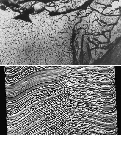
246 Minerals formed by vapor growth
0.1 mm
Figure 12.8. Regular pattern seen in macro-steps on a {0001} face of hematite.
on the glide plane after the cessation of growth. Straight steps of this type are observed only on hematite crystals from particular localities, and are related to the intensity of volcanic activity [8].
Etching occurring after the cessation of growth is well recorded in the form of step patterns on the crystal faces on hematite crystals from the Azores Islands. The {0001} face of hematite from this locality shows step patterns that resemble growth steps, but careful observations indicate that all these steps have a chopping waveform (see Section 5.10 and Fig. 5.18) and that the steps appear due to twodimensional etching starting from growth steps. Figure 12.11 is a surface microtopograph demonstrating this, and it should be noted that there is no elevated center of the step patterns. The circular step patterns seen on the photograph are all depressions.