

Product Guide
4. Description of the Engine
4.Description of the Engine
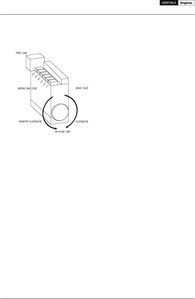
4.1Definitions
Figure 4.1 In-line engine definitions (1V93C0029)
4.2Main components and systems
4.2.1 Engine block
The engine block is a one piece nodular cast iron component with integrated channels for lubricating oil and cooling water.
The main bearing caps are fixed from below by two hydraulically tensioned screws. They are guided sideways by the engine block at the top as well as at the bottom. Hydraulically tightened horizontal side screws at the lower guiding provide a very rigid crankshaft bearing.
4.2.2 Crankshaft
The crankshaft is forged in one piece and mounted on the engine block in an under-slung way.
4.2.3 Connecting rod
The connecting rod is of forged alloy steel. All connecting rod studs are hydraulically tightened. Oil is led to the gudgeon pin bearing and piston through a bore in the connecting rod.
4.2.4 Main bearings and big end bearings
The main bearings and the big end bearings are of the Al based bi-metal type with steel back.
4.2.5 Cylinder liner
The cylinder liners are centrifugally cast of a special grey cast iron alloy developed for good wear resistance and high strength. They are of wet type, sealed against the engine block metallically at the upper part and by O-rings at the lower part. To eliminate the risk of bore polishing the liner is equipped with an anti-polishing ring.
4.2.6 Piston
The piston is of composite design with nodular cast iron skirt and steel crown. The piston skirt is pressure lubricated, which ensures a well-controlled oil flow to the cylinder liner during all operating conditions. Oil
18 |
Product Guide Wärtsilä 20 - 3/2009 |

Product Guide
4. Description of the Engine
is fed through the connecting rod to the cooling spaces of the piston. The piston cooling operates according to the cocktail shaker principle. The piston ring grooves in the piston top are hardened for better wear resistance.
4.2.7 Piston rings
The piston ring set consists of two directional compression rings and one spring-loaded conformable oil scraper ring. All rings are chromium-plated and located in the piston crown.
4.2.8 Cylinder head
The cylinder head is made of grey cast iron. The thermally loaded flame plate is cooled efficiently by cooling water led from the periphery radially towards the centre of the head. The bridges between the valves cooling channels are drilled to provide the best possible heat transfer.
The mechanical load is absorbed by a strong intermediate deck, which together with the upper deck and the side walls form a box section in the four corners of which the hydraulically tightened cylinder head bolts are situated. The exhaust valve seats are directly water-cooled.
All valves are equipped with valve rotators.
4.2.9 Camshaft and valve mechanism
There is one cam piece for each cylinder with separate bearing in between. The drop forged completely hardened camshaft pieces have fixed cams. The camshaft bearing housings are integrated in the engine block casting and are thus completely closed. The camshaft covers, one for each cylinder, seal against the engine block with a closed O-ring profile.
The valve tappets are of piston type with self-adjustment of roller against cam to give an even distribution of the contact pressure. The valve springs ensure that the valve mechanism is dynamically stable.
Variable Inlet valve Closure (VIC), which is available on IMO Tier 2 engines, offers flexibility to apply early inlet valve closure at high load for lowest NOx levels, while good part-load performance is ensured by adjusting the advance to zero at low load.
4.2.10 Camshaft drive
The camshafts are driven by the crankshaft through a gear train.
4.2.11 Turbocharging and charge air cooling
The selected turbo charger offers the ideal combination of high-pressure ratios and good efficiency. The charge air cooler is single stage type and cooled by LT-water.
4.2.12 Fuel injection equipment
The injection pumps are one-cylinder pumps located in the “hot-box”, which has the following functions:
•Housing for the injection pump element
•Fuel supply channel along the whole engine
•Fuel return channel from each injection pump
•Lubricating oil supply to the valve mechanism
•Guiding for the valve tappets
The injection pumps have built-in roller tappets and are through-flow type to enable heavy fuel operation. They are also equipped with a stop cylinder, which is connected to the electro-pneumatic overspeed protection system.
The injection valve is centrally located in the cylinder head and the fuel is admitted sideways through a high pressure connection screwed in the nozzle holder. The injection pipe between the injection pump and the high pressure connection is well protected inside the hot box. The high pressure side of the injection system is completely separated from the hot parts of the exhaust gas components.
Product Guide Wärtsilä 20 - 3/2009 |
19 |

Product Guide
4. Description of the Engine
4.2.13 Exhaust pipes
The complete exhaust gas system is enclosed in an insulated box consisting of easily removable panels. Mineral wool is used as insulating material.
4.2.14 Automation system
Wärtsilä 20 is equipped with a modular embedded automation system, Wärtsilä Unified Controls - UNIC, which is available in two different versions. The basic functionality is the same in both versions, but the functionality can be easily expanded to cover different applications.
UNIC C1 has a completely hardwired signal interface with the external systems, whereas UNIC C2 and has hardwired interface for control functions and a bus communication interface for alarm and monitoring.
All versions have en engine safety module and a local control panel mounted on the engine. The engine safety module handles fundamental safety, for example overspeed and low lubricating oil pressure shutdown. The safety module also performs fault detection on critical signals and alerts the alarm system about detected failures. The local control panel has push buttons for local start/stop and shutdown reset, as well as a display showing the most important operating parameters. Speed control is included in the automation system on the engine (all versions).
The major additional features of UNIC C2 are: all necessary engine control functions are handled by the equipment on the engine, bus communication to external systems and a more comprehensive local display unit.
Conventional heavy duty cables are used on the engine and the number of connectors are minimised. Power supply, bus communication and safety-critical functions are doubled on the engine. All cables to/from external systems are connected to terminals in the main cabinet on the engine.
20 |
Product Guide Wärtsilä 20 - 3/2009 |
Product Guide
4. Description of the Engine
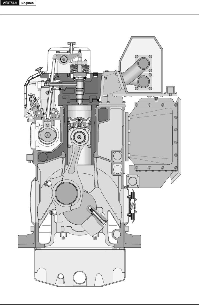
4.3Cross sections of the engine
Figure 4.2 Cross sections of the engine
Product Guide Wärtsilä 20 - 3/2009 |
21 |