


Product Guide
13. Exhaust Emissions
13. Exhaust Emissions
Exhaust emissions from the diesel engine mainly consist of nitrogen, oxygen and combustion products like carbon dioxide (CO2), water vapour and minor quantities of carbon monoxide (CO), sulphur oxides (SOx), nitrogen oxides (NOx), partially reacted and non-combusted hydrocarbons (HC) and particulate matter (PM).
There are different emission control methods depending on the aimed pollutant. These are mainly divided in two categories; primary methods that are applied on the engine itself and secondary methods that are applied on the exhaust gas stream.
13.1 Diesel engine exhaust components
The nitrogen and oxygen in the exhaust gas are the main components of the intake air which don't take part in the combustion process.
CO2 and water are the main combustion products. Secondary combustion products are carbon monoxide, hydrocarbons, nitrogen oxides, sulphur oxides, soot and particulate matters.
In a diesel engine the emission of carbon monoxide and hydrocarbons are low compared to other internal combustion engines, thanks to the high air/fuel ratio in the combustion process. The air excess allows an almost complete combustion of the HC and oxidation of the CO to CO2, hence their quantity in the exhaust gas stream are very low.
13.1.1 Nitrogen oxides (NOx)
The combustion process gives secondary products as Nitrogen oxides. At high temperature the nitrogen, usually inert, react with oxygen to form Nitric oxide (NO) and Nitrogen dioxide (NO2), which are usually grouped together as NOx emissions. Their amount is strictly related to the combustion temperature.
NO can also be formed through oxidation of the nitrogen in fuel and through chemical reactions with fuel radicals. NO in the exhaust gas flow is in a high temperature and high oxygen concentration environment, hence oxidizes rapidly to NO2. The amount of NO2 emissions is approximately 5 % of total NOx emissions.
13.1.2 Sulphur Oxides (SOx)
Sulphur oxides (SOx) are direct result of the sulphur content of the fuel oil. During the combustion process the fuel bound sulphur is rapidly oxidized to sulphur dioxide (SO2). A small fraction of SO2 may be further oxidized to sulphur trioxide (SO3).
13.1.3 Particulate Matter (PM)
The particulate fraction of the exhaust emissions represents a complex mixture of inorganic and organic substances mainly comprising soot (elemental carbon), fuel oil ash (together with sulphates and associated water), nitrates, carbonates and a variety of non or partially combusted hydrocarbon components of the fuel and lubricating oil.
13.1.4 Smoke
Although smoke is usually the visible indication of particulates in the exhaust, the correlations between particulate emissions and smoke is not fixed. The lighter and more volatile hydrocarbons will not be visible nor will the particulates emitted from a well maintained and operated diesel engine.
Smoke can be black, blue, white, yellow or brown in appearance. Black smoke is mainly comprised of carbon particulates (soot). Blue smoke indicates the presence of the products of the incomplete combustion of the fuel or lubricating oil. White smoke is usually condensed water vapour. Yellow smoke is caused by NOx emissions. When the exhaust gas is cooled significantly prior to discharge to the atmosphere, the condensed NO2 component can have a brown appearance.
92 |
Product Guide Wärtsilä 20 - 3/2009 |

Product Guide
13. Exhaust Emissions
13.2 Marine exhaust emissions legislation
13.2.1 International Maritime Organization (IMO)
The increasing concern over the air pollution has resulted in the introduction of exhaust emission controls to the marine industry. To avoid the growth of uncoordinated regulations, the IMO (International Maritime Organization) has developed the Annex VI of MARPOL 73/78, which represents the first set of regulations on the marine exhaust emissions.
MARPOL Annex VI - Air Pollution
The MARPOL 73/78 Annex VI entered into force 19 May 2005, and applies to diesel engines over 130 kW installed on ships built (defined as date of keel laying or similar stage of construction) on or after January 1, 2000. The Annex VI sets limits on Nitrogen Oxides, Sulphur Oxides and Volatile Organic Compounds emissions from ship exhausts and prohibits deliberate emissions of ozone depleting substances.
Nitrogen Oxides, NOx Emissions
IMO Tier 1 NOx emission standard
NOx emissions limit is expressed as dependent on engine speed. IMO has developed a detailed NOx Technical Code which regulates the enforcement of these rules.
The IMO Tier 1 NOx limit is defined as follows:
NOx [g/kWh] |
= 17 when rpm < 130 |
|
= 45 x rpm-0.2 when 130 < rpm < 2000 |
|
= 9.8 when rpm > 2000 |
The NOx level is a weigthed awerage of NOx emissions at different loads, in accordance with the applicable test cycle for the specific engine operating profile.
EIAPP Certification
An EIAPP (Engine International Air Pollution Prevention) Certificate is issued for each engine showing that the engine complies with the NOx regulations set by the IMO.
When testing the engine for NOx emissions, the reference fuel is Marine Diesel Oil (distillate) and the test is performed according to ISO 8178 test cycles. Subsequently, the NOx value has to be calculated using different weighting factors for different loads that have been corrected to ISO 8178 conditions. The used ISO 8178 test cycles are presented in following table.
Table 13.1 ISO 8178 test cycles
D2: Auxiliary engine |
Speed (%) |
100 |
100 |
100 |
100 |
100 |
|
Power (%) |
100 |
75 |
50 |
25 |
10 |
|
Weighting |
0.05 |
0.25 |
0.3 |
0.3 |
0.1 |
|
factor |
|
|
|
|
|
E2: Diesel electric propul- |
Speed (%) |
100 |
100 |
100 |
100 |
|
sion or controllable pitch |
Power (%) |
100 |
75 |
50 |
25 |
|
propeller |
|
|||||
Weighting |
0.2 |
0.5 |
0.15 |
0.15 |
|
|
|
|
|||||
|
factor |
|
|
|
|
|
E3: Fixed pitch propeller |
Speed (%) |
100 |
91 |
80 |
63 |
|
|
Power (%) |
100 |
75 |
50 |
25 |
|
|
Weighting |
0.2 |
0.5 |
0.15 |
0.15 |
|
|
factor |
|
|
|
|
|
Product Guide Wärtsilä 20 - 3/2009 |
93 |

Product Guide
13. Exhaust Emissions
C1: |
Speed |
|
Rated |
|
Intermediate |
|
Idle |
||
"Variable -speed and -load |
Torque (%) |
100 |
75 |
50 |
10 |
100 |
75 |
50 |
0 |
auxiliary engine application" |
Weighting |
0.15 |
0.15 |
0.15 |
0.1 |
0.1 |
0.1 |
0.1 |
0.15 |
|
|||||||||
factor
Engine family/group
As engine manufacturers have a variety of engines ranging in size and application, the NOx Technical Code allows the organising of engines into families or groups. By definition, an engine family is a manufacturer’s grouping, which through their design, are expected to have similar exhaust emissions characteristics i.e., their basic design parameters are common. When testing an engine family, the engine which is expected to develop the worst emissions is selected for testing. The engine family is represented by the parent engine, and the certification emission testing is only necessary for the parent engine. Further engines can be certified by checking document, component, setting etc., which have to show correspondence with those of the parent engine.
Technical file
According to the IMO regulations, a Technical File shall be made for each engine. The Technical File contains information about the components affecting NOx emissions, and each critical component is marked with a special IMO number. The allowable setting values and parameters for running the engine are also specified in the Technical File. The EIAPP certificate is part of the IAPP (International Air Pollution Prevention) Statement of Compliance for the whole ship.
IMO Tier 2 NOx emission standard (new ships 2011)
The Marpol Annex VI and the NOx Technical Code has been undertaken a review with the intention to further reduce emissions from ships. In the IMO BLG 12 meeting in April 2008 proposals for IMO Tier 2 and IMO Tier 3 emission limits were agreed. Final adoption for IMO Tier 2 and Tier 3 was taken by IMO/MEPC 58 in October 2008.
IMO Tier 2 NOx level will enter into force from 1.1.2011 and be applied globally for new marine diesel engines > 130 kW. The IMO Tier 2 NOx limit is expressed as dependent on engine speed.
The IMO Tier 2 NOx limit is defined as follows:
NOx [g/kWh] |
= 44 x rpm-0.23 when 130 < rpm < 2000 |
The NOx level is a weigthed awerage of NOx emissions at different loads, and the test cycle is based on the engine operating profile acconding to ISO 8178 test cycles. IMO Tier 2 NOx limit corresponds to about 20% reduction from todays IMO Tier 1 level. This reduction can be reached with engine optimization.
IMO Tier 3 NOx emission standard (new ships 2016, in designated areas)
IMO Tier 3 NOx level will enter into force from 1 January 2016, but the Tier 3 NOx level will only apply in designated special areas. These areas are not yet defined by IMO. The Tier 3 NOx limit will be applicable to diesel engines > 600 kW and ships with main propulsion engines > 30 litres/cyl. IMO Tier 2 NOx level will apply outside the Tier 3 designated areas. The IMO Tier 3 NOx limit is expressed as dependent on engine speed.
The IMO Tier 3 NOx limit is defined as follows:
NOx [g/kWh] |
= 9 x rpm-0.2 when 130 < rpm < 2000 |
IMO Tier 3 NOx limit corresponds to 80% reduction from todays IMO Tier 1 level. The reduction can be reached by applying a secondary emission control system. At present SCR is the only efficient way to reach the NOx reduction of 80%.
94 |
Product Guide Wärtsilä 20 - 3/2009 |
Product Guide
13. Exhaust Emissions
Figure 13.1 IMO NOx emission limits
Sulphur Oxides, SOx emissions
Marpol Annex VI has set a maximum global sulphur limit of 4,5% in weight for any fuel used on board a ship. Annex VI also contains provisions allowing for special SOx Emission Control Areas (SECA) to be established with more stringent controls on sulphur emissions. In a “SOx Emission Control Area”, which currently comprises the Baltic Sea, the North Sea and the English Channel, the sulphur content of fuel oil used onboard a ship must not exceed 1.5% in weigth. Alternatively, an exhaust gas cleaning system can be applied to reduce the total emission of sulphur oxides from ships, including both auxiliary and main propulsion engines, to 6.0 g/kWh or less calculated as the total weight of sulphur dioxide emission.
The Marpol Annex VI has undertaken a review with the intention to further reduce emissions from ships. In the IMO BLG 12 meeting in April 2008 proposals for new fuel oil sulpur limits were agreed. Final adoption of the proposed sulphur limits was taken by IMO/MEPC 58 in October 2008. The upcoming limits for future fuel oil sulpur contents are presented in the following table.
Table 13.2 Upcoming fuel sulphur caps |
|
|
|
Fuel sulphur cap |
Area |
Date of implementation |
|
Max. 1% S in fuel |
SECA Areas |
1 |
July 2010 |
Max 3.5% S in fuel |
Globally |
1 |
January 2012 |
Max. 0.1% S in fuel |
SECA Areas |
1 |
January 2015 |
Max. 0.5% S in fuel |
Globally |
1 |
January 2020 |
Abatement technologies including scrubbers are allowed as alternatives to low sulphur fuels.
13.2.2 Other Legislations
There are also other local legislations in force in particular regions.
13.3 Methods to reduce exhaust emissions
AllstandardWärtsiläenginesmeettheNOxemissionlevelsetbytheIMO(InternationalMaritimeOrganisation) and most of the local emission levels without any modifications. Wärtsilä has also developed solutions to significantly reduce NOx emissions when this is required.
Diesel engine exhaust emissions can be reduced either with primary or secondary methods. The primary methods limit the formation of specific emissions during the combustion process. The secondary methods reduce emission components after formation as they pass through the exhaust gas system.
Product Guide Wärtsilä 20 - 3/2009 |
95 |
Product Guide
13. Exhaust Emissions
13.3.1 Selective Catalytic Reduction (SCR)
Selective Catalytic Reduction (SCR) is the only way to reach a NOx reduction level of 85-95%. The disadvantages of the SCR are the large size and the relatively high installation and operation costs.
A reducing agent, aqueous solution of urea (40 wt-%), is injected into the exhaust gas directly after the turbocharger. Urea decays rapidly to ammonia (NH3) and carbon dioxide. The mixture is passed through the catalyst where NOx is converted to harmless nitrogen and water.
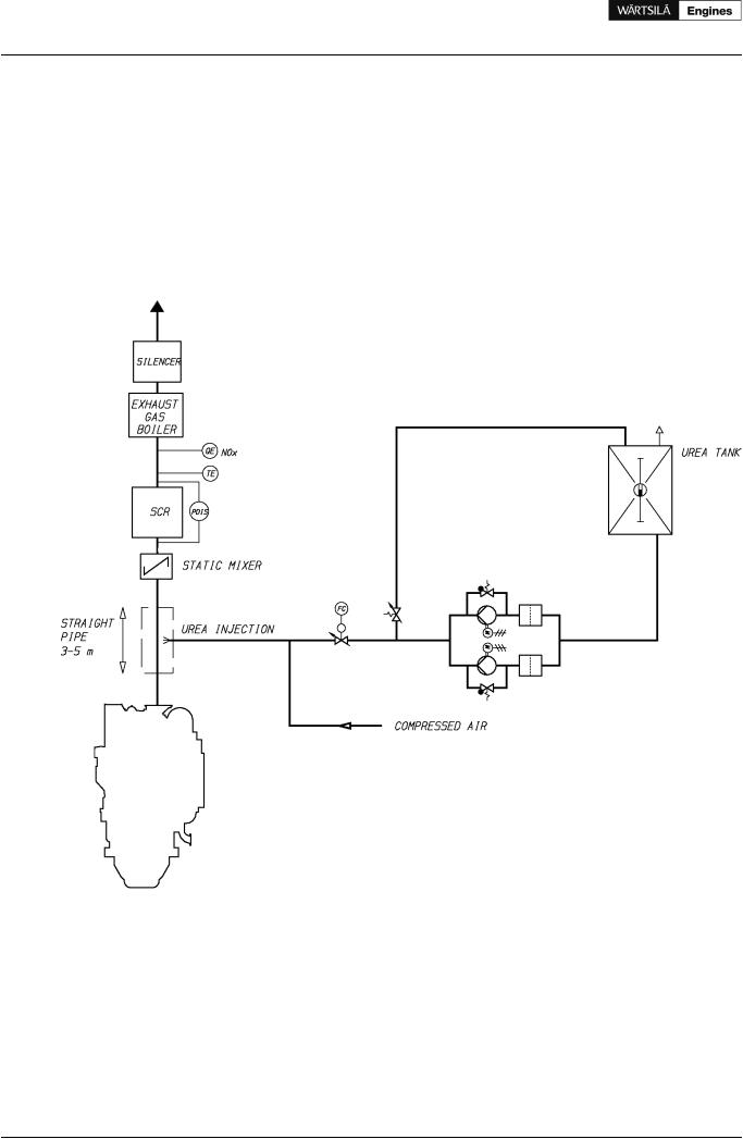
A typical SCR system comprises a urea solution storage tank, a urea solution pumping system, a reducing agent injection system and the catalyst housing with catalyst elements. In the next figure a typical SCR system is shown.
Figure 13.2 Typical P&ID for SCR system
The catalyst elements are of honeycomb type and are typically of a ceramic structure with the active catalytic material spread over the catalyst surface. The catalyst elements are arranged in layers and a soot blowing system should provided before each layer in order to avoid catalyst clogging.
The injection of urea is controlled by feedback from a NOx measuring device after the catalyst. The rate of NOx reduction depends on the amount of urea added, which can be expressed as NH3/NOx ratio. The increase of the catalyst volume can also increase the reduction rate.
When operating on HFO, the exhaust gas temperature before the SCR must be at least 330°C, depending on the sulphur content of the fuel. When operating on MDF, the exhaust gas temperature can be lower. If an exhaust gas boiler is specified, it should be installed after the SCR.
The lifetime of the catalyst is mainly dependent on the fuel oil quality and also to some extent on the lubricating oil quality. The lifetime of a catalyst is typically 3-5 years for liquid fuels and slightly longer if the engine
96 |
Product Guide Wärtsilä 20 - 3/2009 |

Product Guide
13. Exhaust Emissions
is operating on gas. The total catalyst volume is usually divided into three layers of catalyst, and thus one layer at time can be replaced, and remaining activity in the older layers can be utilised.
Urea consumption and replacement of catalyst layers are generating the main running costs of the catalyst. The urea consumption is about 15 g/kWh of 40 wt-% urea. The urea solution can be prepared mixing urea granulates with water or the urea can be purchased as a 40 wt-% solution. The urea tank should be big enough for the ship to achieve the required autonomy.
Product Guide Wärtsilä 20 - 3/2009 |
97 |