

Product Guide
10. Combustion Air System
10. Combustion Air System
10.1 Engine room ventilation
To maintain acceptable operating conditions for the engines and to ensure trouble free operation of all equipment, attention shall be paid to the engine room ventilation and the supply of combustion air.
The air intakes to the engine room must be located and designed so that water spray, rain water, dust and exhaust gases cannot enter the ventilation ducts and the engine room.
The dimensioning of blowers and extractors should ensure that an overpressure of about 50 Pa is maintained in the engine room in all running conditions.
For the minimum requirements concerning the engine room ventilation and more details, see applicable standards, such as ISO 8861.
The amount of air required for ventilation is calculated from the total heat emission Φ to evacuate. To determine Φ, all heat sources shall be considered, e.g.:
•Main and auxiliary diesel engines
•Exhaust gas piping
•Generators
•Electric appliances and lighting
•Boilers
•Steam and condensate piping
•Tanks
It is recommended to consider an outside air temperature of no less than 35°C and a temperature rise of 11°C for the ventilation air.
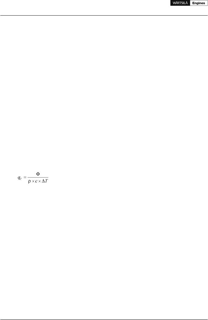
The amount of air required for ventilation is then calculated using the formula:
where:
qv = air flow [m³/s]
Φ = total heat emission to be evacuated [kW]
ρ = air density 1.13 kg/m³
c = specific heat capacity of the ventilation air 1.01 kJ/kgK T = temperature rise in the engine room [°C]
The heat emitted by the engine is listed in chapter Technical data.
The engine room ventilation air has to be provided by separate ventilation fans. These fans should preferably have two-speed electric motors (or variable speed). The ventilation can then be reduced according to outside air temperature and heat generation in the engine room, for example during overhaul of the main engine when it is not preheated (and therefore not heating the room).
The ventilation air is to be equally distributed in the engine room considering air flows from points of delivery towards the exits. This is usually done so that the funnel serves as exit for most of the air. To avoid stagnant air, extractors can be used.
It is good practice to provide areas with significant heat sources, such as separator rooms with their own air supply and extractors.
Under-cooling of the engine room should be avoided during all conditions (service conditions, slow steaming and in port). Cold draft in the engine room should also be avoided, especially in areas of frequent maintenance activities. For very cold conditions a pre-heater in the system should be considered. Suitable media could be thermal oil or water/glycol to avoid the risk for freezing. If steam is specified as heating medium for the ship, the pre-heater should be in a secondary circuit.
80 |
Product Guide Wärtsilä 20 - 3/2009 |
Product Guide
10. Combustion Air System
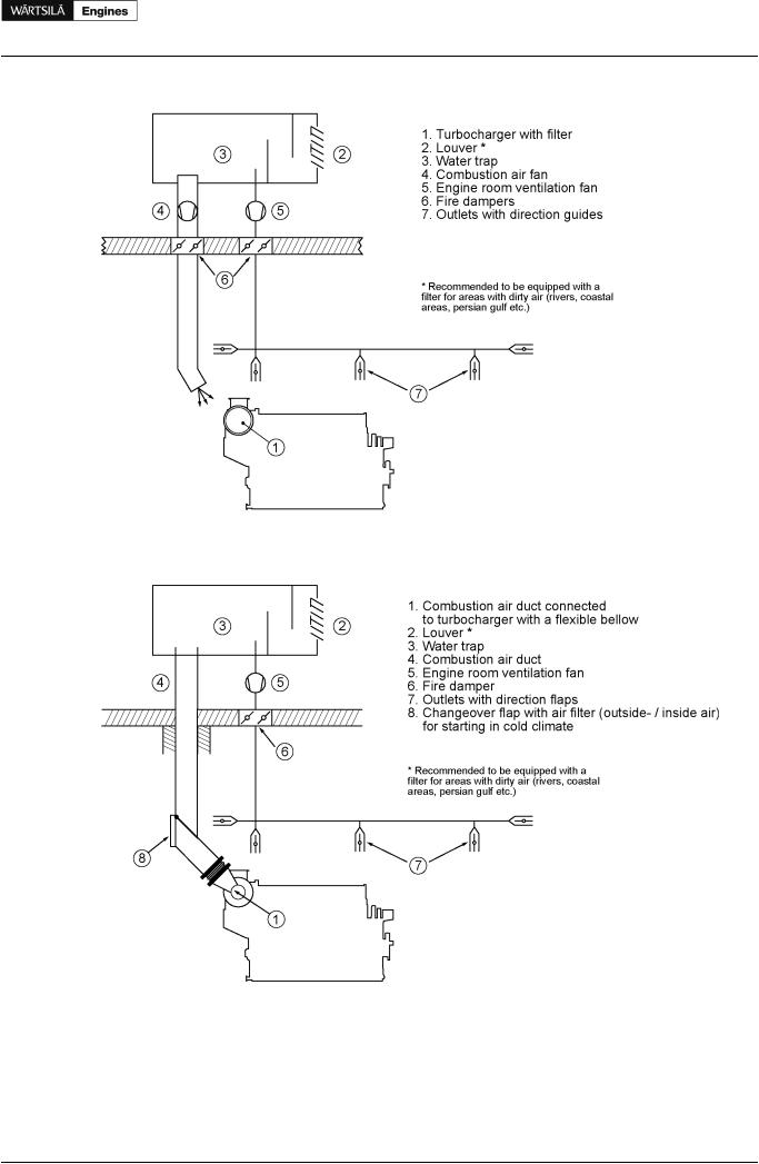
Figure 10.1 Engine room ventilation, turbocharger with air filter (DAAE092651)
Figure 10.2 Engine room ventilation, air duct connected to the turbocharger (DAAE092652)
10.2 Combustion air system design
Usually, the combustion air is taken from the engine room through a filter on the turbocharger. This reduces the risk for too low temperatures and contamination of the combustion air. It is important that the combustion air is free from sea water, dust, fumes, etc.
Product Guide Wärtsilä 20 - 3/2009 |
81 |

Product Guide
10. Combustion Air System
During normal operating conditions the air temperature at turbocharger inlet should be kept between 15...35°C. Temporarily max. 45°C is allowed. For the required amount of combustion air, see section
Technical data.
The combustion air shall be supplied by separate combustion air fans, with a capacity slightly higher than the maximum air consumption. The combustion air mass flow stated in technical data is defined for an ambient air temperature of 25°C. Calculate with an air density corresponding to 30°C or more when translating the mass flow into volume flow. The expression below can be used to calculate the volume flow.
where:
qc = combustion air volume flow [m³/s] m' = combustion air mass flow [kg/s]
ρ = air density 1.15 kg/m³
The fans should preferably have two-speed electric motors (or variable speed) for enhanced flexibility. In addition to manual control, the fan speed can be controlled by engine load.
In multi-engine installations each main engine should preferably have its own combustion air fan. Thus the air flow can be adapted to the number of engines in operation.
The combustion air should be delivered through a dedicated duct close to the turbocharger, directed towards the turbocharger air intake. The outlet of the duct should be equipped with a flap for controlling the direction and amount of air. Also other combustion air consumers, for example other engines, gas turbines and boilers shall be served by dedicated combustion air ducts.
If necessary, the combustion air duct can be connected directly to the turbocharger with a flexible connection piece. With this arrangement an external filter must be installed in the duct to protect the turbocharger and prevent fouling of the charge air cooler. The permissible total pressure drop in the duct is max. 1.5 kPa. The duct should be provided with a step-less change-over flap to take the air from the engine room or from outside depending on engine load and air temperature.
For very cold conditions heating of the supply air must be arranged. The combustion air fan is stopped during start of the engine and the necessary combustion air is drawn from the engine room. After start either the ventilation air supply, or the combustion air supply, or both in combination must be able to maintain the minimum required combustion air temperature. The air supply from the combustion air fan is to be directed away from the engine, when the intake air is cold, so that the air is allowed to heat up in the engine room.
10.2.1 Charge air shut-off valve, "rigsaver" (optional)
In installations where it is possible that the combustion air includes combustible gas or vapour the engines can be equipped with charge air shut-off valve. This is regulated mandatory where ingestion of flammable gas or fume is possible.
10.2.2 Condensation in charge air coolers
Air humidity may condense in the charge air cooler, especially in tropical conditions. The engine equipped with a small drain pipe from the charge air cooler for condensed water.
The amount of condensed water can be estimated with the diagram below.
82 |
Product Guide Wärtsilä 20 - 3/2009 |
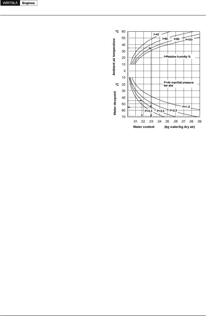
Example, according to the diagram:
At an ambient air temperature of 35°C and a relative humidity of 80%, the content of water in the air is 0.029 kg water/ kg dry air. If the air manifold pressure (receiver pressure) under these conditions is 2.5 bar (= 3.5 bar absolute), the dew point will be 55°C. If the air temperature in the air manifold is only 45°C, the air can only contain 0.018 kg/kg. The difference, 0.011 kg/kg (0.029 - 0.018) will appear as condensed water.
Product Guide Wärtsilä 20 - 3/2009
Product Guide
10. Combustion Air System
Figure 10.3 Condensation in charge air coolers
83