

Product Guide
1. Main Data and Outputs
1.Main Data and Outputs
The Wärtsilä 20 is a 4-stroke, non-reversible, turbocharged and intercooled diesel engine with direct injection of fuel.
Cylinder bore ................................................. |
200 mm |
Stroke ............................................................ |
280 mm |
Piston displacement ...................................... |
8.8 l/cyl |
Number of valves ........................................... |
2 inlet valves and 2 exhaust valves |
Cylinder configuration ................................... |
4, 6, 8, 9, in-line |
Direction of rotation ....................................... |
Clockwise, counterclockwise on request |
Speed ............................................................ |
900, 1000 rpm |
Mean piston speed ........................................ |
8.4, 9.3 m/s |
1.1Maximum continuous output
Table 1.1 Rating table for Wärtsilä 20 |
|
|
|
|
||
Cylinder |
Main engines |
|
Generating sets |
|
||
configuration |
1000 rpm |
900 rpm / 60 Hz |
1000 rpm / 50 Hz |
|||
|
||||||
|
kW |
bhp |
Engine [kW] |
Generator [kVA] |
Engine [kW] |
Generator [kVA] |
W 4L20 |
800 |
1080 |
740 |
880 |
800 |
950 |
W 6L20 |
1200 |
1630 |
1110 |
1320 |
1200 |
1420 |
W 8L20 |
1600 |
2170 |
1480 |
1760 |
1600 |
1900 |
W 9L20 |
1800 |
2440 |
1665 |
1980 |
1800 |
2140 |
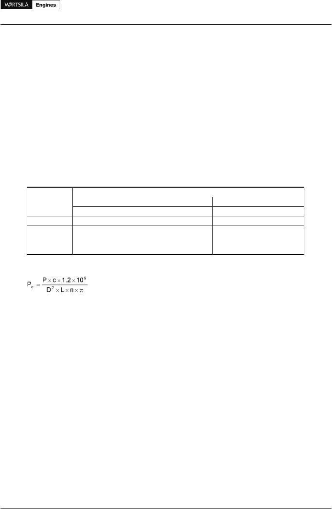
The mean effective pressure pe can be calculated as follows:
where: |
|
Pe = |
Mean effective pressure [bar] |
P = |
Output per cylinder [kW] |
n = |
Engine speed [r/min] |
D = |
Cylinder diameter [mm] |
L = |
Length of piston stroke [mm] |
c = |
Operating cycle (4) |
Product Guide Wärtsilä 20 - 3/2009 |
1 |

Product Guide
1. Main Data and Outputs
1.2Reference conditions
The output is available up to a charge air coolant temperature of max. 38°C and an air temperature of max. 45°C. For higher temperatures, the output has to be reduced according to the formula stated in ISO 3046- 1:2002 (E).
The specific fuel oil consumption is stated in the chapter Technical data. The stated specific fuel oil consumption applies to engines without engine driven pumps, operating in ambient conditions according to ISO 15550:2002 (E). The ISO standard reference conditions are:
total barometric pressure |
100 kPa |
air temperature |
25°C |
relative humidity |
30% |
charge air coolant temperature |
25°C |
Correction factors for the fuel oil consumption in other ambient conditions are given in standard ISO 3046- 1:2002.
1.3Operation in inclined position
Max. inclination angles at which the engine will operate satisfactorily.
Transverse inclination, permanent (list) .................. |
15° |
Transverse inclination, momentary (roll) ................. |
22.5° |
Longitudinal inclination, permanent (trim) ............... |
10° |
Longitudinal inclination, momentary (pitch) ............ |
10° |
2 |
Product Guide Wärtsilä 20 - 3/2009 |

Product Guide
1. Main Data and Outputs
1.4Dimensions and weights
Figure 1.1 Main engines (3V92E0068c)
Engine |
A* |
A |
B* |
B |
C* |
C |
D |
E |
F1 |
F2 |
H |
H |
I |
K |
W 4L20 |
|
2510 |
|
1348 |
|
1483 |
1800 |
325 |
725 |
725 |
1480 |
155 |
718 |
980 |
W 6L20 |
3292 |
3108 |
1528 |
1348 |
1580 |
1579 |
1800 |
325 |
624 |
824 |
2080 |
155 |
718 |
980 |
W 8L20 |
4011 |
3783 |
1614 |
1465 |
1756 |
1713 |
1800 |
325 |
624 |
824 |
2680 |
155 |
718 |
980 |
W 9L20 |
4299 |
4076 |
1614 |
1449 |
1756 |
1713 |
1800 |
325 |
624 |
824 |
2980 |
155 |
718 |
980 |
F1 for dry sump and F2 for deep wet sump |
|
|
|
|
|
|
|
|
|
|
|
|||
Engine |
M* |
M |
N* |
N |
P* |
P |
R* |
R |
S* |
S |
T* |
T |
Weight |
W 4L20 |
|
854 |
|
665 |
|
920 |
|
248 |
|
694 |
|
349 |
7.2 |
W 6L20 |
951 |
950 |
589 |
663 |
1200 |
971 |
328 |
328 |
762 |
763 |
266 |
343 |
9.3 |
W 8L20 |
1127 |
1084 |
708 |
738 |
1224 |
1000 |
390 |
390 |
907 |
863 |
329 |
339 |
11.0 |
W 9L20 |
1127 |
1084 |
696 |
731 |
1224 |
1000 |
390 |
390 |
907 |
863 |
329 |
339 |
11.6 |
* Turbocharger at flywheel end Dimensions in mm. Weight in tons.
Product Guide Wärtsilä 20 - 3/2009 |
3 |

Product Guide
1. Main Data and Outputs
Figure 1.2 Generating sets (3V58E0576d)
Engine |
A* |
B |
C* |
D* |
E* |
F* |
G* |
H* |
I |
K* |
L* |
M |
Weight * |
W 4L20 |
4910 |
665 |
4050 |
2460 |
725 |
990 |
1270/1420 |
1770/1920 |
1800 |
1580/1730 |
2338 |
1168 |
14.0 |
W 6L20 |
5325 |
663 |
4575 |
2300 |
725 |
895/975/1025 |
1270/1420/1570 |
1770/1920/2070 |
1800 |
1580/1730/1880 |
2243/2323/2373 |
1299 |
16.8 |
W 8L20 |
6030 |
731 |
5100 |
2310 |
725 |
1025/1075 |
1420/1570 |
1920/2070 |
1800 |
1730/1880 |
2474/2524 |
1390 |
20.7 |
W 9L20 |
6535 |
731 |
5400 |
2580 |
725 |
1075/1125 |
1570/1800 |
2070/2300 |
1800 |
1880/2110 |
2524/2574 |
1390 |
23.8 |
* Dependent on generator type and size. Dimensions in mm. Weight in tons.
4 |
Product Guide Wärtsilä 20 - 3/2009 |