- •Introduction
- •Table of Contents
- •1. Main Data and Outputs
- •1.1 Maximum continuous output
- •1.2 Reference conditions
- •1.3 Operation in inclined position
- •1.4 Dimensions and weights
- •2. Operating ranges
- •2.1 Engine operating range
- •2.2 Loading capacity
- •2.3 Low air temperature
- •2.4 Operation at low load and idling
- •3. Technical Data
- •3.1 Wärtsilä 4L20
- •3.2 Wärtsilä 6L20
- •3.3 Wärtsilä 8L20
- •3.4 Wärtsilä 9L20
- •4. Description of the Engine
- •4.1 Definitions
- •4.2 Main components and systems
- •4.3 Cross sections of the engine
- •4.4 Overhaul intervals and expected lifetimes
- •5. Piping Design, Treatment and Installation
- •5.1 Pipe dimensions
- •5.2 Trace heating
- •5.3 Operating and design pressure
- •5.4 Pipe class
- •5.5 Insulation
- •5.6 Local gauges
- •5.7 Cleaning procedures
- •5.8 Flexible pipe connections
- •5.9 Clamping of pipes
- •6. Fuel Oil System
- •6.1 Acceptable fuel characteristics
- •6.2 Internal fuel oil system
- •6.3 External fuel oil system
- •7. Lubricating Oil System
- •7.1 Lubricating oil requirements
- •7.2 Internal lubricating oil system
- •7.3 External lubricating oil system
- •7.4 Crankcase ventilation system
- •7.5 Flushing instructions
- •8. Compressed Air System
- •8.1 Internal compressed air system
- •8.2 External compressed air system
- •9. Cooling Water System
- •9.1 Water quality
- •9.2 Internal cooling water system
- •9.3 External cooling water system
- •10. Combustion Air System
- •10.1 Engine room ventilation
- •10.2 Combustion air system design
- •11. Exhaust Gas System
- •11.1 Internal exhaust gas system
- •11.2 Exhaust gas outlet
- •11.3 External exhaust gas system
- •12. Turbocharger Cleaning
- •12.1 Turbine cleaning system
- •12.2 Compressor cleaning system
- •13. Exhaust Emissions
- •13.1 Diesel engine exhaust components
- •13.2 Marine exhaust emissions legislation
- •13.3 Methods to reduce exhaust emissions
- •14. Automation System
- •14.1 UNIC C1
- •14.2 UNIC C2
- •14.3 Functions
- •14.4 Alarm and monitoring signals
- •14.5 Electrical consumers
- •15. Foundation
- •15.1 Steel structure design
- •15.2 Mounting of main engines
- •15.3 Mounting of generating sets
- •15.4 Flexible pipe connections
- •16. Vibration and Noise
- •16.1 External forces and couples
- •16.2 Mass moments of inertia
- •16.3 Structure borne noise
- •16.4 Air borne noise
- •17. Power Transmission
- •17.1 Flexible coupling
- •17.2 Clutch
- •17.3 Shaft locking device
- •17.4 Power-take-off from the free end
- •17.5 Input data for torsional vibration calculations
- •17.6 Turning gear
- •18. Engine Room Layout
- •18.1 Crankshaft distances
- •18.2 Space requirements for maintenance
- •18.3 Transportation and storage of spare parts and tools
- •18.4 Required deck area for service work
- •19. Transport Dimensions and Weights
- •19.1 Lifting of engines
- •19.2 Engine components
- •20. Product Guide Attachments
- •21. ANNEX
- •21.1 Unit conversion tables
- •21.2 Collection of drawing symbols used in drawings
Product Guide
12. Turbocharger Cleaning
Regular water cleaning of the turbine and the compressor reduces the formation of deposits and extends the time between overhauls. Fresh water is injected into the turbocharger during operation. Additives, solvents or salt water must not be used and the cleaning instructions in the operation manual must be carefully followed.
12.1 Turbine cleaning system
A dosing unit consisting of a flow meter and an adjustable throttle valve is delivered for each installation. The dosing unit is installed in the engine room and connected to the engine with a detachable rubber hose. The rubber hose is connected with quick couplings and the length of the hose is normally 10 m. One dosing unit can be used for several engines.
Water supply: |
|
Fresh water |
|
Min. pressure |
0.3 MPa (3 bar) |
Max. pressure |
2 MPa (20 bar) |
Max. temperature |
80 °C |
Flow |
6-10 l/min (depending on cylinder configuration) |
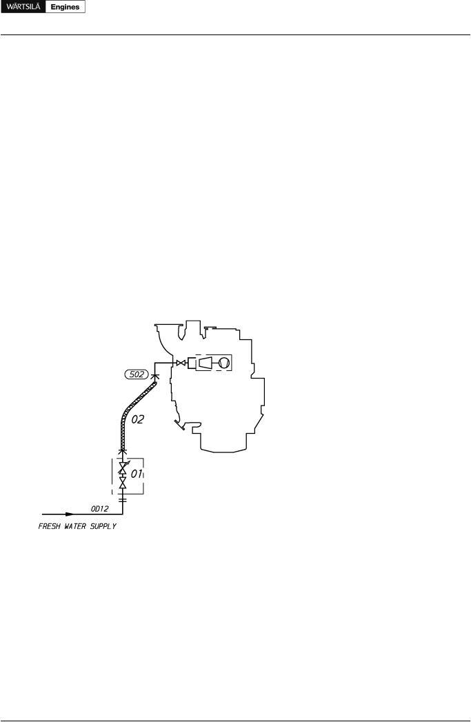
Figure 12.1 Turbine cleaning system (DAAE003884)
System components |
Pipe connections |
Size |
01 Dosing unit with shut-off valve |
502 Cleaning water to turbine |
Quick coupling |
02Rubber hose
12.2Compressor cleaning system
The compressor side of the turbocharger is cleaned using a separate dosing vessel mounted on the engine.
Product Guide Wärtsilä 20 - 3/2009 |
91 |