

Product Guide
14. Automation System
14. Automation System
Wärtsilä Unified Controls – UNIC is a modular embedded automation system, which is available in two different versions.
The basic functionality is the same in both versions. UNIC C1 has a completely hardwired signal interface with external systems, whereas UNIC C2 has a hardwired interface for control functions and a bus communication interface for alarm and monitoring.
14.1 UNIC C1
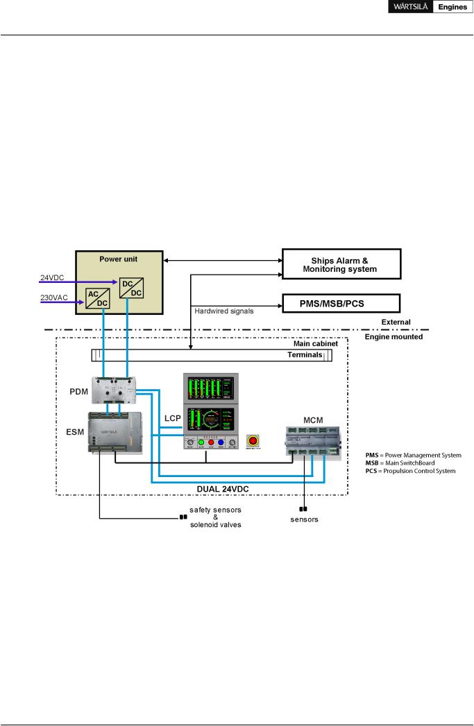
The equipment on the engine included in UNIC C1 handles all control functions on the engine; for example start sequencing, start blocking, normal stops, safety shutdowns, speed control and power distribution. The engine is equipped with push buttons for local operation and local display of the most important operating parameters. All terminals for signals to/from external systems are located in the main cabinet on the engine.
Figure 14.1 Architecture of UNIC C1
Equipment in the main cabinet on the engine:
MCM |
Main Control Module handles all strategic control functions, for example start sequencing, start |
|
blocking and speed/load control. |
ESM |
Engine Safety Module handles fundamental engine safety, for example shutdown due to overspeed |
|
or low lubricating oil pressure. The safety module is the interface to the shutdown devices on the |
|
engine for all other control equipment. |
LCP |
Local Control Panel is equipped with push buttons and switches for local engine control, as well as |
|
a graphical panel with indication of the most important operating parameters. |
PDM |
PowerDistributionModulehandlesfusing,powerdistribution,earthfaultmonitoringandEMCfiltration |
|
in the system. It provides two fully redundant 24 VDC supplies to all modules, sensors and control |
|
devices. |
98 |
Product Guide Wärtsilä 20 - 3/2009 |

Product Guide
14. Automation System
Equipment locally on the engine
•Sensors
•Solenoids
•Actuators
The above equipment is prewired to the main cabinet on the engine. The ingress protection class is IP54.
External equipment
Power unit
Two redundant power supply converters/isolators are installed in a steel sheet cabinet for bulkhead mounting, protection class IP44.
14.1.1 Local control panel (LCP)
Figure 14.2 Local control panel
Operational functions available at the LCP:
•Local start
•Local stop
•Local emergency stop
•Local shutdown reset
•Exhaust gas temperature selector switch
Product Guide Wärtsilä 20 - 3/2009 |
99 |

Product Guide
14.Automation System
•Local mode selector switch with positions: blow, blocked, local and remote.
-Local: Engine start and stop can be done only at the local control panel.
-Remote: Engine can be started and stopped only remotely.
-Blow: In this position it is possible to perform a “blow” (an engine rotation check with indicator valves open and disabled fuel injection) by the start button.
-Blocked: Normal start of the engine is inhibited.
Parameters indicated at the LCP
•Engine speed
•Turbocharger speed
•Running hours
•Fuel oil pressure
•Lubricating oil pressure
•Starting air pressure
•Control air pressure
•Charge air pressure
•LT cooling water pressure
•HT cooling water pressure
•HT cooling water temperature
•Exhaust gas temperature after each cylinder, before and after the turbocharger
14.1.2Engine safety system
The engine safety system is based on hardwired logic with redundant design for safety-critical functions. The engine safety module handles fundamental safety functions, for example overspeed protection. It is also the interface to the shutdown devices on the engine for all other parts of the control system.
Main features:
•Redundant design for power supply, speed inputs and shutdown solenoid control
•Fault detection on sensors, solenoids and wires
•Led indication of status and detected faults
•Digital status outputs
•Shutdown latching and reset
•Shutdown pre-warning
•Shutdown override (configuration depending on application)
•Analogue outputs for engine speed and turbocharger speed
•Adjustable speed switches
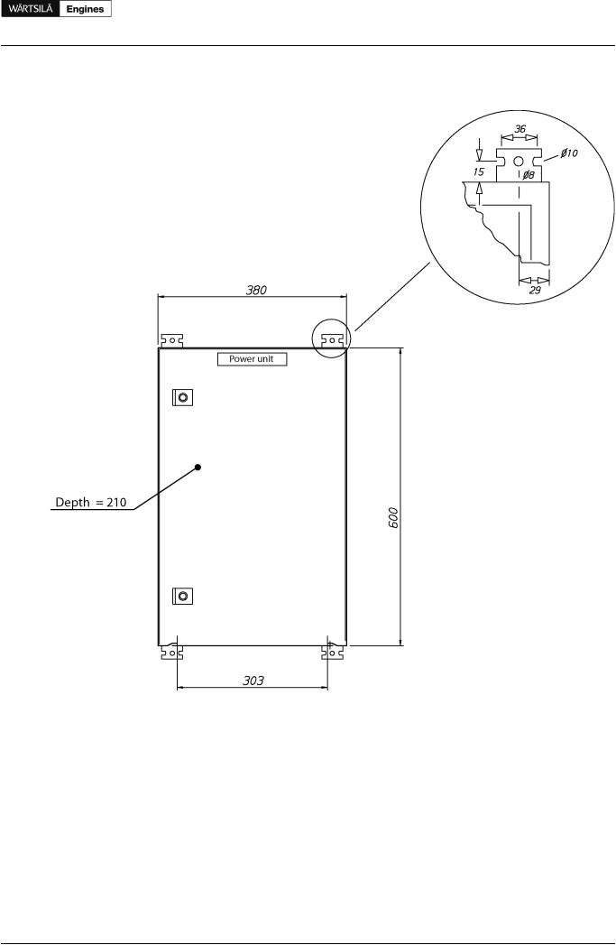
14.1.3Power unit
A power unit is delivered with each engine for separate installation. The power unit supplies DC power to the electrical system on the engine and provides isolation from other DC systems onboard. The cabinet is designed for bulkhead mounting, protection degree IP44, max. ambient temperature 50 °C.
The power unit contains redundant power converters, each converter dimensioned for 100% load. At least one of the two incoming supplies must be connected to a UPS. The power unit supplies the equipment on the engine with 2 x 24 VDC.
Power supply from ship's system:
•Supply 1: 230 VAC / abt. 150 W
100 |
Product Guide Wärtsilä 20 - 3/2009 |
Product Guide
14. Automation System
•Supply 2: 24 VDC / abt. 150 W.
Figure 14.3 Power unit
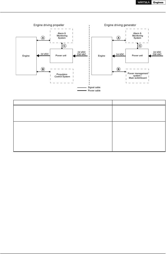
14.1.4 Cabling and system overview
The following figure and table show typical systemand cable interface overview for the engine in mechanical propulsion and generating set applications.
Product Guide Wärtsilä 20 - 3/2009 |
101 |
Product Guide
14. Automation System
Figure 14.4 UNIC C1 overview
Table 14.1 Typical amount of cables for UNIC C1 |
|
|
Cable |
From <=> To |
Cable types (typical) |
A |
Engine <=> alarm & monitoring system |
11 x 2 x 0.75 mm2 |
|
|
9 x 2 x 0.75 mm2 |
|
|
32 x 0.75 mm2 |
|
|
22 x 0.75 mm2 |
B |
Engine <=> propulsion control system |
1 x 2 x 0.75 mm2 |
|
Engine <=> power management system / main switchboard |
1 x 2 x 0.75 mm2 |
|
|
1 x 2 x 0.75 mm2 |
|
|
14 x 0.75 mm2 |
|
|
10 x 0.75 mm2 |
C |
Power unit <=> alarm & monitoring system |
1 x 2 x 0.75 mm2 |
D |
Engine <=> power unit |
4 x 2.5 mm2 (power supply) |
NOTE! |
Cable types and grouping of signals in different cables will differ depending on installation and |
|
|
cylinder configuration. |
|
Power supply requirements are specified in section Power unit
102 |
Product Guide Wärtsilä 20 - 3/2009 |

Product Guide
14. Automation System
Figure 14.5 Signal overview (Main engine)
Figure 14.6 Signal overview (Generating set)
Product Guide Wärtsilä 20 - 3/2009 |
103 |