


Product Guide
6. Fuel Oil System
6.2Internal fuel oil system
Figure 6.1 Internal fuel system, MDF (DAAE060385a)
System components: |
|
|
|
01 |
Injection pump |
04 |
Duplex fine filter |
02 |
Injection valve |
05 |
Engine driven fuel feed pump |
03 |
Fuel leakage collector |
06 |
Pressure regulating valve |
Sensors and indicators:
PT101 Fuel oil pressure, engine inlet PS110 Stand-by pump switch LS103A Fuel oil leakage, injection pipe
PDS113 Fuel oil filter, press. diff. switch (option) TE101 Fuel oil temperature, engine inlet
Pipe connections |
Size |
Pressure class |
Standard |
|
101 |
Fuel inlet |
OD28 |
PN100 |
DIN 2353 |
102 |
Fuel outlet |
OD28 |
PN100 |
DIN 2353 |
103 |
Leak fuel drain, clean fuel |
OD18 |
- |
ISO 3304 |
1041 |
Leak fuel drain, dirty fuel |
OD22 |
- |
ISO 3304 |
1043 |
Leak fuel drain, dirty fuel |
OD18 |
- |
ISO 3304 |
105 |
Fuel stand-by connection |
OD22 |
PN160 |
DIN 2353 |
34 |
Product Guide Wärtsilä 20 - 3/2009 |
Product Guide
6. Fuel Oil System
Figure 6.2 Internal fuel system, HFO (DAAE060384a)
System components: |
|
|
|
01 |
Injection pump |
04 |
Adjustable throttle valve |
02 |
Injection valve |
05 |
Pulse dampers |
03 |
Level alarm for leak fuel oil from injection pipes |
|
|
Sensors and indicators:
PT101 Fuel oil pressure, engine inlet LS103A Fuel oil leakage, injection pipe
TI101 Fuel oil temperature, engine inlet TE101 Fuel oil temperature, engine inlet
Pipe connections |
Size |
Pressure class |
Standard |
|
101 |
Fuel inlet |
OD18 |
PN160 |
DIN 2353 |
102 |
Fuel outlet |
OD18 |
PN160 |
DIN 2353 |
103 |
Leak fuel drain, clean fuel |
OD18 |
- |
ISO 3304 |
1041 |
Leak fuel drain, dirty fuel |
OD22 |
- |
ISO 3304 |
1043 |
Leak fuel drain, dirty fuel |
OD18 |
- |
ISO 3304 |
The engine can be specified to either operate on heavy fuel oil (HFO) or on marine diesel fuel (MDF). The engine is designed for continuous operation on HFO. It is however possible to operate HFO engines on MDF intermittently without alternations. If the operation of the engine is changed from HFO to continuous operation on MDF, then a change of exhaust valves from Nimonic to Stellite is recommended.
HFO engines are equipped with an adjustable throttle valve in the fuel return line on the engine. For engines installed in the same fuel feed circuit, it is essential to distribute the fuel correctly to the engines. For this purpose the pressure drop differences around engines shall be compensated with the adjustable throttle valve.
MDF engines, with an engine driven fuel feed pump, are equipped with a pressure control valve in the fuel return line on the engine. This pressure control valve maintains desired pressure before the injection pumps.
Product Guide Wärtsilä 20 - 3/2009 |
35 |

Product Guide
6. Fuel Oil System
6.2.1 Leak fuel system
Clean leak fuel from the injection valves and the injection pumps is collected on the engine and drained by gravity through a clean leak fuel connection. The clean leak fuel can be re-used without separation. The quantity of clean leak fuel is given in chapter Technical data.
Other possible leak fuel and spilled water and oil is separately drained from the hot-box through dirty fuel oil connections and it shall be led to a sludge tank.
6.3External fuel oil system
The design of the external fuel system may vary from ship to ship, but every system should provide well cleaned fuel of correct viscosity and pressure to each engine. Temperature control is required to maintain stable and correct viscosity of the fuel before the injection pumps (see Technical data). Sufficient circulation through every engine connected to the same circuit must be ensured in all operating conditions.
The fuel treatment system should comprise at least one settling tank and two separators. Correct dimensioning of HFO separators is of greatest importance, and therefore the recommendations of the separator manufacturer must be closely followed. Poorly centrifuged fuel is harmful to the engine and a high content of water may also damage the fuel feed system.
Injection pumps generate pressure pulses into the fuel feed and return piping. The fuel pipes between the feed unit and the engine must be properly clamped to rigid structures. The distance between the fixing points should be at close distance next to the engine. See chapter Piping design, treatment and installation.
A connection for compressed air should be provided before the engine, together with a drain from the fuel return line to the clean leakage fuel or overflow tank. With this arrangement it is possible to blow out fuel from the engine prior to maintenance work, to avoid spilling.
NOTE! In multiple engine installations, where several engines are connected to the same fuel feed circuit, it must be possible to close the fuel supply and return lines connected to the engine individually. This is a SOLAS requirement. It is further stipulated that the means of isolation shall not affect the operation of the other engines, and it shall be possible to close the fuel lines from a position that is not rendered inaccessible due to fire on any of the engines.
6.3.1 Fuel heating requirements HFO
Heating is required for:
•Bunker tanks, settling tanks, day tanks
•Pipes (trace heating)
•Separators
•Fuel feeder/booster units
To enable pumping the temperature of bunker tanks must always be maintained 5...10°C above the pour point, typically at 40...50°C. The heating coils can be designed for a temperature of 60°C.
The tank heating capacity is determined by the heat loss from the bunker tank and the desired temperature increase rate.
36 |
Product Guide Wärtsilä 20 - 3/2009 |
Product Guide
6. Fuel Oil System
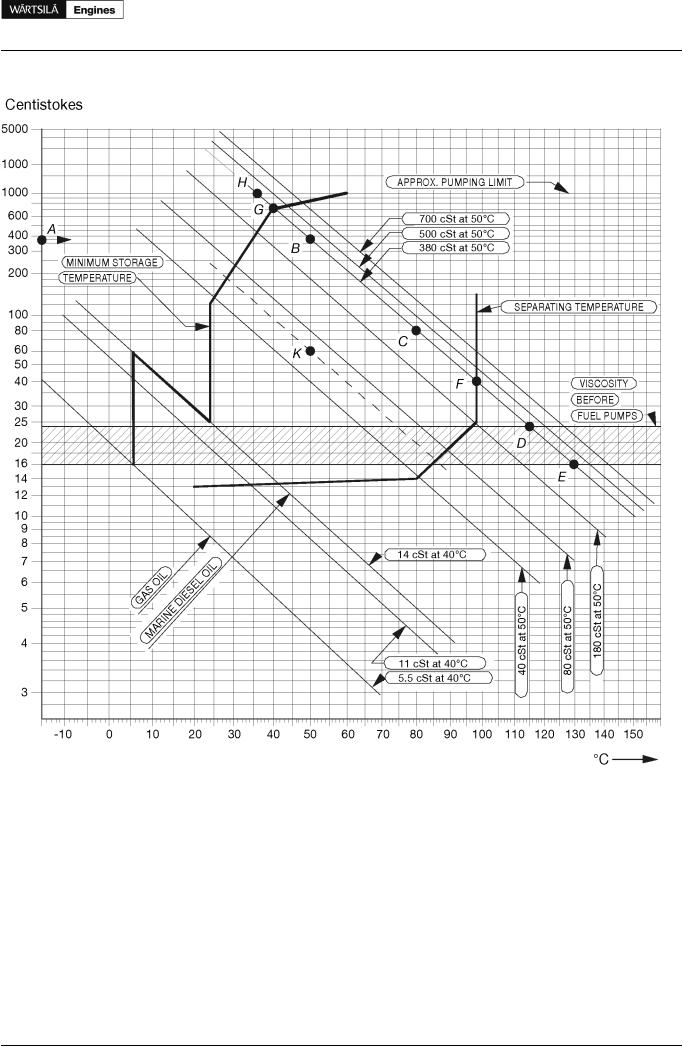
Figure 6.3 Fuel oil viscosity-temperature diagram for determining the pre-heating temperatures of fuel oils (4V92G0071b)
Example 1: A fuel oil with a viscosity of 380 cSt (A) at 50°C (B) or 80 cSt at 80°C (C) must be pre-heated to 115 - 130°C (D-E) before the fuel injection pumps, to 98°C (F) at the separator and to minimum 40°C (G) in the storage tanks. The fuel oil may not be pumpable below 36°C (H).
To obtain temperatures for intermediate viscosities, draw a line from the known viscosity/temperature point in parallel to the nearest viscosity/temperature line in the diagram.
Example 2: Known viscosity 60 cSt at 50°C (K). The following can be read along the dotted line: viscosity at 80°C = 20 cSt, temperature at fuel injection pumps 74 - 87°C, separating temperature 86°C, minimum storage tank temperature 28°C.
6.3.2 Fuel tanks
The fuel oil is first transferred from the bunker tanks to settling tanks for initial separation of sludge and water. After centrifuging the fuel oil is transferred to day tanks, from which fuel is supplied to the engines.
Product Guide Wärtsilä 20 - 3/2009 |
37 |

Product Guide
6. Fuel Oil System
Settling tank, HFO (1T02) and MDF (1T10)
Separate settling tanks for HFO and MDF are recommended.
To ensure sufficient time for settling (water and sediment separation), the capacity of each tank should be sufficient for min. 24 hours operation at maximum fuel consumption.
The tanks should be provided with internal baffles to achieve efficient settling and have a sloped bottom for proper draining.
The temperature in HFO settling tanks should be maintained between 50°C and 70°C, which requires heating coils and insulation of the tank. Usuallly MDF settling tanks do not need heating or insulation, but the tank temperature should be in the range 20...40°C.
Day tank, HFO (1T03) and MDF (1T06)
Two day tanks for HFO are to be provided, each with a capacity sufficient for at least 8 hours operation at maximum fuel consumption.
A separate tank is to be provided for MDF. The capacity of the MDF tank should ensure fuel supply for 8 hours.
Settling tanks may not be used instead of day tanks.
The day tank must be designed so that accumulation of sludge near the suction pipe is prevented and the bottom of the tank should be sloped to ensure efficient draining.
HFO day tanks shall be provided with heating coils and insulation. It is recommended that the viscosity is kept below 140 cSt in the day tanks. Due to risk of wax formation, fuels with a viscosity lower than 50 cSt at 50°C must be kept at a temperature higher than the viscosity would require. Continuous separation is nowadays common practice, which means that the HFO day tank temperature normally remains above 90°C.
The temperature in the MDF day tank should be in the range 20...40°C.
The level of the tank must ensure a positive static pressure on the suction side of the fuel feed pumps. If black-out starting with MDF from a gravity tank is foreseen, then the tank must be located at least 15 m above the engine crankshaft.
Starting tank, MDF (1T09)
The starting tank is needed when the engine is equipped with the engine driven fuel feed pump and when the MDF day tank (1T06) cannot be located high enough, i.e. less than 1.5 meters above the engine crankshaft.
The purpose of the starting tank is to ensure that fuel oil is supplied to the engine during starting. The starting tank shall be located at least 1.5 meters above the engine crankshaft. The volume of the starting tank should be approx. 60 l.
Leak fuel tank, clean fuel (1T04)
Clean leak fuel is drained by gravity from the engine. The fuel should be collected in a separate clean leak fuel tank, from where it can be pumped to the day tank and reused without separation. The pipes from the engine to the clean leak fuel tank should be arranged continuosly sloping. The tank and the pipes must be heated and insulated, unless the installation is designed for operation on MDF only.
The leak fuel piping should be fully closed to prevent dirt from entering the system.
Leak fuel tank, dirty fuel (1T07)
In normal operation no fuel should leak out from the components of the fuel system. In connection with maintenance, or due to unforeseen leaks, fuel or water may spill in the hot box of the engine. The spilled liquids are collected and drained by gravity from the engine through the dirty fuel connection.
Dirty leak fuel shall be led to a sludge tank. The tank and the pipes must be heated and insulated, unless the installation is designed for operation exclusively on MDF.
38 |
Product Guide Wärtsilä 20 - 3/2009 |

Product Guide
6. Fuel Oil System
6.3.3 Fuel treatment
Separation
Heavy fuel (residual, and mixtures of residuals and distillates) must be cleaned in an efficient centrifugal separator before it is transferred to the day tank.
Classification rules require the separator arrangement to be redundant so that required capacity is maintained with any one unit out of operation.
All recommendations from the separator manufacturer must be closely followed.
Centrifugal disc stack separators are recommended also for installations operating on MDF only, to remove water and possible contaminants. The capacity of MDF separators should be sufficient to ensure the fuel supply at maximum fuel consumption. Would a centrifugal separator be considered too expensive for a MDF installation, then it can be accepted to use coalescing type filters instead. A coalescing filter is usually installed on the suction side of the circulation pump in the fuel feed system. The filter must have a low pressure drop to avoid pump cavitation.
Separator mode of operation
The best separation efficiency is achieved when also the stand-by separator is in operation all the time, and the throughput is reduced according to actual consumption.
Separators with monitoring of cleaned fuel (without gravity disc) operating on a continuous basis can handle fuels with densities exceeding 991 kg/m3 at 15°C. In this case the main and stand-by separators should be run in parallel.
When separators with gravity disc are used, then each stand-by separator should be operated in series with another separator, so that the first separator acts as a purifier and the second as clarifier. This arrangement can be used for fuels with a density of max. 991 kg/m3 at 15°C. The separators must be of the same size.
Separation efficiency
The term Certified Flow Rate (CFR) has been introduced to express the performance of separators according to a common standard. CFR is defined as the flow rate in l/h, 30 minutes after sludge discharge, at which the separation efficiency of the separator is 85%, when using defined test oils and test particles. CFR is defined for equivalent fuel oil viscosities of 380 cSt and 700 cSt at 50°C. More information can be found in the CEN (European Committee for Standardisation) document CWA 15375:2005 (E).
The separation efficiency is measure of the separator's capability to remove specified test particles. The separation efficiency is defined as follows:
where: |
|
n = |
separation efficiency [%] |
Cout = |
number of test particles in cleaned test oil |
Cin = |
number of test particles in test oil before separator |
Separator unit (1N02/1N05)
Separators are usually supplied as pre-assembled units designed by the separator manufacturer. Typically separator modules are equipped with:
•Suction strainer (1F02)
•Feed pump (1P02)
•Pre-heater (1E01)
•Sludge tank (1T05)
•Separator (1S01/1S02)
Product Guide Wärtsilä 20 - 3/2009 |
39 |

Product Guide
6.Fuel Oil System
•Sludge pump
•Control cabinets including motor starters and monitoring
Figure 6.4 Fuel transfer and separating system (3V76F6626d)
Separator feed pumps (1P02)
Feed pumps should be dimensioned for the actual fuel quality and recommended throughput of the separator. The pump should be protected by a suction strainer (mesh size about 0.5 mm)
An approved system for control of the fuel feed rate to the separator is required.
Design data: |
HFO |
MDF |
Design pressure |
0.5 MPa (5 bar) |
0.5 MPa (5 bar) |
Design temperature |
100°C |
50°C |
Viscosity for dimensioning electric motor |
1000 cSt |
100 cSt |
Separator pre-heater (1E01)
The pre-heater is dimensioned according to the feed pump capacity and a given settling tank temperature.
The surface temperature in the heater must not be too high in order to avoid cracking of the fuel. The temperature control must be able to maintain the fuel temperature within ± 2°C.
40 |
Product Guide Wärtsilä 20 - 3/2009 |
Product Guide
6. Fuel Oil System
Recommended fuel temperature after the heater depends on the viscosity, but it is typically 98°C for HFO and 20...40°C for MDF. The optimum operating temperature is defined by the sperarator manufacturer.
The required minimum capacity of the heater is:
where: |
|
P = |
heater capacity [kW] |
Q = |
capacity of the separator feed pump [l/h] |
T = |
temperature rise in heater [°C] |
For heavy fuels T = 48°C can be used, i.e. a settling tank temperature of 50°C. Fuels having a viscosity higher than 5 cSt at 50°C require pre-heating before the separator.
The heaters to be provided with safety valves and drain pipes to a leakage tank (so that the possible leakage can be detected).
Separator (1S01/1S02)
Based on a separation time of 23 or 23.5 h/day, the service throughput Q [l/h] of the separator can be estimated with the formula:
where:
P = max. continuous rating of the diesel engine(s) [kW]
b = specific fuel consumption + 15% safety margin [g/kWh]
ρ = density of the fuel [kg/m3]
t = daily separating time for self cleaning separator [h] (usually = 23 h or 23.5 h)
The flow rates recommended for the separator and the grade of fuel must not be exceeded. The lower the flow rate the better the separation efficiency.
Sample valves must be placed before and after the separator.
MDF separator in HFO installations (1S02)
A separator for MDF is recommended also for installations operating primarily on HFO. The MDF separator can be a smaller size dedicated MDF separator, or a stand-by HFO separator used for MDF.
Sludge tank (1T05)
The sludge tank should be located directly beneath the separators, or as close as possible below the separators, unless it is integrated in the separator unit. The sludge pipe must be continuously falling.
Product Guide Wärtsilä 20 - 3/2009 |
41 |

Product Guide
6. Fuel Oil System
6.3.4 Fuel feed system - MDF installations
Figure 6.5 Fuel feed system, main engine (DAAE003608b)
System components |
Pipe connections |
||
1F07 |
Suction strainer (MDF) |
101 |
Fuel inlet |
1P08 |
Stand-by pump (MDF) |
102 |
Fuel outlet |
1T04 |
Leak fuel tank, clean fuel |
103 |
Leak fuel drain, clean fuel |
1T06 |
Day tank (MDF) |
1041 |
Leak fuel drain, dirty fuel free end |
1T07 |
Leak fuel tank, dirty fuel |
1043 |
Leak fuel drain, dirty fuel FW-end |
|
|
105 |
Fuel stand-by connection |
If the engines are to be operated on MDF only, heating of the fuel is normally not necessary. In such case it is sufficient to install the equipment listed below. Some of the equipment listed below is also to be installed in the MDF part of a HFO fuel oil system.
42 |
Product Guide Wärtsilä 20 - 3/2009 |

Product Guide
6. Fuel Oil System
Circulation pump, MDF (1P03)
The circulation pump maintains the pressure at the injection pumps and circulates the fuel in the system. It is recommended to use a screw pump as circulation pump. A suction strainer with a fineness of 0.5 mm should be installed before each pump. There must be a positive static pressure of about 30 kPa on the suction side of the pump.
Design data: |
|
Capacity |
5 x the total consumption of the connected engines |
Design pressure |
1.6 MPa (16 bar) |
Max. total pressure (safety valve) |
1.0 MPa (10 bar) |
Design temperature |
50°C |
Viscosity for dimensioning of electric motor |
90 cSt |
Stand-by pump, MDF (1P08)
The stand-by pump is required in case of a single main engine equipped with an engine driven pump. It is recommended to use a screw pump as stand-by pump. The pump should be placed so that a positive static pressure of about 30 kPa is obtained on the suction side of the pump.
Design data: |
|
Capacity |
5 x the total consumption of the connected engine |
Design pressure |
1.6 MPa (16 bar) |
Max. total pressure (safety valve) |
1.2 MPa (12 bar) |
Design temperature |
50°C |
Viscosity for dimensioning of electric motor |
90 cSt |
Flow meter, MDF (1I03)
If the return fuel from the engine is conducted to a return fuel tank instead of the day tank, one consumption meter is sufficient for monitoring of the fuel consumption, provided that the meter is installed in the feed line from the day tank (before the return fuel tank). A fuel oil cooler is usually required with a return fuel tank.
The total resistance of the flow meter and the suction strainer must be small enough to ensure a positive static pressure of about 30 kPa on the suction side of the circulation pump.
There should be a by-pass line around the consumption meter, which opens automatically in case of excessive pressure drop.
Fine filter, MDF (1F05)
The fuel oil fine filter is a full flow duplex type filter with steel net. This filter must be installed as near the engine as possible.
The diameter of the pipe between the fine filter and the engine should be the same as the diameter before the filters.
Design data: |
|
Fuel viscosity |
according to fuel specifications |
Design temperature |
50°C |
Design flow |
Equal to feed/circulation pump capacity |
Design pressure |
1.6 MPa (16 bar) |
Fineness |
37 μm (absolute mesh size) |
Maximum permitted pressure drops at 14 cSt: |
|
- clean filter |
20 kPa (0.2 bar) |
- alarm |
80 kPa (0.8 bar) |
Product Guide Wärtsilä 20 - 3/2009 |
43 |

Product Guide
6. Fuel Oil System
Pressure control valve, MDF (1V02)
The pressure control valve is installed when the installation includes a feeder/booster unit for HFO and there is a return line from the engine to the MDF day tank. The purpose of the valve is to increase the pressure in the return line so that the required pressure at the engine is achieved.
Design data: |
|
Capacity |
Equal to circulation pump |
Design temperature |
50°C |
Design pressure |
1.6 MPa (16 bar) |
Set point |
0.4...0.7 MPa (4...7 bar) |
MDF cooler (1E04)
The fuel viscosity may not drop below the minimum value stated in Technical data. When operating on MDF, the practical consequence is that the fuel oil inlet temperature must be kept below 45...50°C. Very light fuel grades may require even lower temperature.
Sustained operation on MDF usually requires a fuel oil cooler. The cooler is to be installed in the return line after the engine(s). LT-water is normally used as cooling medium.
Design data: |
|
Heat to be dissipated |
1 kW/cyl |
Max. pressure drop, fuel oil |
80 kPa (0.8 bar) |
Max. pressure drop, water |
60 kPa (0.6 bar) |
Margin (heat rate, fouling) |
min. 15% |
Design temperature MDF/HFO installation |
50/150°C |
Return fuel tank (1T13)
The return fuel tank shall be equipped with a vent valve needed for the vent pipe to the MDF day tank. The volume of the return fuel tank should be at least 100 l.
Black out start
Diesel generators serving as the main source of electrical power must be able to resume their operation in a black out situation by means of stored energy. Depending on system design and classification regulations, it may in some cases be permissible to use the emergency generator. Sufficient fuel pressure to enable black out start can be achieved by means of:
•A gravity tank located min. 15 m above the crankshaft
•A pneumatically driven fuel feed pump (1P11)
•An electrically driven fuel feed pump (1P11) powered by an emergency power source
44 |
Product Guide Wärtsilä 20 - 3/2009 |
Product Guide
6. Fuel Oil System
6.3.5 Fuel feed system - HFO installations
Figure 6.6 Example of fuel oil system (HFO), multiple engine installation (3V76F6656e)
System components |
|
|
|
1E02 |
Heater (booster unit) |
1P06 |
Circulation pump (booster unit) |
1E03 |
Cooler (booster unit) |
1T03 |
Day tank (HFO) |
1E04 |
Cooler (MDF return line) |
1T04 |
Leak fuel tank (clean fuel) |
1F03 |
Safety filter (HFO) |
1T06 |
Day tank (MDF) |
1F05 |
Safety filter (MDF) |
1T07 |
Leak fuel tank (dirty fuel) |
1F06 |
Suction filter (booster unit) |
1T08 |
De-aeration tank (booster unit) |
1F07 |
Suction strainer (MDF) |
1V01 |
Change over valve |
1F08 |
Automatic filter (booster unit) |
1V02 |
Pressure control valve (MDF) |
1I01 |
Flowmeter (booster unit) |
1V03 |
Pressure control valve (booster unit) |
1I02 |
Viscosity meter (booster unit) |
1V04 |
Pressure control valve (HFO) |
1N01 |
Feeder/Booster unit |
1V05 |
Overflow valve (HFO/MDF) |
1P03 |
Circulation pump (MDF) |
1V07 |
Venting valve (booster unit) |
1P04 |
Fuel feed pump (booster unit) |
1V08 |
Change over valve |
Pipe connections |
|
|
|
101 |
Fuel inlet |
1041 |
Leak fuel drain, dirty fuel free end |
102 |
Fuel outlet |
1043 |
Leak fuel drain, dirty fuel driving-end |
103 Leak fuel drain, clean fuel
Product Guide Wärtsilä 20 - 3/2009 |
45 |

Product Guide
6. Fuel Oil System
HFO pipes shall be properly insulated. If the viscosity of the fuel is 180 cSt/50°C or higher, the pipes must be equipped with trace heating. It shall be possible to shut off the heating of the pipes when operating on MDF (trace heating to be grouped logically).
Starting and stopping
The engine can be started and stopped on HFO provided that the engine and the fuel system are pre-heated to operating temperature. The fuel must be continuously circulated also through a stopped engine in order to maintain the operating temperature. Changeover to MDF for start and stop is not required.
Prior to overhaul or shutdown of the external system the engine fuel system shall be flushed and filled with MDF.
Changeover from HFO to MDF
The control sequence and the equipment for changing fuel during operation must ensure a smooth change in fuel temperature and viscosity. When MDF is fed through the HFO feeder/booster unit, the volume in the system is sufficient to ensure a reasonably smooth transfer.
When there are separate circulating pumps for MDF, then the fuel change should be performed with the HFO feeder/booster unit before switching over to the MDF circulating pumps. As mentioned earlier, sustained operation on MDF usually requires a fuel oil cooler. The viscosity at the engine shall not drop below the minimum limit stated in chapter Technical data.
Number of engines in the same system
When the fuel feed unit serves Wärtsilä 20 engines only, maximum three engines should be connected to the same fuel feed circuit, unless individual circulating pumps before each engine are installed.
Main engines and auxiliary engines should preferably have separate fuel feed units. Individual circulating pumps or other special arrangements are often required to have main engines and auxiliary engines in the same fuel feed circuit. Regardless of special arrangements it is not recommended to supply more than maximum two main engines and two auxiliary engines, or one main engine and three auxiliary engines from the same fuel feed unit.
In addition the following guidelines apply:
•Twin screw vessels with two engines should have a separate fuel feed circuit for each propeller shaft.
•Twin screw vessels with four engines should have the engines on the same shaft connected to different fuel feed circuits. One engine from each shaft can be connected to the same circuit.
Feeder/booster unit (1N01)
A completely assembled feeder/booster unit can be supplied. This unit comprises the following equipment:
•Two suction strainers
•Two fuel feed pumps of screw type, equipped with built-on safety valves and electric motors
•One pressure control/overflow valve
•One pressurized de-aeration tank, equipped with a level switch operated vent valve
•Two circulating pumps, same type as the fuel feed pumps
•Two heaters, steam, electric or thermal oil (one heater in operation, the other as spare)
•One automatic back-flushing filter with by-pass filter
•One viscosimeter for control of the heaters
•One control valve for steam or thermal oil heaters, a control cabinet for electric heaters
•One thermostatic valve for emergency control of the heaters
•One control cabinet including starters for pumps
•One alarm panel
The above equipment is built on a steel frame, which can be welded or bolted to its foundation in the ship. The unit has all internal wiring and piping fully assembled. All HFO pipes are insulated and provided with trace heating.
46 |
Product Guide Wärtsilä 20 - 3/2009 |
Product Guide
6. Fuel Oil System
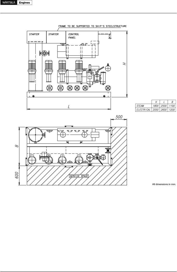
Figure 6.7 Feeder/booster unit, example (DAAE006659)
Fuel feed pump, booster unit (1P04)
The feed pump maintains the pressure in the fuel feed system. It is recommended to use a screw pump as feed pump. The capacity of the feed pump must be sufficient to prevent pressure drop during flushing of the automatic filter.
A suction strainer with a fineness of 0.5 mm should be installed before each pump. There must be a positive static pressure of about 30 kPa on the suction side of the pump.
Design data: |
|
|
|
Capacity |
Total consumption of the connected engines added with the |
||
flush quantity of the automatic filter (1F08) |
|||
|
|||
Design pressure |
1.6 |
MPa (16 bar) |
|
Max. total pressure (safety valve) |
0.7 |
MPa (7 bar) |
|
Design temperature |
100°C |
||
Viscosity for dimensioning of electric motor |
1000 cSt |
||
Product Guide Wärtsilä 20 - 3/2009 |
47 |

Product Guide
6. Fuel Oil System
Pressure control valve, booster unit (1V03)
The pressure control valve in the feeder/booster unit maintains the pressure in the de-aeration tank by directing the surplus flow to the suction side of the feed pump.
Design data: |
|
Capacity |
Equal to feed pump |
Design pressure |
1.6 MPa (16 bar) |
Design temperature |
100°C |
Set-point |
0.3...0.5 MPa (3...5 bar) |
Automatic filter, booster unit (1F08)
It is recommended to select an automatic filter with a manually cleaned filter in the bypass line. The automatic filter must be installed before the heater, between the feed pump and the de-aeration tank, and it should be equipped with a heating jacket. Overheating (temperature exceeding 100°C) is however to be prevented, and it must be possible to switch off the heating for operation on MDF.
Design data:
Fuel viscosity
Design temperature
Preheating
Design flow
Design pressure
Fineness:
-automatic filter
-by-pass filter
Maximum permitted pressure drops at 14 cSt:
-clean filter
-alarm
According to fuel specification 100°C
If fuel viscosity is higher than 25 cSt/100°C Equal to feed pump capacity
1.6 MPa (16 bar)
35 μm (absolute mesh size)
35 μm (absolute mesh size)
20 kPa (0.2 bar)
80 kPa (0.8 bar)
Flow meter, booster unit (1I01)
If a fuel consumption meter is required, it should be fitted between the feed pumps and the de-aeration tank. When it is desired to monitor the fuel consumption of individual engines in a multiple engine installation, two flow meters per engine are to be installed: one in the feed line and one in the return line of each engine.
There should be a by-pass line around the consumption meter, which opens automatically in case of excessive pressure drop.
If the consumption meter is provided with a prefilter, an alarm for high pressure difference across the filter is recommended.
De-aeration tank, booster unit (1T08)
It shall be equipped with a low level alarm switch and a vent valve. The vent pipe should, if possible, be led downwards, e.g. to the overflow tank. The tank must be insulated and equipped with a heating coil. The volume of the tank should be at least 100 l.
Circulation pump, booster unit (1P06)
The purpose of this pump is to circulate the fuel in the system and to maintain the required pressure at the injection pumps, which is stated in the chapter Technical data. By circulating the fuel in the system it also maintains correct viscosity, and keeps the piping and the injection pumps at operating temperature.
Design data: |
|
Capacity |
5 x the total consumption of the connected engines |
Design pressure |
1.6 MPa (16 bar) |
Max. total pressure (safety valve) |
1.0 MPa (10 bar) |
48 Product Guide Wärtsilä 20 - 3/2009
Product Guide
6. Fuel Oil System
Design data: |
|
Design temperature |
150°C |
Viscosity for dimensioning of electric motor |
500 cSt |
Heater, booster unit (1E02)
The heater must be able to maintain a fuel viscosity of 14 cSt at maximum fuel consumption, with fuel of the specified grade and a given day tank temperature (required viscosity at injection pumps stated in Technical data). When operating on high viscosity fuels, the fuel temperature at the engine inlet may not exceed 135°C however.
The power of the heater is to be controlled by a viscosimeter. The set-point of the viscosimeter shall be somewhat lower than the required viscosity at the injection pumps to compensate for heat losses in the pipes. A thermostat should be fitted as a backup to the viscosity control.
To avoid cracking of the fuel the surface temperature in the heater must not be too high. The heat transfer rate in relation to the surface area must not exceed 1.5 W/cm2.
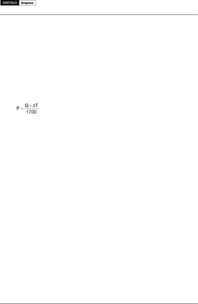
The required heater capacity can be estimated with the following formula:
where:
P = heater capacity (kW)
Q = total fuel consumption at full output + 15% margin [l/h]
T = temperature rise in heater [°C]
Viscosimeter, booster unit (1I02)
The heater is to be controlled by a viscosimeter. The viscosimeter should be of a design that can withstand the pressure peaks caused by the injection pumps of the diesel engine.
Design data: |
|
Operating range |
0...50 cSt |
Design temperature |
180°C |
Design pressure |
4 MPa (40 bar) |
Safety filter (1F03)
The safety filter is a full flow duplex type filter with steel net. This safety filter must be installed as close as possible to the engines. The safety filter should be equipped with a heating jacket. In multiple engine installations it is possible to have a one common safety filter for all engines.
The diameter of the pipe between the safety filter and the engine should be the same as between the feeder/booster unit and the safety filter.
Design data: |
|
Fuel viscosity |
according to fuel specification |
Design temperature |
150°C |
Design flow |
Equal to circulation pump capacity |
Design pressure |
1.6 MPa (16 bar) |
Fineness |
37 μm (absolute mesh size) |
Maximum permitted pressure drops at 14 cSt: |
|
- clean filter |
20 kPa (0.2 bar) |
- alarm |
80 kPa (0.8 bar) |
Product Guide Wärtsilä 20 - 3/2009 |
49 |

Product Guide
6. Fuel Oil System
Overflow valve, HFO (1V05)
When several engines are connected to the same feeder/booster unit an overflow valve is needed between the feed line and the return line. The overflow valve limits the maximum pressure in the feed line, when the fuel lines to a parallel engine are closed for maintenance purposes.
The overflow valve should be dimensioned to secure a stable pressure over the whole operating range.
Design data: |
|
Capacity |
Equal to circulation pump (1P06) |
Design pressure |
1.6 MPa (16 bar) |
Design temperature |
150°C |
Set-point ( p) |
0.1...0.2 MPa (1...2 bar) |
Pressure control valve (1V04)
The pressure control valve increases the pressure in the return line so that the required pressure at the engine is achieved. This valve is needed in installations where the engine is equipped with an adjustable throttle valve in the return fuel line of the engine.
The adjustment of the adjustable throttle valve on the engine should be carried out after the pressure control valve (1V04) has been adjusted. The adjustment must be tested in different loading situations including the cases with one or more of the engines being in stand-by mode. If the main engine is connected to the same feeder/booster unit the circulation/temperatures must also be checked with and without the main engine being in operation.
6.3.6 Flushing
Theexternalpipingsystemmustbethoroughlyflushedbeforetheenginesareconnectedandfueliscirculated through the engines. The piping system must have provisions for installation of a temporary flushing filter.
The fuel pipes at the engine (connections 101 and 102) are disconnected and the supply and return lines are connected with a temporary pipe or hose on the installation side. All filter inserts are removed, except in the flushing filter of course. The automatic filter and the viscosimeter should be bypassed to prevent damage. The fineness of the flushing filter should be 35 μm or finer.
50 |
Product Guide Wärtsilä 20 - 3/2009 |