


Product Guide
16. Vibration and Noise
16. Vibration and Noise
Wärtsilä 20 generating sets comply with vibration levels according to ISO 8528-9. Main engines comply with vibration levels according to ISO 10816-6 Class 5.
16.1 External forces and couples
Some cylinder configurations produce external forces and couples. These are listed in the tables below.
The ship designer should avoid natural frequencies of decks, bulkheads and superstructures close to the excitation frequencies. The double bottom should be stiff enough to avoid resonances especially with the rolling frequencies.
Figure 16.1 Coordinate system
Table 16.1 External forces |
|
|
|
Engine |
Speed [rpm] |
Frequency [Hz] |
Fz [kN] |
W 4L20 |
900 |
30 |
56 |
|
|
60 |
1 |
|
1000 |
33.3 |
69 |
|
|
67 |
1 |
W 8L20 |
900 |
60 |
2 |
|
1000 |
66.7 |
3 |
FZ = 0, FY = 0 and FX = 0 for 6 and 9 cylinder engines
Table 16.2 External couples
Engine |
Speed [rpm] |
Frequency [Hz] |
MY [kNm] |
Frequency [Hz] |
MZ [kNm] |
W 9L20 |
900 |
15 |
7 |
15 |
7 |
|
|
30 |
4.8 |
|
|
|
|
60 |
0.4 |
|
|
|
1000 |
16.7 |
8.6 |
16.7 |
8.6 |
|
|
33.3 |
5.9 |
|
|
|
|
66.7 |
0.5 |
|
|
MZ = 0, MY = 0 for 4, 6 and 8 cylinder engines
120 |
Product Guide Wärtsilä 20 - 3/2009 |

Product Guide
16. Vibration and Noise
16.1.1 Torque variations
Table 16.3 Rolling moments at 100% load |
|
|
|
|
|
||
Engine |
Speed |
Frequency [Hz] |
MX [kNm] |
Frequency [Hz] |
MX [kNm] |
Frequency [Hz] |
MX [kNm] |
|
[rpm] |
|
|
|
|
|
|
W 4L20 |
900 |
30 |
9.9 |
60 |
9.8 |
90 |
3.5 |
|
1000 |
33.3 |
6.6 |
66.7 |
9.6 |
100 |
3.5 |
W 6L20 |
900 |
45 |
15.4 |
90 |
5.2 |
135 |
0.4 |
|
1000 |
50 |
13.4 |
100 |
5.2 |
200 |
0.4 |
W 8L20 |
900 |
60 |
19.6 |
120 |
1.5 |
180 |
0.5 |
|
1000 |
66.7 |
19.3 |
133 |
1.5 |
200 |
0.5 |
W 9L20 |
900 |
67.5 |
17.8 |
135 |
0.6 |
203 |
0.4 |
|
1000 |
75 |
17.7 |
150 |
0.7 |
225 |
0.4 |
Table 16.4 Rolling moments at 0 % load |
|
|
|
|
|
||
Engine |
Speed |
Frequency [Hz] |
MX [kNm] |
Frequency [Hz] |
MX [kNm] |
Frequency [Hz] |
MX [kNm] |
|
[rpm] |
|
|
|
|
|
|
W 4L20 |
900 |
30 |
10 |
60 |
1.4 |
90 |
0.9 |
|
1000 |
33.3 |
13 |
66.7 |
1.3 |
100 |
0.9 |
W 6L20 |
900 |
45 |
4.7 |
90 |
1.3 |
135 |
0.4 |
|
1000 |
50 |
6.8 |
100 |
1.3 |
150 |
0.4 |
W 8L20 |
900 |
60 |
2.8 |
120 |
0.7 |
- |
- |
|
1000 |
66.7 |
2.6 |
133 |
0.7 |
- |
- |
W 9L20 |
900 |
67.5 |
3.6 |
135 |
0.5 |
- |
- |
|
1000 |
75 |
3.6 |
150 |
0.5 |
- |
- |
16.2 Mass moments of inertia
The mass-moments of inertia of the propulsion engines (including flywheel, coupling outer part and damper) are typically as follows:
Engine |
J [kgm²] |
W 4L20 |
90...120 |
W 6L20 |
90...150 |
W 8L20 |
110...160 |
W 9L20 |
100...170 |
Product Guide Wärtsilä 20 - 3/2009 |
121 |
Product Guide
16. Vibration and Noise
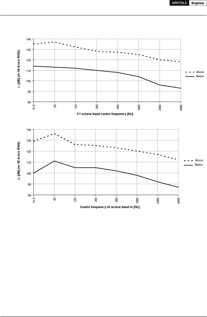
16.3 Structure borne noise
Figure 16.2 Main engines, typical structure borne noise levels above and below resilient mounts (DAAB814306)
Figure 16.3 Generating sets, typical structure borne noise levels above and below resilient mounts (DBAB120103)
122 |
Product Guide Wärtsilä 20 - 3/2009 |
Product Guide
16. Vibration and Noise
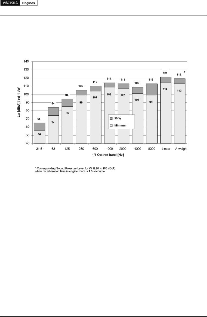
16.4 Air borne noise
The airborne noise of the engine is measured as a sound power level according to ISO 9614-2. The results are presented with A-weighing in octave bands, reference level 1 pW. Two values are given; a minimum value and a 90% value. The minimum value is the smallest sound power level found in the measurements. The 90% level is such that 90% of all measured values are below this figure.
Figure 16.4 Sound power levels
Product Guide Wärtsilä 20 - 3/2009 |
123 |