

Product Guide
9. Cooling Water System
9.Cooling Water System
9.1Water quality
The fresh water in the cooling water system of the engine must fulfil the following requirements:
pH ............................... |
min. 6.5 |
Hardness .................... |
max. 10 °dH |
Chlorides .................... |
max. 80 mg/l |
Sulphates .................... |
max. 150 mg/l |
Good quality tap water can be used, but shore water is not always suitable. It is recommended to use water produced by an onboard evaporator. Fresh water produced by reverse osmosis plants often has higher chloride content than permitted. Rain water is unsuitable as cooling water due to the high content of oxygen and carbon dioxide.
Only treated fresh water containing approved corrosion inhibitors may be circulated through the engines. It is important that water of acceptable quality and approved corrosion inhibitors are used directly when the system is filled after completed installation.
9.1.1 Corrosion inhibitors
The use of an approved cooling water additive is mandatory. An updated list of approved products is supplied for every installation and it can also be found in the Instruction manual of the engine, together with dosage and further instructions.
9.1.2 Glycol
Use of glycol in the cooling water is not recommended unless it is absolutely necessary. Starting from 20% glycol the engine is to be de-rated 0.23 % per 1% glycol in the water. Max. 50% glycol is permitted.
Corrosion inhibitors shall be used regardless of glycol in the cooling water.
Product Guide Wärtsilä 20 - 3/2009 |
65 |
Product Guide
9. Cooling Water System
9.2Internal cooling water system
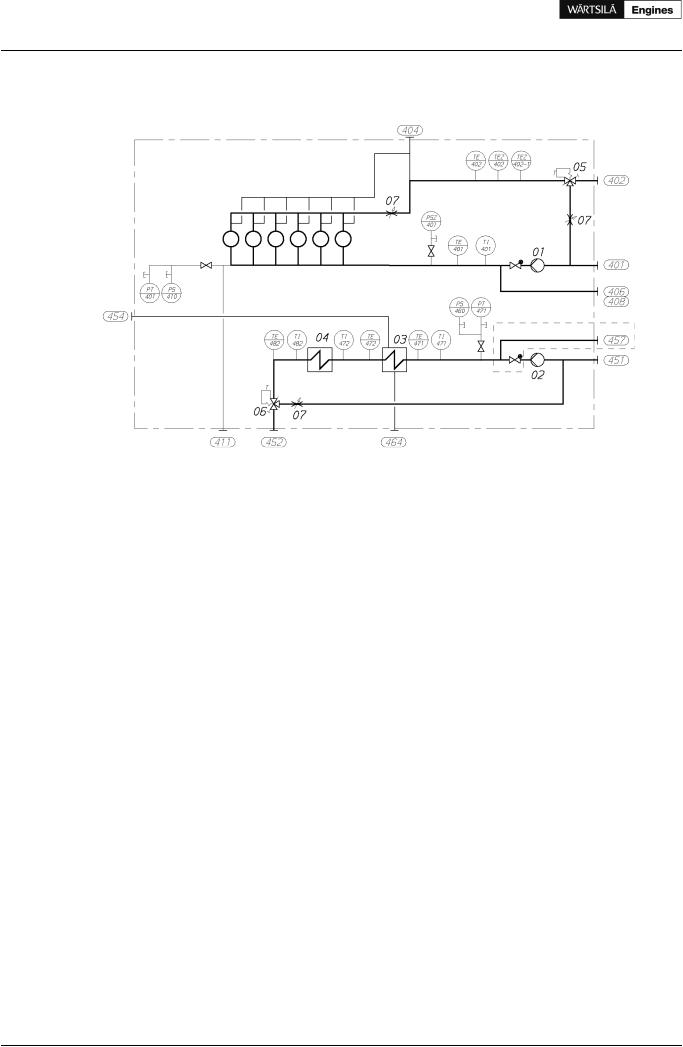
Figure 9.1 Internal cooling water system (DAAE060388a)
System components: |
|
|
|
01 |
HT-cooling water pump |
05 |
HT-thermostatic valve |
02 |
LT-cooling water pump |
06 |
LT-thermostatic valve |
03 |
Charge air cooler |
07 |
Adjustable orifice |
04 |
Lubricating oil cooler |
|
|
Sensors and Indicators: |
|
|
|
|
PT401 |
HT water pressure, jacket inlet |
PT471 |
LT water pressure, CAC inlet |
|
PSZ401 |
HT water pressure switch. jacket inlet (if GL and ME) PS460 |
LT water pressure switch, stand-by pump |
||
PS410 |
HT water pressure switch, stand-by pump |
TE471 |
LT water temperature, CAC inlet |
|
TE401 |
HT water temperature, jacket inlet |
TI471 |
LT water temperature, CAC inlet (option) |
|
TI401 |
HT water temperature, jacket inlet (option) |
TE472 |
LT water temperature, CAC outlet (if FAKS/CBM) |
|
TE402 |
HT water temperature, engine outlet |
TI472 |
LT water temperature, CAC outlet (option) |
|
TEZ402 HT water temperature, engine outlet |
TE482 |
LT water temperature, LOC outlet |
||
TEZ401-2 HT water temperature, engine outlet |
TI482 |
LT water temperature, LOC outlet (option) |
||
|
(if ABS/LRS/RS/CCS) |
|
|
|
Pipe connections |
Size |
Pressure class |
Standard |
|
401 |
HT-water inlet |
DN65 |
PN16 |
ISO 7005-1 |
402 |
HT-water outlet |
DN65 |
PN16 |
ISO 7005-1 |
404 |
HT-water air vent |
OD12 |
PN250 |
DIN 2353 |
406 |
Water from preheater to HT-circuit |
DN65 |
PN16 |
ISO 7005-1 |
408 |
HT-water from stand-by pump |
DN65 |
PN16 |
ISO 7005-1 |
411 |
HT-water drain |
M10 x 1 |
- |
Plug |
451 |
LT-water inlet |
DN80 |
PN16 |
ISO 7005-1 |
452 |
LT-water outlet |
DN80 |
PN16 |
ISO 7005-1 |
454 |
LT-water air vent from air cooler |
OD12 |
PN250 |
DIN 2353 |
457 |
LT-water from stand-by pump |
DN80 |
PN16 |
ISO 7005-1 |
464 |
LT-water drain |
M18 x 1.5 |
- |
Plug |
66 Product Guide Wärtsilä 20 - 3/2009
Product Guide
9. Cooling Water System
The fresh water cooling system is divided into a high temperature (HT) and a low temperature (LT) circuit. The HT water circulates through cylinder jackets and cylinder heads.
The LT water circulates through the charge air cooler and the lubricating oil cooler, which is built on the engine.
Temperature control valves regulate the temperature of the water out from the engine, by circulating some water back to the cooling water pump inlet. The HT temperature control valve is always mounted on the engine, while the LT temperature control valve can be either on the engine or separate. In installations where the engines operate on MDF only it is possible to install the LT temperature control valve in the external system and thus control the LT water temperature before the engine.
9.2.1 Engine driven circulating pumps
The LT and HT cooling water pumps are engine driven. The engine driven pumps are located at the free end of the engine.
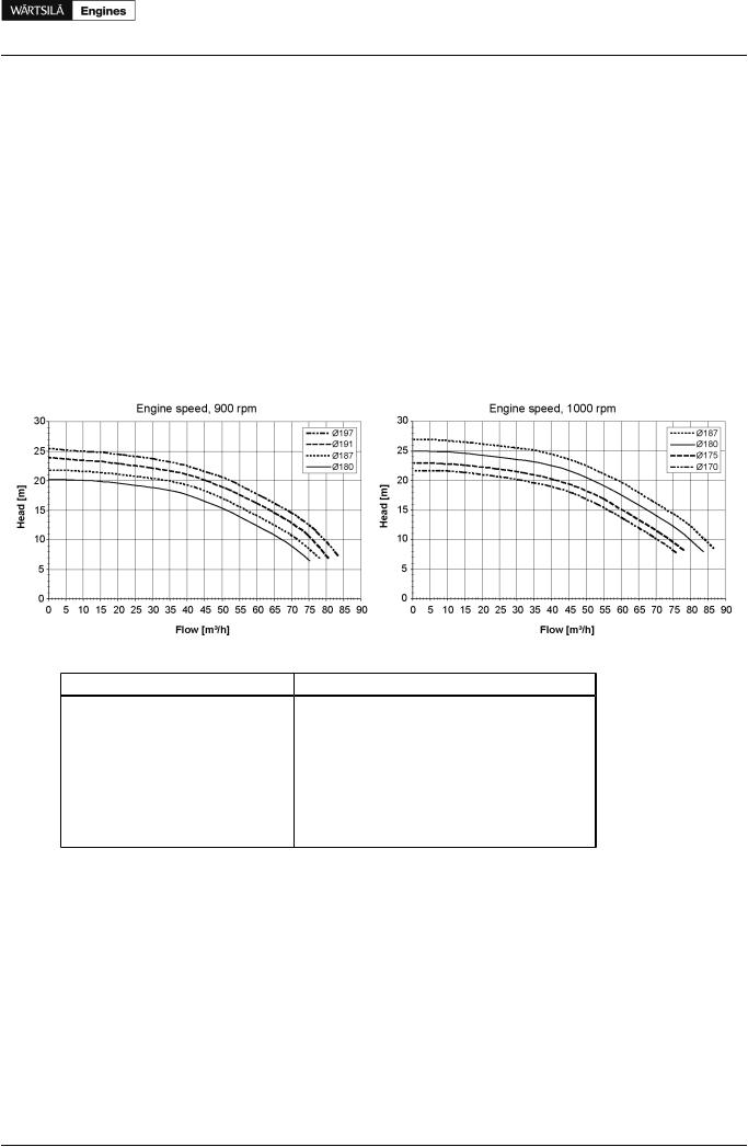
Pump curves for engine driven pumps are shown in the diagrams. The nominal pressure and capacity can be found in the chapter Technical data.
Figure 9.2 Pump curves
Table 9.1 Impeller diameters of engine driven HT & LT pumps |
|
||
Engine |
Engine speed [rpm] |
HT impeller [Ø mm] |
LT impeller [Ø mm] |
W 4L20 |
900 |
180 |
187 |
|
1000 |
170 |
170 |
W 6L20 |
900 |
187 |
187 |
|
1000 |
175 |
175 |
W 8L20 |
900 |
191 |
197 |
|
1000 |
180 |
187 |
W 9L20 |
900 |
191 |
197 |
|
1000 |
180 |
187 |
Product Guide Wärtsilä 20 - 3/2009 |
67 |
Product Guide
9. Cooling Water System
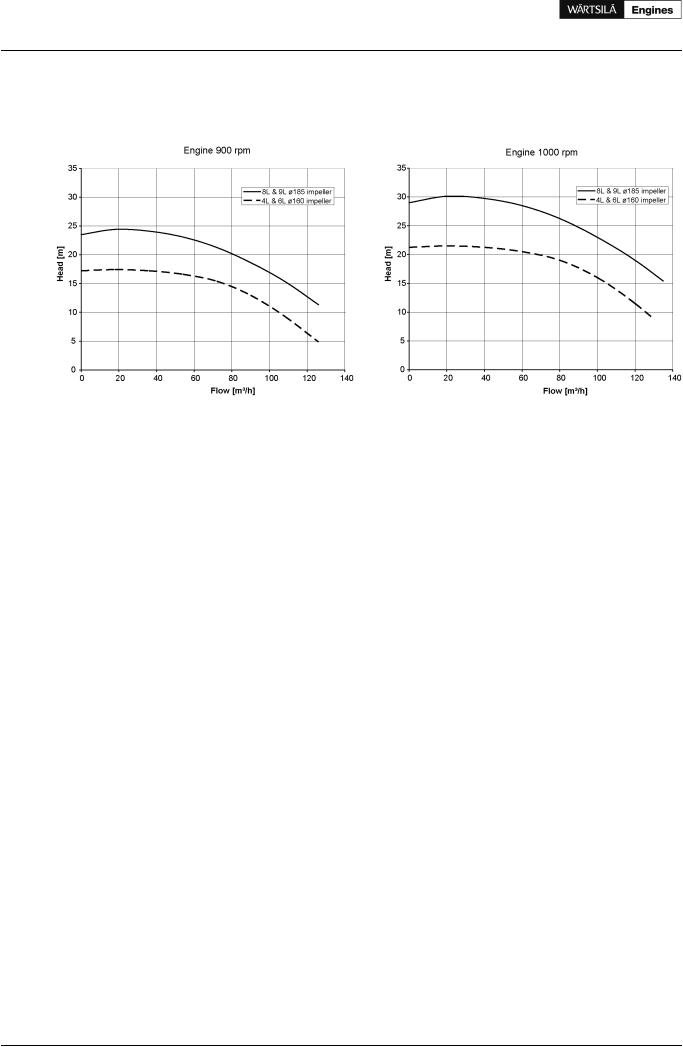
9.2.2 Engine driven sea water pump
An engine driven sea water pump is available for main engines:
Figure 9.3 Engine driven sea water pump curves
9.2.3 Temperature control valve LT-circuit
The direct acting thermostatic valve controls the outlet water temperature.
set point |
49°C (43...54°C) |
9.2.4 Temperature control valve HT-circuit
The direct acting thermostatic valve controls the outlet water temperature.
set point |
91°C (87...98°C) |
68 |
Product Guide Wärtsilä 20 - 3/2009 |