- •Introduction
- •Table of Contents
- •1. Main Data and Outputs
- •1.1 Maximum continuous output
- •1.2 Reference conditions
- •1.3 Operation in inclined position
- •1.4 Dimensions and weights
- •2. Operating ranges
- •2.1 Engine operating range
- •2.2 Loading capacity
- •2.3 Low air temperature
- •2.4 Operation at low load and idling
- •3. Technical Data
- •3.1 Wärtsilä 4L20
- •3.2 Wärtsilä 6L20
- •3.3 Wärtsilä 8L20
- •3.4 Wärtsilä 9L20
- •4. Description of the Engine
- •4.1 Definitions
- •4.2 Main components and systems
- •4.3 Cross sections of the engine
- •4.4 Overhaul intervals and expected lifetimes
- •5. Piping Design, Treatment and Installation
- •5.1 Pipe dimensions
- •5.2 Trace heating
- •5.3 Operating and design pressure
- •5.4 Pipe class
- •5.5 Insulation
- •5.6 Local gauges
- •5.7 Cleaning procedures
- •5.8 Flexible pipe connections
- •5.9 Clamping of pipes
- •6. Fuel Oil System
- •6.1 Acceptable fuel characteristics
- •6.2 Internal fuel oil system
- •6.3 External fuel oil system
- •7. Lubricating Oil System
- •7.1 Lubricating oil requirements
- •7.2 Internal lubricating oil system
- •7.3 External lubricating oil system
- •7.4 Crankcase ventilation system
- •7.5 Flushing instructions
- •8. Compressed Air System
- •8.1 Internal compressed air system
- •8.2 External compressed air system
- •9. Cooling Water System
- •9.1 Water quality
- •9.2 Internal cooling water system
- •9.3 External cooling water system
- •10. Combustion Air System
- •10.1 Engine room ventilation
- •10.2 Combustion air system design
- •11. Exhaust Gas System
- •11.1 Internal exhaust gas system
- •11.2 Exhaust gas outlet
- •11.3 External exhaust gas system
- •12. Turbocharger Cleaning
- •12.1 Turbine cleaning system
- •12.2 Compressor cleaning system
- •13. Exhaust Emissions
- •13.1 Diesel engine exhaust components
- •13.2 Marine exhaust emissions legislation
- •13.3 Methods to reduce exhaust emissions
- •14. Automation System
- •14.1 UNIC C1
- •14.2 UNIC C2
- •14.3 Functions
- •14.4 Alarm and monitoring signals
- •14.5 Electrical consumers
- •15. Foundation
- •15.1 Steel structure design
- •15.2 Mounting of main engines
- •15.3 Mounting of generating sets
- •15.4 Flexible pipe connections
- •16. Vibration and Noise
- •16.1 External forces and couples
- •16.2 Mass moments of inertia
- •16.3 Structure borne noise
- •16.4 Air borne noise
- •17. Power Transmission
- •17.1 Flexible coupling
- •17.2 Clutch
- •17.3 Shaft locking device
- •17.4 Power-take-off from the free end
- •17.5 Input data for torsional vibration calculations
- •17.6 Turning gear
- •18. Engine Room Layout
- •18.1 Crankshaft distances
- •18.2 Space requirements for maintenance
- •18.3 Transportation and storage of spare parts and tools
- •18.4 Required deck area for service work
- •19. Transport Dimensions and Weights
- •19.1 Lifting of engines
- •19.2 Engine components
- •20. Product Guide Attachments
- •21. ANNEX
- •21.1 Unit conversion tables
- •21.2 Collection of drawing symbols used in drawings
Product Guide
5. Piping Design, Treatment and Installation
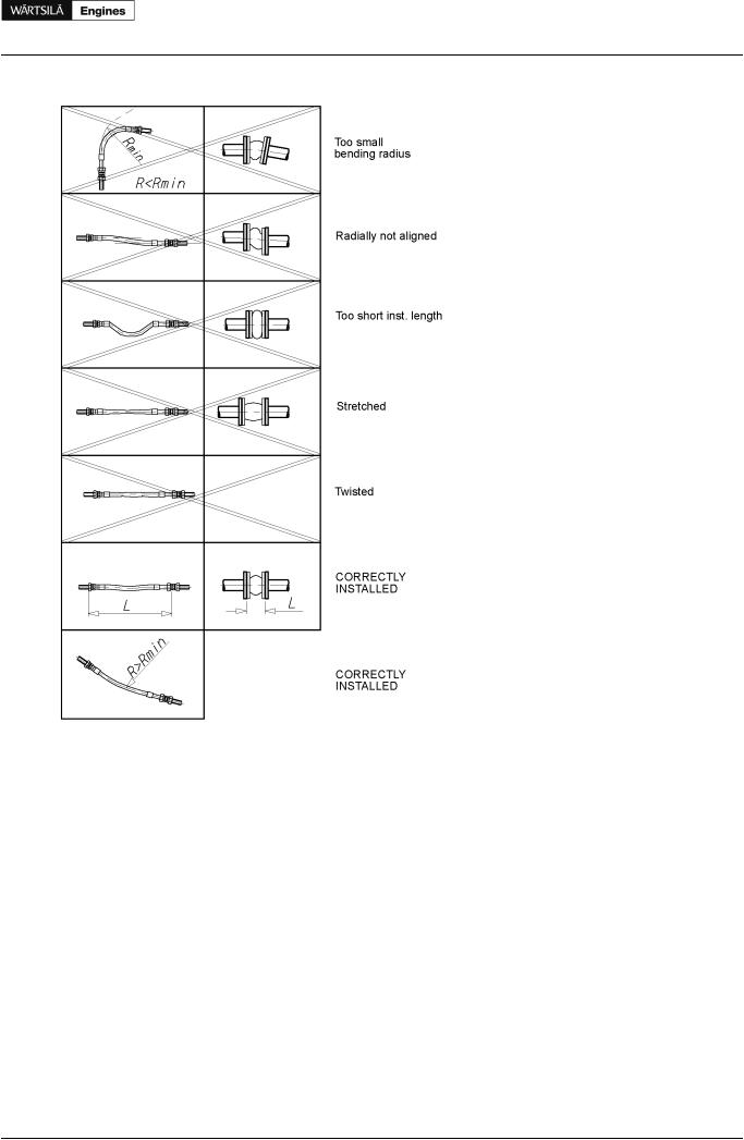
Figure 5.1 Flexible hoses (4V60B0100a)
5.9Clamping of pipes
It is very important to fix the pipes to rigid structures next to flexible pipe connections in order to prevent damage caused by vibration. The following guidelines should be applied:
•Pipe clamps and supports next to the engine must be very rigid and welded to the steel structure of the foundation.
•The first support should be located as close as possible to the flexible connection. Next support should be 0.3-0.5 m from the first support.
•First three supports closest to the engine or generating set should be fixed supports. Where necessary, sliding supports can be used after these three fixed supports to allow thermal expansion of the pipe.
•Supports should never be welded directly to the pipe. Either pipe clamps or flange supports should be used for flexible connection.
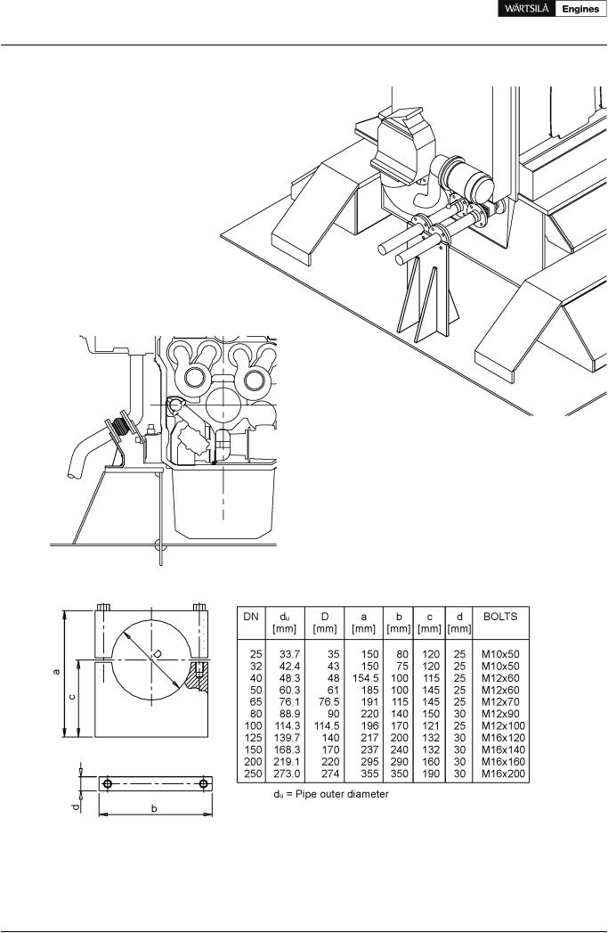
Examples of flange support structures are shown in Figure 5.2. A typical pipe clamp for a fixed support is shown in Figure 5.3. Pipe clamps must be made of steel; plastic clamps or similar may not be used.
Product Guide Wärtsilä 20 - 3/2009 |
27 |
Product Guide
5. Piping Design, Treatment and Installation
Figure 5.2 Flange supports of flexible pipe connections (4V60L0796)
Figure 5.3 Pipe clamp for fixed support (4V61H0842)
28 |
Product Guide Wärtsilä 20 - 3/2009 |