

Product Guide
8. Compressed Air System
8.Compressed Air System
Compressed air is used to start engines and to provide actuating energy for safety and control devices. The use of starting air for other purposes is limited by the classification regulations.
To ensure the functionality of the components in the compressed air system, the compressed air has to be free from solid particles and oil.
8.1Internal compressed air system
The engine is equipped with a pneumatic starting motor driving the engine through a gear rim on the flywheel.
The compressed air system of the electro-pneumatic overspeed trip is connected to the starting air system. For this reason, the air supply to the engine must not be closed during operation.
The nominal starting air pressure of 3 MPa (30 bar) is reduced to 0.8 MPa (8 bar) with a pressure regulator mounted on the engine.
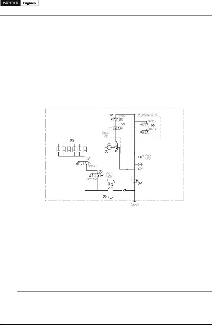
Figure 8.1 Internal starting air system (DAAE060387a)
System components: |
|
|
|
01 |
Turbine starter |
05 |
Air container |
02 |
Blocking valve, when turning gear engaged |
06 |
Solenoid valve |
03 |
Pneumatic cylinder at each injection pump |
07 |
Safety valve |
04 |
Pressure regulator |
08 |
Solenoid valves for air waste gate (if air waste gate) |
Sensors and indicators:
PT301 Starting air pressure, engine inlet PT311 Control air pressure, engine inlet GS792 Turning gear position
CV153-1 Stop solenoid 1
CV153-2 Stop solenoid 2 CV321 Starting solenoid CV657-1 Air waste gate control 1 CV657-2 Air waste gate control 2
Pipe connections |
Size |
Pressure class |
Standard |
|
301 |
Starting air inlet, 3MPa |
OD28 |
PN100 |
DIN 2353 |
Product Guide Wärtsilä 20 - 3/2009 |
61 |
Product Guide
8. Compressed Air System
8.2External compressed air system
The design of the starting air system is partly determined by classification regulations. Most classification societies require that the total capacity is divided into two equally sized starting air receivers and starting air compressors. The requirements concerning multiple engine installations can be subject to special consideration by the classification society.
The starting air pipes should always be slightly inclined and equipped with manual or automatic draining at the lowest points.
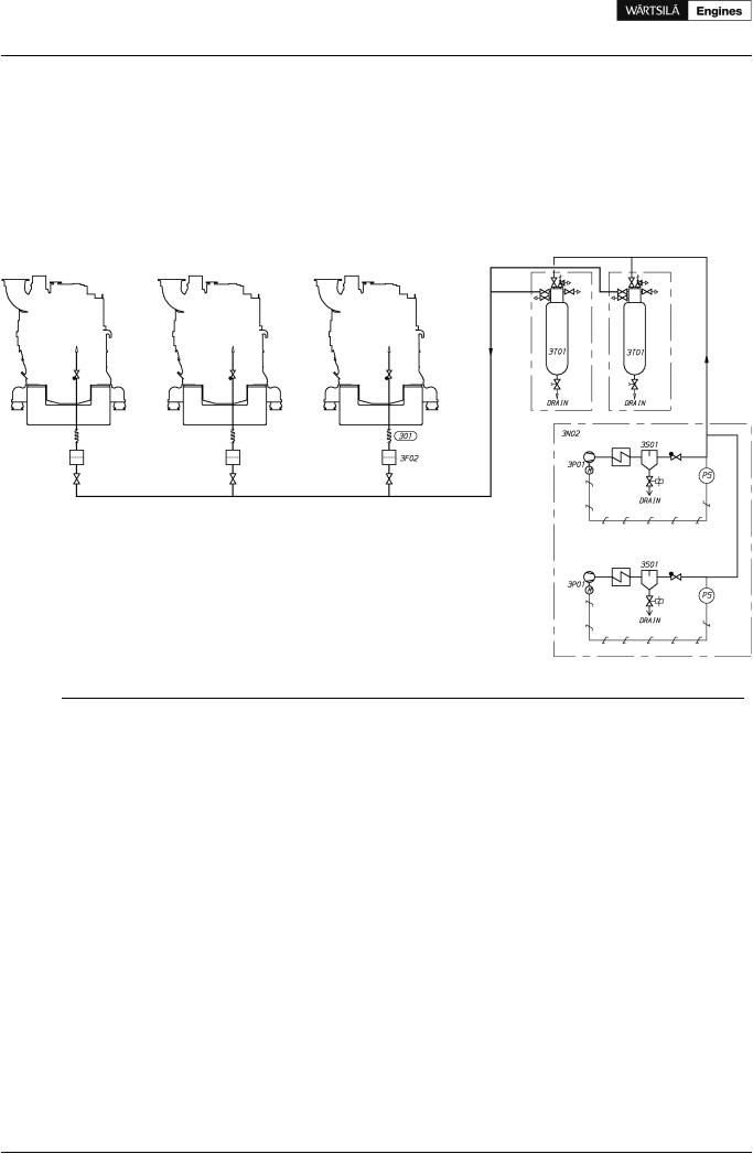
Figure 8.2 External starting air system (DAAE007204d)
System components |
Pipe connections |
|
3F02 |
Air filter (Starting air inlet) |
301 Starting air inlet |
3N02 |
Starting air compressor unit |
|
3P01 |
Compressor (Starting air compressor unit) |
|
3S01 |
Separator (Starting air compressor unit) |
|
3T01 |
Starting air vessel |
|
8.2.1 Starting air compressor unit (3N02)
At least two starting air compressors must be installed. It is recommended that the compressors are capable of filling the starting air vessel from minimum (1.8 MPa) to maximum pressure in 15...30 minutes. For exact determination of the minimum capacity, the rules of the classification societies must be followed.
8.2.2 Oil and water separator (3S01)
An oil and water separator should always be installed in the pipe between the compressor and the air vessel. Depending on the operation conditions of the installation, an oil and water separator may be needed in the pipe between the air vessel and the engine.
8.2.3 Starting air vessel (3T01)
The starting air vessels should be dimensioned for a nominal pressure of 3 MPa.
The number and the capacity of the air vessels for propulsion engines depend on the requirements of the classification societies and the type of installation.
62 |
Product Guide Wärtsilä 20 - 3/2009 |

Product Guide
8. Compressed Air System
It is recommended to use a minimum air pressure of 1.8 MPa, when calculating the required volume of the vessels.
The starting air vessels are to be equipped with at least a manual valve for condensate drain. If the air vessels are mounted horizontally, there must be an inclination of 3...5° towards the drain valve to ensure efficient draining.
Figure 8.3 Starting air vessel
Size |
|
Dimensions [mm] |
|
Weight |
|
[Litres] |
L1 |
L2 1) |
L3 1) |
D |
[kg] |
|
|
||||
125 |
1807 |
243 |
110 |
324 |
170 |
180 |
1217 |
243 |
110 |
480 |
200 |
250 |
1767 |
243 |
110 |
480 |
274 |
500 |
3204 |
243 |
133 |
480 |
450 |
1) Dimensions are approximate.
The starting air consumption stated in technical data is for a successful start. During a remote start the main starting valve is kept open until the engine starts, or until the max. time for the starting attempt has elapsed. A failed remote start can consume two times the air volume stated in technical data. If the ship has a class notation for unattended machinery spaces, then the starts are to be demonstrated as remote starts, usually so that only the last starting attempt is successful.
The required total starting air vessel volume can be calculated using the formula:
where: |
|
VR = |
total starting air vessel volume [m3] |
pE = |
normal barometric pressure (NTP condition) = 0.1 MPa |
VE = |
air consumption per start [Nm3] See Technical data |
n = |
required number of starts according to the classification society |
pRmax = |
maximum starting air pressure = 3 MPa |
pRmin = |
minimum starting air pressure = 1.8 MPa |
NOTE! |
The total vessel volume shall be divided into at least two equally sized starting air vessels. |
Product Guide Wärtsilä 20 - 3/2009 |
63 |

Product Guide
8. Compressed Air System
8.2.4 Starting air filter (3F02)
Condense formation after the water separator (between starting air compressor and starting air vessels) create and loosen abrasive rust from the piping, fittings and receivers. Therefore it is recommended to install a filter before the starting air inlet on the engine to prevent particles to enter the starting air equipment.
An Y-type strainer can be used with a stainless steel screen and mesh size 75 µm. The pressure drop should not exceed 20 kPa (0.2 bar) for the engine specific starting air consumption under a time span of 4 seconds.
The starting air filter is mandatory for W20 engines.
64 |
Product Guide Wärtsilä 20 - 3/2009 |