


Product Guide
15. Foundation
15. Foundation
Engines can be either rigidly mounted on chocks, or resiliently mounted on rubber elements. If resilient mounting is considered, Wärtsilä must be confirmed about excitations such as propeller blade passing frequency. Dynamic forces caused by the engine are listed in chapter Vibration and noise.
15.1 Steel structure design
The system oil tank may not extend under the reduction gear, if the engine is of dry sump type and the oil tank is located beneath the engine foundation. Neither should the tank extend under the support bearing, in case there is a PTO arrangement in the free end. The oil tank must also be symmetrically located in transverse direction under the engine.
The foundation and the double bottom should be as stiff as possible in all directions to absorb the dynamic forces caused by the engine, reduction gear and thrust bearing. The foundation should be dimensioned and designed so that harmful deformations are avoided.
The foundation of the driven equipment must be integrated with the engine foundation.
15.2 Mounting of main engines
15.2.1 Rigid mounting
Main engines can be rigidly mounted to the foundation either on steel chocks or resin chocks.
Prior to installation the shipyard must send detailed plans and calculations of the chocking arrangement to the classification society and to Wärtsilä for approval.
The engine has four feet integrated to the engine block. There are two Ø22 mm holes for M20 holding down bolts and a threaded M16 hole for a jacking screw in each foot. The Ø22 holes in the seating top plate for the holding down bolts can be drilled though the holes in the engine feet. In order to avoid bending stress in the bolts and to ensure proper fastening, the contact face underneath the seating top plate should be counterbored.
Holding down bolts are through-bolts with lock nuts. Selflocking nuts are acceptable, but hot dip galvanized bolts should not be used together with selflocking (nyloc) nuts. Two of the holding down bolts are fitted bolts and the rest are clearance (fixing) bolts. The fixing bolts are M20 8.8 bolts according DIN 931, or equivalent. The two Ø23 H7/m6 fitted bolts are located closest to the flywheel, one on each side of the engine. The fitted bolts must be designed and installed so that a sufficient guiding length in the seating top plate is achieved, if necessary by installing a distance sleeve between the seating top plate and the lower nut. The guiding length in the seating top plate should be at least equal to the bolt diameter. The fitted bolts should be made from a high strength steel, e.g. 42CrMo4 or similar and the bolt should have a reduced shank diameter above the guiding part in order to ensure a proper elongation. The recommended shank diameter for the fitted bolts is 17 mm.
The tensile stress in the bolts is allowed to be max. 80% of the material yield strength and the equivalent stress during tightening should not exceed 90% of the yield strength.
Lateral supports must be installed for all engines. One pair of supports should be located at the free end and one pair (at least) near the middle of the engine. The lateral supports are to be welded to the seating top plate before fitting the chocks. The wedges in the supports are to be installed without clearance, when the engine has reached normal operating temperature. The wedges are then to be secured in position with welds. An acceptable contact surface must be obtained on the wedges of the supports.
Resin chocks
The recommended dimensions of resin chocks are 150 x 400 mm. The total surface pressure on the resin must not exceed the maximum value, which is determined by the type of resin and the requirements of the classification society. It is recommended to select a resin that has a type approval from the relevant classification society for a total surface pressure of 5 N/mm2. (A typical conservative value is ptot 3.5 N/mm2).
During normal conditions, the support face of the engine feet has a maximum temperature of about 75°C, which should be considered when selecting the type of resin.
The bolts must be made as tensile bolts with a reduced shank diameter to ensure sufficient elongation since the bolt force is limited by the permissible surface pressure on the resin. For a given bolt diameter
Product Guide Wärtsilä 20 - 3/2009 |
113 |
Product Guide
15. Foundation
the permissible bolt tension is limited either by the strength of the bolt material (max. stress 80% of the yield strength), or by the maximum permissible surface pressure on the resin.
Steel chocks
The top plates of the foundation girders are to be inclined outwards with regard to the centre line of the engine. The inclination of the supporting surface should be 1/100 and it should be machined so that a contact surface of at least 75% is obtained against the chocks.
Recommended size of the chocks are 115 x 170 mm at the position of the fitted bolts (2 pieces) and 115 x 190 mm at the position of the fixing bolts (6 pieces). The design should be such that the chocks can be removed, when the lateral supports are welded to the foundation and the engine is supported by the jacking screws. The chocks should have an inclination of 1:100 (inwards with regard to the engine centre line). The cut out in the chocks for the fixing bolts shall be 24...26 mm (M20 bolts), while the hole in the chocks for the fitted bolts shall be drilled and reamed to the correct size (ø23 H7) when the engine is finally aligned to the reduction gear.
The design of the holding down bolts is shown in figure Chockingofmainengines(2V69A0238b). The bolts are designed as tensile bolts with a reduced shank diameter to achieve a large elongation, which improves the safety against loosening of the nuts.
Steel chocks with adjustable height
As an alternative to resin chocks or conventional steel chocks it is also permitted to install the engine on adjustable steel chocks. The chock height is adjustable between 30...50 mm for the approved type of chock. There must be a chock of adequate size at the position of each holding down bolt.
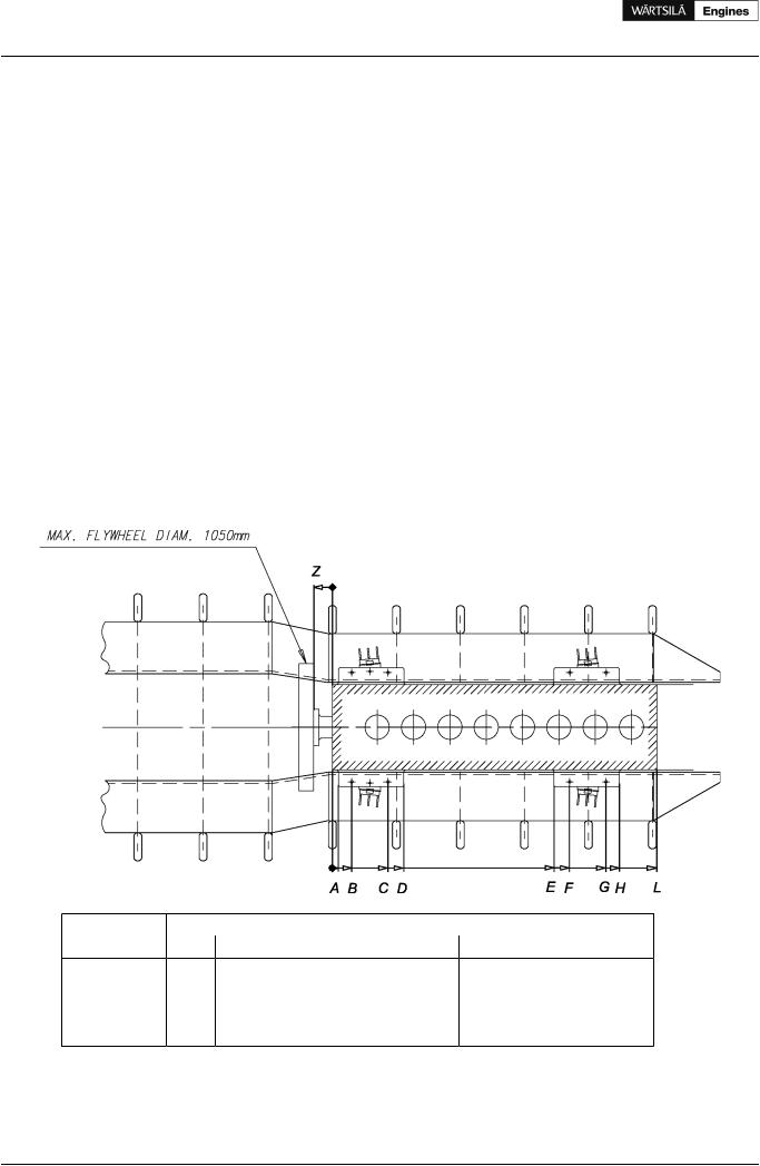
Figure 15.1 Main engine seating, view from above (DAAE017514a)
Engine |
|
|
|
|
Dimensions [mm] |
|
|
|
|
|
|
A |
B |
C |
D |
E |
F |
G |
H |
L |
Z |
W 4L20 |
50 |
160 |
460 |
590 |
930 |
1060 |
1360 |
1470 |
1480 |
155 |
W 6L20 |
50 |
160 |
460 |
590 |
1530 |
1660 |
1960 |
2070 |
2080 |
155 |
W 8L20 |
50 |
160 |
460 |
590 |
1830 |
1960 |
2260 |
2370 |
2680 |
155 |
W 9L20 |
50 |
160 |
460 |
590 |
2130 |
2260 |
2560 |
2670 |
2980 |
155 |
114 |
Product Guide Wärtsilä 20 - 3/2009 |
Product Guide
15. Foundation
Figure 15.2 Main engine seating, side and end view (DAAE017514a)
Engine type |
(D) Deep sump |
(D) Wet sump [mm] (D) Dry sump [mm] |
|
|
[mm] |
|
|
W 4L20 |
- |
400 |
- |
W 6L, 8L, 9L20 |
500 |
300 |
300 |
Figure 15.3 Chocking of main engines (2V69A0238b)
Product Guide Wärtsilä 20 - 3/2009 |
115 |

Product Guide
15. Foundation
15.2.2 Resilient mounting
In order to reduce vibrations and structure borne noise, main engines can be resiliently mounted on rubber mounts. The transmission of forces emitted by a resiliently mounted engine is 10-20% compared to a rigidly mounted engine.
For resiliently mounted engines a speed range of 750-1000 rpm is generally available.
Conical rubber mounts are used in the normal mounting arrangement and additional buffers are thus not required. A different mounting arrangement can be required for wider speed ranges (e.g. FPP installations).
Resilient mounting is not available for W 4L20 engines.
Figure 15.4 Resilient mounting (DAAE003263)
Engine type |
(D) Deep sump |
(D) Wet sump [mm] (D) Dry sump [mm] |
|
|
[mm] |
|
|
W 6L, 8L, 9L20 |
825 |
625 |
625 |
116 |
Product Guide Wärtsilä 20 - 3/2009 |