


Product Guide
3. Technical Data
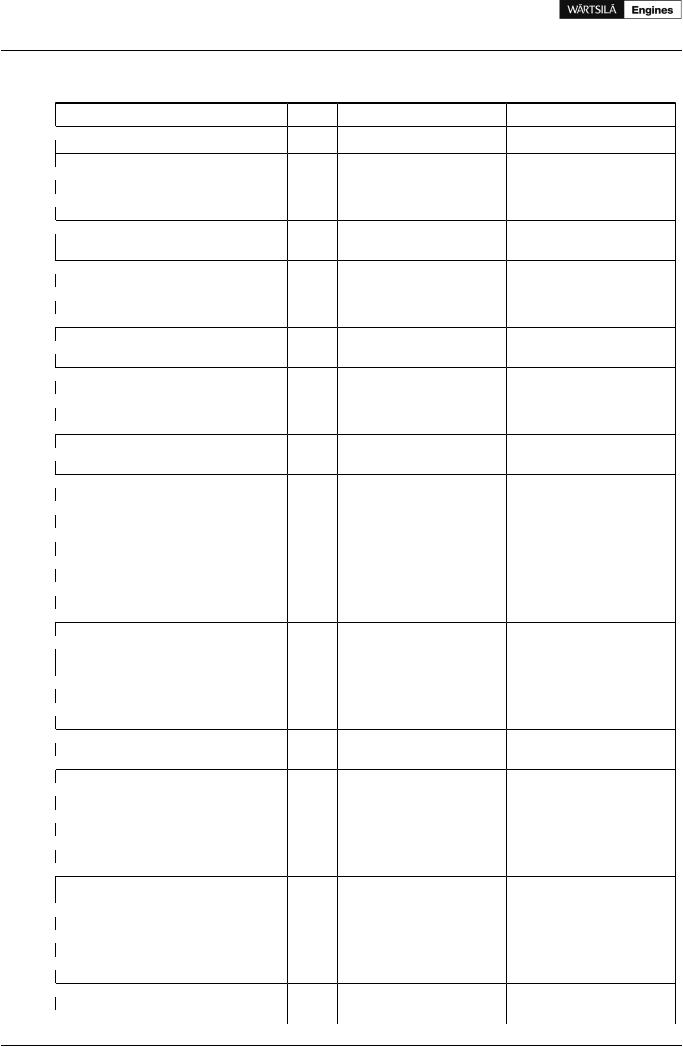
3.3Wärtsilä 8L20
Wärtsilä 8L20
 Cylinder output
Engine speed
Engine output
 Mean effective pressure
 Combustion air system (Note 1)
Flow at 100% load
 Temperature at turbocharger intake, max.
Temperature after air cooler (TE601)
 Exhaust gas system (Note 2)
Flow at 100% load
 Flow at 85% load
Flow at 75% load
 Flow at 50% load
Temperature after turbocharger, 100% load (TE517)
 Temperature after turbocharger, 85% load (TE517)
Temperature after turbocharger, 75% load (TE517)
 Temperature after turbocharger, 50% load (TE517)
Backpressure, max.
 Calculated pipe diameter for 35 m/s
 Heat balance (Note 3)
Jacket water, HT-circuit
 Charge air, LT-circuit
Lubricating oil, LT-circuit
 Radiation
 Fuel system (Note 4)
Pressure before injection pumps (PT101)
 Fuel flow to engine, approx.
HFO viscosity before engine
 MDF viscosity, min.
Max. HFO temperature before engine (TE101)
 Fuel consumption at 100% load
Fuel consumption at 85% load
 Fuel consumption at 75% load
Fuel consumption at 50% load
 Clean leak fuel quantity, MDF at 100% load
Clean leak fuel quantity, HFO at 100% load
 Lubricating oil system
Pressure before bearings, nom. (PT201)
 Suction ability main pump, including pipe loss, max.
Priming pressure, nom. (PT201)
 Suction ability priming pump, including pipe loss, max.
Temperature before bearings, nom. (TE201)
 Temperature after engine, approx.
Pump capacity (main), engine driven
 Pump capacity (main), stand-by
Priming pump capacity, 50Hz/60Hz
 Oil volume, wet sump, nom.
Oil volume in separate system oil tank
 Filter fineness, nom.
Oil consumption at 100% load, max.
 Crankcase ventilation backpressure, max. Oil volume in speed governor
 Cooling water system
High temperature cooling water system
 Pressure at engine, after pump, nom. (PT401)
Pressure at engine, after pump, max. (PT401)
 Temperature before cylinder, approx. (TE401)
Temperature after engine, nom.
 Capacity of engine driven pump, nom.
Pressure drop over engine, total
 Pressure drop in external system, max.
|
ME |
ME |
AE/DE |
AE/DE |
AE/DE |
AE/DE |
|
IMO Tier 1 |
IMO Tier 2 |
IMO Tier 1 |
IMO Tier 1 |
IMO Tier 2 |
IMO Tier 2 |
kW |
200 |
200 |
185 |
200 |
185 |
200 |
RPM |
1000 |
1000 |
900 |
1000 |
900 |
1000 |
kW |
1600 |
1600 |
1480 |
1600 |
1480 |
1600 |
MPa |
2.73 |
2.73 |
2.8 |
2.73 |
2.8 |
2.73 |
kg/s |
3.32 |
3.14 |
3.06 |
3.31 |
2.76 |
3.01 |
°C |
45 |
45 |
45 |
45 |
45 |
45 |
°C |
50...70 |
50...70 |
50...70 |
50...70 |
50...70 |
50...70 |
kg/s |
3.42 |
3.24 |
3.15 |
3.4 |
2.85 |
3.11 |
kg/s |
2.84 |
2.77 |
2.7 |
3.0 |
2.62 |
2.85 |
kg/s |
2.48 |
2.4 |
2.45 |
2.66 |
2.33 |
2.56 |
kg/s |
1.62 |
1.61 |
1.7 |
1.85 |
1.63 |
1.8 |
°C |
320 |
340 |
315 |
320 |
370 |
370 |
°C |
315 |
340 |
310 |
315 |
335 |
335 |
°C |
325 |
350 |
310 |
315 |
335 |
335 |
°C |
385 |
385 |
330 |
335 |
355 |
355 |
kPa |
3.0 |
3.0 |
3.0 |
3.0 |
3.0 |
3.0 |
mm |
456 |
451 |
436 |
455 |
433 |
453 |
kW |
380 |
335 |
320 |
360 |
316 |
330 |
kW |
520 |
550 |
475 |
550 |
489 |
535 |
kW |
250 |
240 |
235 |
260 |
245 |
260 |
kW |
66 |
66 |
62 |
66 |
62 |
66 |
kPa |
700±50 |
700±50 |
700±50 |
700±50 |
700±50 |
700±50 |
m3/h |
1.92 |
1.92 |
1.73 |
1.92 |
1.73 |
1.92 |
cSt |
16... 24 |
16... 24 |
16... 24 |
16... 24 |
16... 24 |
16... 24 |
cSt |
1.8 |
1.8 |
1.8 |
1.8 |
1.8 |
1.8 |
°C |
140 |
140 |
140 |
140 |
140 |
140 |
g/kWh |
196 |
195 |
192 |
196 |
196 |
197 |
g/kWh |
195 |
193 |
191 |
194 |
193 |
194 |
g/kWh |
195 |
193 |
191 |
195 |
194 |
195 |
g/kWh |
200 |
194 |
200 |
202 |
201 |
202 |
kg/h |
6.6 |
6.5 |
5.7 |
6.2 |
6.1 |
6.6 |
kg/h |
1.3 |
1.3 |
1.1 |
1.3 |
1.2 |
1.3 |
kPa |
450 |
450 |
450 |
450 |
450 |
450 |
kPa |
20 |
20 |
20 |
20 |
20 |
20 |
kPa |
80 |
80 |
80 |
80 |
80 |
80 |
kPa |
20 |
20 |
20 |
20 |
20 |
20 |
°C |
66 |
66 |
66 |
66 |
66 |
66 |
°C |
78 |
78 |
78 |
78 |
78 |
78 |
m³/h |
65 |
65 |
45 |
50 |
45 |
50 |
m³/h |
27 |
27 |
27 |
27 |
27 |
27 |
m³/h |
8.6 / 10.5 |
8.6 / 10.5 |
8.6 / 10.5 |
8.6 / 10.5 |
8.6 / 10.5 |
8.6 / 10.5 |
m³ |
0.49 |
0.49 |
0.49 |
0.49 |
0.49 |
0.49 |
m³ |
2.2 |
2.2 |
2.0 |
2.2 |
2.0 |
2.2 |
microns |
25 |
25 |
25 |
25 |
25 |
25 |
g/kWh |
0.5 |
0.5 |
0.5 |
0.5 |
0.5 |
0.5 |
kPa |
0.3 |
0.3 |
0.3 |
0.3 |
0.3 |
0.3 |
liters |
1.4...2.2 |
1.4...2.2 |
1.4...2.2 |
1.4...2.2 |
1.4...2.2 |
1.4...2.2 |
kPa |
200 + static |
200 + static |
200 + static |
200 + static |
200 + static |
200 + static |
kPa |
350 |
350 |
500 |
500 |
500 |
500 |
°C |
83 |
83 |
83 |
83 |
83 |
83 |
°C |
91 |
91 |
91 |
91 |
91 |
91 |
m³/h |
40 |
40 |
39 |
40 |
39 |
40 |
kPa |
90 |
90 |
90 |
90 |
90 |
90 |
kPa |
120 |
120 |
120 |
120 |
120 |
120 |
14 |
Product Guide Wärtsilä 20 - 3/2009 |
Product Guide
3. Technical Data
Wärtsilä 8L20 |
|
ME |
ME |
AE/DE |
AE/DE |
AE/DE |
AE/DE |
|
|
IMO Tier 1 |
IMO Tier 2 |
IMO Tier 1 |
IMO Tier 1 |
IMO Tier 2 |
IMO Tier 2 |
Cylinder output |
kW |
200 |
200 |
185 |
200 |
185 |
200 |
Engine speed |
RPM |
1000 |
1000 |
900 |
1000 |
900 |
1000 |
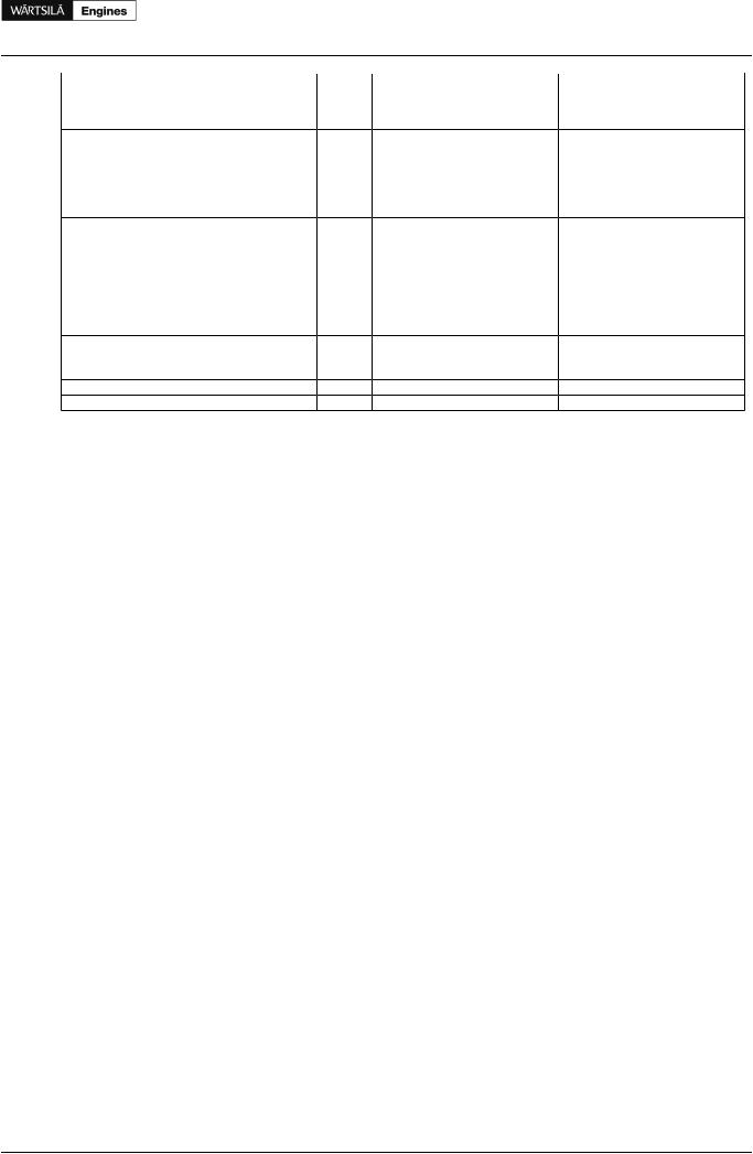
Water volume in engine |
m³ |
0.15 |
0.15 |
0.15 |
0.15 |
0.15 |
0.15 |
Pressure from expansion tank |
kPa |
70...150 |
70...150 |
70...150 |
70...150 |
70...150 |
70...150 |
Low temperature cooling water system |
|
|
|
|
|
|
|
Pressure at engine, after pump, nom. (PT451) |
kPa |
200 + static |
200 + static |
200 + static |
200 + static |
200 + static |
200 + static |
Pressure at engine, after pump, max. (PT451) |
kPa |
350 |
350 |
500 |
500 |
500 |
500 |
Temperature before engine, min...max |
°C |
25...38 |
25...38 |
25...38 |
25...38 |
25...38 |
25...38 |
Capacity of engine driven pump, nom. |
m³/h |
48 |
48 |
45 |
48 |
45 |
48 |
Pressure drop over charge air cooler |
kPa |
30 |
30 |
30 |
30 |
30 |
30 |
Pressure drop over oil cooler |
kPa |
30 |
30 |
30 |
30 |
30 |
30 |
Pressure drop in external system, max. |
kPa |
120 |
120 |
120 |
120 |
120 |
120 |
Pressure from expansion tank |
kPa |
70...150 |
70...150 |
70...150 |
70...150 |
70...150 |
70...150 |
Starting air system |
|
|
|
|
|
|
|
Pressure, nom. |
kPa |
3000 |
3000 |
3000 |
3000 |
3000 |
3000 |
Pressure, max. |
kPa |
3000 |
3000 |
3000 |
3000 |
3000 |
3000 |
Low pressure limit in air vessels |
kPa |
1800 |
1800 |
1800 |
1800 |
1800 |
1800 |
Starting air consumption, start (successful manual) |
Nm3 |
0.4 |
0.4 |
0.4 |
0.4 |
0.4 |
0.4 |
Starting air consumption, start (failed remote) |
Nm3 |
1.2 |
1.2 |
1.2 |
1.2 |
1.2 |
1.2 |
Notes:
Note 1 At ISO 3046-1 conditions (ambient air temperature 25°C, LT-water 25°C) and 100% load. Tolerance 5%.
Note 2 At ISO 3046-1 conditions (ambient air temperature 25°C, LT-water 25°C) and 100% load. Flow tolerance 5% and temperature tolerance 15°C.
Note 3 At ISO 3046-1 conditions (ambient air temperature 25°C, LT-water 25°C) and 100% load. Tolerance for cooling water heat 10%, tolerance for radiation heat 30%. Fouling factors and a margin to be taken into account when dimensioning heat exchangers.
Note 4 According to ISO 3046/1, lower calorific value 42 700 kJ/kg, with engine driven pumps. Tolerance 5%. Load according to propeller law for mechanical propulsion engines (ME).
ME = Engine driving propeller, variable speed
AE = Auxiliary engine driving generator
DE = Diesel-Electric engine driving generator
Subject to revision without notice.
Product Guide Wärtsilä 20 - 3/2009 |
15 |
Product Guide
3. Technical Data
3.4Wärtsilä 9L20
Wärtsilä 9L20
 Cylinder output
Engine speed
Engine output
 Mean effective pressure
 Combustion air system (Note 1)
Flow at 100% load
 Temperature at turbocharger intake, max.
Temperature after air cooler (TE601)
 Exhaust gas system (Note 2)
Flow at 100% load
 Flow at 85% load
Flow at 75% load
 Flow at 50% load
Temperature after turbocharger, 100% load (TE517)
 Temperature after turbocharger, 85% load (TE517)
Temperature after turbocharger, 75% load (TE517)
 Temperature after turbocharger, 50% load (TE517)
Backpressure, max.
 Calculated pipe diameter for 35 m/s
 Heat balance (Note 3)
Jacket water, HT-circuit
 Charge air, LT-circuit
Lubricating oil, LT-circuit
 Radiation
 Fuel system (Note 4)
Pressure before injection pumps (PT101)
 Fuel flow to engine, approx.
HFO viscosity before engine
 MDF viscosity, min.
Max. HFO temperature before engine (TE101)
 Fuel consumption at 100% load
Fuel consumption at 85% load
 Fuel consumption at 75% load
Fuel consumption at 50% load
 Clean leak fuel quantity, MDF at 100% load
Clean leak fuel quantity, HFO at 100% load
 Lubricating oil system
Pressure before bearings, nom. (PT201)
 Suction ability main pump, including pipe loss, max.
Priming pressure, nom. (PT201)
 Suction ability priming pump, including pipe loss, max.
Temperature before bearings, nom. (TE201)
 Temperature after engine, approx.
Pump capacity (main), engine driven
 Pump capacity (main), stand-by
Priming pump capacity, 50Hz/60Hz
 Oil volume, wet sump, nom.
Oil volume in separate system oil tank
 Filter fineness, nom.
Oil consumption at 100% load, max.
 Crankcase ventilation backpressure, max. Oil volume in speed governor
 Cooling water system
High temperature cooling water system
 Pressure at engine, after pump, nom. (PT401)
Pressure at engine, after pump, max. (PT401)
 Temperature before cylinder, approx. (TE401)
Temperature after engine, nom.
 Capacity of engine driven pump, nom.
Pressure drop over engine, total
 Pressure drop in external system, max.
|
ME |
ME |
AE/DE |
AE/DE |
AE/DE |
AE/DE |
|
IMO Tier 1 |
IMO Tier 2 |
IMO Tier 1 |
IMO Tier 1 |
IMO Tier 2 |
IMO Tier 2 |
kW |
200 |
200 |
185 |
200 |
185 |
200 |
RPM |
1000 |
1000 |
900 |
1000 |
900 |
1000 |
kW |
1800 |
1800 |
1665 |
1800 |
1665 |
1800 |
MPa |
2.73 |
2.73 |
2.8 |
2.73 |
2.8 |
2.73 |
kg/s |
3.79 |
3.72 |
3.5 |
3.79 |
3.17 |
3.52 |
°C |
45 |
45 |
45 |
45 |
45 |
45 |
°C |
50...70 |
50...70 |
50...70 |
50...70 |
50...70 |
50...70 |
kg/s |
3.9 |
3.72 |
3.6 |
3.9 |
3.27 |
3.57 |
kg/s |
3.3 |
3.18 |
3.1 |
3.4 |
3.01 |
3.27 |
kg/s |
2.95 |
2.76 |
2.8 |
3.1 |
2.67 |
2.94 |
kg/s |
1.95 |
1.85 |
1.93 |
2.1 |
1.87 |
2.06 |
°C |
310 |
325 |
305 |
310 |
355 |
355 |
°C |
300 |
320 |
295 |
300 |
320 |
320 |
°C |
305 |
330 |
290 |
295 |
320 |
320 |
°C |
355 |
350 |
300 |
305 |
340 |
340 |
kPa |
3.0 |
3.0 |
3.0 |
3.0 |
3.0 |
3.0 |
mm |
483 |
478 |
462 |
483 |
459 |
479 |
kW |
390 |
380 |
360 |
390 |
356 |
375 |
kW |
590 |
610 |
550 |
590 |
557 |
610 |
kW |
270 |
255 |
250 |
270 |
254 |
270 |
kW |
74 |
74 |
68 |
74 |
68 |
74 |
kPa |
700±50 |
700±50 |
700±50 |
700±50 |
700±50 |
700±50 |
m3/h |
1.92 |
1.92 |
1.73 |
1.92 |
1.73 |
1.92 |
cSt |
16... 24 |
16... 24 |
16... 24 |
16... 24 |
16... 24 |
16... 24 |
cSt |
1.8 |
1.8 |
1.8 |
1.8 |
1.8 |
1.8 |
°C |
140 |
140 |
140 |
140 |
140 |
140 |
g/kWh |
192 |
193 |
191 |
192 |
194 |
195 |
g/kWh |
189 |
190 |
190 |
191 |
192 |
193 |
g/kWh |
190 |
190 |
191 |
192 |
193 |
194 |
g/kWh |
196 |
192 |
199 |
200 |
199 |
200 |
kg/h |
6.5 |
7.3 |
6.0 |
6.5 |
6.8 |
7.3 |
kg/h |
1.3 |
1.5 |
1.2 |
1.3 |
1.4 |
1.5 |
kPa |
450 |
450 |
450 |
450 |
450 |
450 |
kPa |
20 |
20 |
20 |
20 |
20 |
20 |
kPa |
80 |
80 |
80 |
80 |
80 |
80 |
kPa |
20 |
20 |
20 |
20 |
20 |
20 |
°C |
66 |
66 |
66 |
66 |
66 |
66 |
°C |
78 |
78 |
78 |
78 |
78 |
78 |
m³/h |
65 |
65 |
45 |
50 |
45 |
50 |
m³/h |
30 |
30 |
30 |
30 |
30 |
30 |
m³/h |
8.6 / 10.5 |
8.6 / 10.5 |
8.6 / 10.5 |
8.6 / 10.5 |
8.6 / 10.5 |
8.6 / 10.5 |
m³ |
0.55 |
0.55 |
0.55 |
0.55 |
0.55 |
0.55 |
m³ |
2.4 |
2.4 |
2.2 |
2.4 |
2.2 |
2.4 |
microns |
25 |
25 |
25 |
25 |
25 |
25 |
g/kWh |
0.5 |
0.5 |
0.5 |
0.5 |
0.5 |
0.5 |
kPa |
0.3 |
0.3 |
0.3 |
0.3 |
0.3 |
0.3 |
liters |
1.4...2.2 |
1.4...2.2 |
1.4...2.2 |
1.4...2.2 |
1.4...2.2 |
1.4...2.2 |
kPa |
200 + static |
200 + static |
200 + static |
200 + static |
200 + static |
200 + static |
kPa |
350 |
350 |
500 |
500 |
500 |
500 |
°C |
83 |
83 |
83 |
83 |
83 |
83 |
°C |
91 |
91 |
91 |
91 |
91 |
91 |
m³/h |
45 |
45 |
44 |
45 |
44 |
45 |
kPa |
90 |
90 |
90 |
90 |
90 |
90 |
kPa |
120 |
120 |
120 |
120 |
120 |
120 |
16 |
Product Guide Wärtsilä 20 - 3/2009 |
Product Guide
3. Technical Data
Wärtsilä 9L20 |
|
ME |
ME |
AE/DE |
AE/DE |
AE/DE |
AE/DE |
|
|
IMO Tier 1 |
IMO Tier 2 |
IMO Tier 1 |
IMO Tier 1 |
IMO Tier 2 |
IMO Tier 2 |
Cylinder output |
kW |
200 |
200 |
185 |
200 |
185 |
200 |
Engine speed |
RPM |
1000 |
1000 |
900 |
1000 |
900 |
1000 |
Water volume in engine |
m³ |
0.16 |
0.16 |
0.16 |
0.16 |
0.16 |
0.16 |
Pressure from expansion tank |
kPa |
70...150 |
70...150 |
70...150 |
70...150 |
70...150 |
70...150 |
Low temperature cooling water system |
|
|
|
|
|
|
|
Pressure at engine, after pump, nom. (PT451) |
kPa |
200 + static |
200 + static |
200 + static |
200 + static |
200 + static |
200 + static |
Pressure at engine, after pump, max. (PT451) |
kPa |
350 |
350 |
500 |
500 |
500 |
500 |
Temperature before engine, min...max |
°C |
25...38 |
25...38 |
25...38 |
25...38 |
25...38 |
25...38 |
Capacity of engine driven pump, nom. |
m³/h |
54 |
54 |
50 |
54 |
50 |
54 |
Pressure drop over charge air cooler |
kPa |
30 |
30 |
30 |
30 |
30 |
30 |
Pressure drop over oil cooler |
kPa |
30 |
30 |
30 |
30 |
30 |
30 |
Pressure drop in external system, max. |
kPa |
120 |
120 |
120 |
120 |
120 |
120 |
Pressure from expansion tank |
kPa |
70...150 |
70...150 |
70...150 |
70...150 |
70...150 |
70...150 |
Starting air system |
|
|
|
|
|
|
|
Pressure, nom. |
kPa |
3000 |
3000 |
3000 |
3000 |
3000 |
3000 |
Pressure, max. |
kPa |
3000 |
3000 |
3000 |
3000 |
3000 |
3000 |
Low pressure limit in air vessels |
kPa |
1800 |
1800 |
1800 |
1800 |
1800 |
1800 |
Starting air consumption, start (successful manual) |
Nm3 |
0.4 |
0.4 |
0.4 |
0.4 |
0.4 |
0.4 |
Starting air consumption, start (failed remote) |
Nm3 |
1.2 |
1.2 |
1.2 |
1.2 |
1.2 |
1.2 |
Notes:
Note 1 At ISO 3046-1 conditions (ambient air temperature 25°C, LT-water 25°C) and 100% load. Tolerance 5%.
Note 2 At ISO 3046-1 conditions (ambient air temperature 25°C, LT-water 25°C) and 100% load. Flow tolerance 5% and temperature tolerance 15°C.
Note 3 At ISO 3046-1 conditions (ambient air temperature 25°C, LT-water 25°C) and 100% load. Tolerance for cooling water heat 10%, tolerance for radiation heat 30%. Fouling factors and a margin to be taken into account when dimensioning heat exchangers.
Note 4 According to ISO 3046/1, lower calorific value 42 700 kJ/kg, with engine driven pumps. Tolerance 5%. Load according to propeller law for mechanical propulsion engines (ME).
ME = Engine driving propeller, variable speed
AE = Auxiliary engine driving generator
DE = Diesel-Electric engine driving generator
Subject to revision without notice.
Product Guide Wärtsilä 20 - 3/2009 |
17 |