

Product Guide
14. Automation System
14.2 UNIC C2
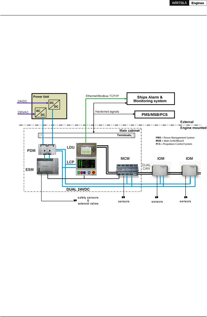
UNIC C2 is a fully embedded and distributed engine management system, which handles all control functions on the engine; for example start sequencing, start blocking, speed control, load sharing, normal stops and safety shutdowns.
The distributed modules communicate over a CAN-bus. CAN is a communication bus specifically developed for compact local networks, where high speed data transfer and safety are of utmost importance.
The CAN-bus and the power supply to each module are both physically doubled on the engine for full redundancy.
Control signals to/from external systems are hardwired to the terminals in the main cabinet on the engine. Process data for alarm and monitoring are communicated over an Modbus TCP connection to external systems.
Figure 14.7 Architecture of UNIC C2
Equipment in the main cabinet on the engine:
MCM |
Main Control Module handles all strategic control functions, for example start sequencing, start |
|
blocking and speed/load control. |
ESM |
Engine Safety Module handles fundamental engine safety, for example shutdown due to overspeed |
|
or low lubricating oil pressure. The safety module is the interface to the shutdown devices on the |
|
engine for all other control equipment. |
LCP |
Local Control Panel is equipped with push buttons and switches for local engine control, as well as |
|
indication of running hours and safety-critical operating parameters. |
LDU |
Local Display Unit offers a set of menus for retrieval and graphical display of operating data, calculated |
|
data and event history. The module also handles communication with external systems over Modbus |
|
TCP. |
PDM |
PowerDistributionModulehandlesfusing,powerdistribution,earthfaultmonitoringandEMCfiltration |
|
in the system. It provides two fully redundant 24 VDC supplies to all modules, sensors and control |
|
devices. |
Equipment locally on the engine: |
|
IOM |
Input/Output Module handles measurements and limited control functions in a specific area on the |
|
engine. |
Sensors |
|
104 Product Guide Wärtsilä 20 - 3/2009
Product Guide
14. Automation System
Solenoids
Actuators
The above equipment is prewired on the engine. The ingress protection class is IP54.
External equipment
Power unit
Two redundant power supply converters/isolators are installed in a steel sheet cabinet for bulkhead mounting, protection class IP44.
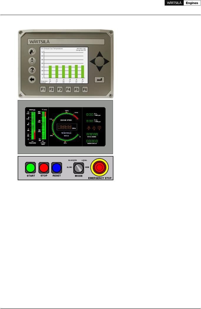
14.2.1 Local control panel and local display unit
Operational functions available at the LCP:
•Local start
•Local stop
•Local emergency stop
•Local shutdown reset
•Local mode selector switch with positions blow, blocked, local and remote Positions:
-Local: Engine start and stop can be done only at the local control panel
-Remote: Engine can be started and stopped only remotely
-Blow: In this position it is possible to perform a “blow” (an engine rotation check with indicator valves open and disabled fuel injection) by the start button
-Blocked: Normal start of the engine is not possible
The LCP has back-up indication of the following parameters:
•Engine speed
•Turbocharger speed
•Running hours
•Lubricating oil pressure
•HT cooling water temperature
The local display unit has a set of menus for retrieval and graphical display of operating data, calculated data and event history.
Product Guide Wärtsilä 20 - 3/2009 |
105 |
Product Guide
14. Automation System
Figure 14.8 Local control panel and local display unit
14.2.2 Engine safety system
The engine safety system is based on hardwired logic with redundant design for safety-critical functions. The engine safety module handles fundamental safety functions, for example overspeed protection. It is also the interface to the shutdown devices on the engine for all other parts of the control system.
Main features:
•Redundant design for power supply, speed inputs and stop solenoid control
•Fault detection on sensors, solenoids and wires
•Led indication of status and detected faults
•Digital status outputs
•Shutdown latching and reset
•Shutdown pre-warning
•Shutdown override (configuration depending on application)
•Analogue outputs for engine speed and turbocharger speed
•Adjustable speed switches
106 |
Product Guide Wärtsilä 20 - 3/2009 |
Product Guide
14. Automation System
14.2.3 Power unit
A power unit is delivered with each engine for separate installation. The power unit supplies DC power to the electrical system on the engine and provides isolation from other DC systems onboard. The cabinet is designed for bulkhead mounting, protection degree IP44, max. ambient temperature 50 °C.
The power unit contains redundant power converters, each converter dimensioned for 100% load. At least one of the two incoming supplies must be connected to a UPS. The power unit supplies the equipment on the engine with 2 x 24 VDC.
Power supply from ship's system:
•Supply 1: 230 VAC / abt. 150 W
•Supply 2: 24 VDC / abt. 150 W.
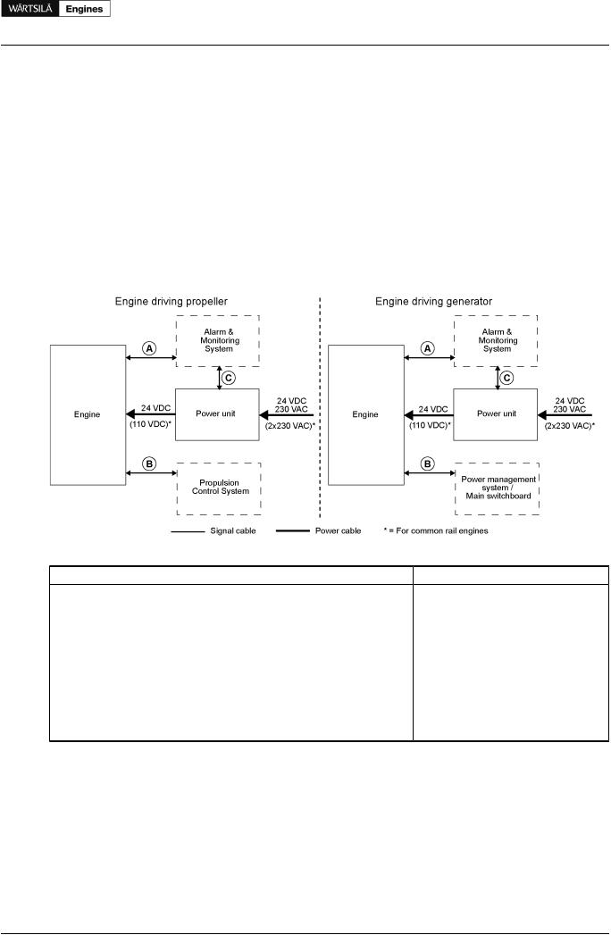
14.2.4Cabling and system overview
Figure 14.9 UNIC C2 overview
Table 14.2 Typical amount of cables for UNIC C2 |
|
|
Cable |
From <=> To |
Cable types (typical) |
A |
Engine <=> alarm & monitoring system |
3 x 2 x 0.75 mm2 |
|
|
1 x Ethernet CAT 5 |
B |
Engine <=> propulsion control system |
1 x 2 x 0.75 mm2 |
|
Engine <=> power management system / main switchboard |
1 x 2 x 0.75 mm2 |
|
|
1 x 2 x 0.75 mm2 |
|
|
14 x 0.75 mm2 |
|
|
14 x 0.75 mm2 |
C |
Power unit <=> alarm & monitoring system |
2 x 0.75 mm2 |
D |
Engine <=> power unit |
2 x 2.5 mm2 (power supply) |
|
|
2 x 2.5 mm2 (power supply) |
NOTE! |
Cable types and grouping of signals in different cables will differ depending on installation and |
|
|
cylinder configuration. |
|
Power supply requirements are specified in section Power unit.
Product Guide Wärtsilä 20 - 3/2009 |
107 |
Product Guide
14. Automation System
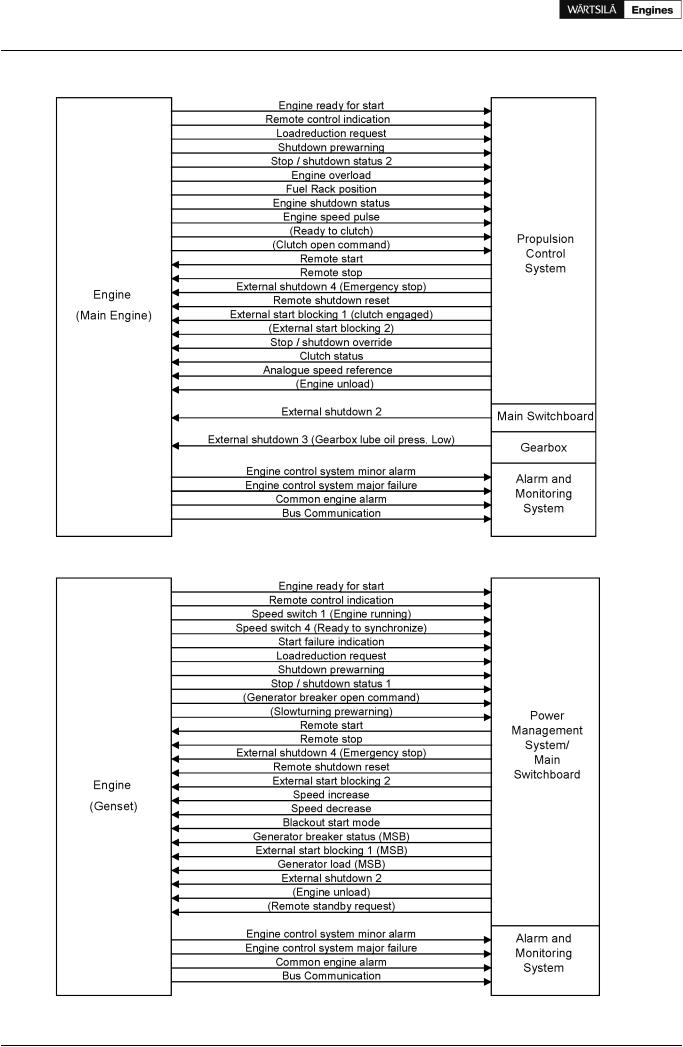
Figure 14.10 Signal overview (Main engine)
Figure 14.11 Signal overview (Generating set)
108 |
Product Guide Wärtsilä 20 - 3/2009 |