


Product Guide
7. Lubricating Oil System
7.Lubricating Oil System
7.1Lubricating oil requirements
7.1.1 Engine lubricating oil
The lubricating oil must be of viscosity class SAE 40 and have a viscosity index (VI) of minimum 95. The lubricating oil alkalinity (BN) is tied to the fuel grade, as shown in the table below. BN is an abbreviation of Base Number. The value indicates milligrams KOH per gram of oil.
Table 7.1 Fuel standards and lubricating oil requirements |
|
||
Category |
Fuel standard |
|
Lubricating oil BN |
A |
ASTM D 975-01, |
GRADE NO. 1-D, 2-D |
|
|
BS MA 100: 1996 |
DMX, DMA |
10...30 |
|
CIMAC 2003 |
DX, DA |
|
|
|
||
|
ISO8217: 1996(E) |
ISO-F-DMX, DMA |
|
B |
BS MA 100: 1996 |
DMB |
|
|
CIMAC 2003 |
DB |
15...30 |
|
ISO 8217: 1996(E) |
ISO-F-DMB |
|
C |
ASTM D 975-01, |
GRADE NO. 4-D |
|
|
ASTM D 396-04, |
GRADE NO. 5-6 |
|
|
BS MA 100: 1996 |
DMC, RMA10-RMK55 |
30...55 |
|
CIMAC 2003 |
DC, A30-K700 |
|
|
ISO 8217: 1996(E) |
ISO-F-DMC, RMA10-RMK55 |
|
F |
LIQUID BIO FUEL (LBF) |
|
10...20 |
BN 50-55 lubricants are to be selected in the first place for operation on HFO. BN 40 lubricants can also be used with HFO provided that the sulphur content of the fuel is relatively low, and the BN remains above the condemning limit for acceptable oil change intervals. BN 30 lubricating oils should be used together with HFO only in special cases; for example in SCR (Selective Catalyctic Reduction) installations, if better total economy can be achieved despite shorter oil change intervals. Lower BN may have a positive influence on the lifetime of the SCR catalyst.
Crude oils with low sulphur content may permit the use of BN 30 lubricating oils. It is however not unusual that crude oils contain other acidic compounds, which requires a high BN oil although the sulphur content of the fuel is low.
It is not harmful to the engine to use a higher BN than recommended for the fuel grade.
Different oil brands may not be blended, unless it is approved by the oil suppliers. Blending of different oils must also be approved by Wärtsilä, if the engine still under warranty.
An updated list of approved lubricating oils is supplied for every installation.
7.1.2 Oil in speed governor or actuator
An oil of viscosity class SAE 30 or SAE 40 is acceptable in normal operating conditions. Usually the same oil as in the engine can be used. At low ambient temperatures it may be necessary to use a multigrade oil (e.g. SAE 5W-40) to ensure proper operation during start-up with cold oil.
Product Guide Wärtsilä 20 - 3/2009 |
51 |
Product Guide
7. Lubricating Oil System
7.2Internal lubricating oil system
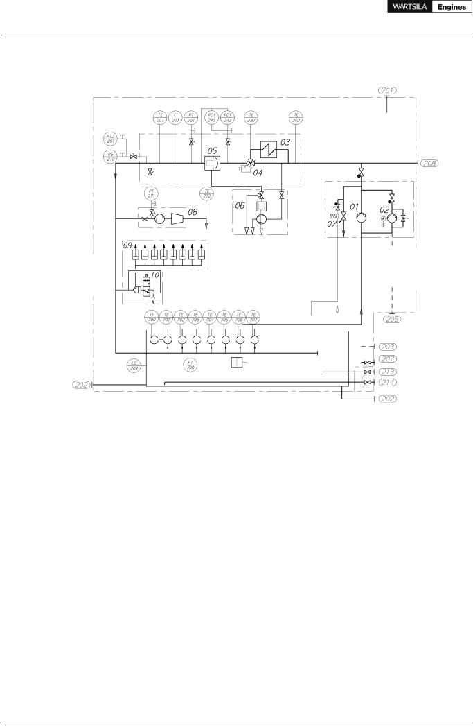
Figure 7.1 Internal lubricating oil system (DAAE060386b)
System components:
01 Lubricating oil main pump
02 Prelubricating oil pump
03 Lubricating oil cooler
04 Thermostatic valve
05 Automatic filter
Sensors and indicators:
PT201 Lubricating oil pressure, engine inlet PTZ201 Lubricating oil pressure, engine inlet
PS210 Lubricating oil pressure switch, standby pump PDT243 Lubricating oil filter pressure difference PDI243 Lubricating oil filter pressure difference PT271 Lubricating oil pressure, TC inlet (if ME) PT700 Crankcase pressure (if FAKS/CBM)
06 Centrifugal filter
07 Pressure control valve
08 Turbocharger
09Guide block (if VIC)
10Control valve (if VIC)
TE201 Lubricating oil temp., engine inlet TI201 Lubricating oil temp., engine inlet (if ME)
TE202 Lubricating oil temp., engine outlet (if FAKS/CBM) TE232 Lubricating oil temp., oil cooler outlet (if FAKS/CBM) TE272 Lubricating oil temp., TC outlet (if ME)
TE70# Main bearing temp. (option)
LS204 Lubricating oil low level, oil sump (if wet sump)
52 |
Product Guide Wärtsilä 20 - 3/2009 |

Product Guide
7. Lubricating Oil System
Pipe connections |
Size |
Pressure class |
Standard |
|
202 |
Lubricating oil outlet (if dry sump) |
DN100 |
See figure 7.2 |
|
203 |
Lubricating oil to engine driven pump (if dry sump) |
DN100 |
See figure 7.2 |
|
205 |
Lubricating oil to priming pump (if dry sump) |
DN32 |
PN40 |
ISO 7005-1 |
207 |
Lubricating oil to electric driven pump (if stand-by pump) |
DN100 |
PN16 |
ISO 7005-1 |
208 |
Lub. oil from electric driven pump (if stand-by pump) |
DN80 |
PN16 |
ISO 7005-1 |
213 |
Lubricating oil from separator and filling |
DN32 |
PN40 |
ISO 7005-1 |
214 |
Lubricating oil to separator and drain |
DN32 |
PN40 |
ISO 7005-1 |
701 |
Crankcase air vent |
DN65 |
|
|
Figure 7.2 Flange for connections 202, 203, dry sump (4V32A0506a)
The lubricating oil sump is of wet sump type for auxiliary and diesel-electric engines. Dry sump is recommended for main engines operating on HFO. The dry sump type has two oil outlets at each end of the engine. Two of the outlets shall be connected to the system oil tank.
The direct driven lubricating oil pump is of gear type and equipped with a pressure control valve. The pump is dimensioned to provide sufficient flow even at low speeds. A stand-by pump connection is available as option. Concerning suction height, flow rate and pressure of the pump, see Technical data.
The pre-lubricating pump is an electric motor driven gear pump equipped with a safety valve. The pump should always be running, when the engine is stopped. Concerning suction height, flow rate and pressure of the pump, see Technical data.
The lubricating oil module built on the engine consists of the lubricating oil cooler, thermostatic valve and automatic filter.
The centrifugal filter is installed to clean the back-flushing oil from the automatic filter.
Product Guide Wärtsilä 20 - 3/2009 |
53 |

Product Guide
7. Lubricating Oil System
7.3External lubricating oil system
Figure 7.3 Lubricating oil system, auxiliary engines (3V76E4590b)
System components |
Pipe connections |
||
2E02 |
Heater (Separator unit) |
213 |
Lubricating oil from separator and filling |
2F03 |
Suction filter (Separator unit) |
214 |
Lubricating oil to separator and drain |
2N01 |
Separator unit |
215 |
Lubricating oil filling |
2P03 |
Separator pump (Separator unit) |
701 |
Crankcase air vent |
2S01 |
Separator |
|
|
2S02 |
Condensate trap |
|
|
2T03 |
New oil tank |
|
|
2T04 |
Renovating oil tank |
|
|
2T05 |
Renovated oil tank |
|
|
2T06 |
Sludge tank |
|
|
54 |
Product Guide Wärtsilä 20 - 3/2009 |
Product Guide
7. Lubricating Oil System
Figure 7.4 Lubricating oil system, main engine (3V76E4591d)
System components |
Pipe connections |
2E02 |
Heater (Separator unit) |
2F01 |
Suction strainer (Main lubricating oil pump) |
2F03 |
Suction filter (Separator unit) |
2F04 |
Suction strainer (Prelubricating oil pump) |
2F06 |
Suction strainer (Stand-by pump) |
2N01 |
Separator unit |
2P03 |
Separator pump (Separator unit) |
2P04 |
Stand-by pump |
2S01 |
Separator |
2S02 |
Condensate trap |
2T01 |
System oil tank |
2T06 |
Sludge tank |
202Lubricating oil outlet (from oil sump)
203Lubricating oil to engine driven pump
205Lubricating oil to priming pump
208Lubricating oil from electric driven pump
701Crankcase air vent
7.3.1 Separation system
Separator unit (2N01)
Each engine must have a dedicated lubricating oil separator and the separators shall be dimensioned for continuous separating. If the installation is designed to operate on MDF only, then intermittent separating might be sufficient.
Product Guide Wärtsilä 20 - 3/2009 |
55 |

Product Guide
7. Lubricating Oil System
Generating sets operating on a fuel having a viscosity of max. 380 cSt / 50°C may have a common lubricating oil separator unit. Three engines may have a common lubricating oil separator unit. In installations with four or more engines two lubricating oil separator units should be installed.
Separators are usually supplied as pre-assembled units.
Typically lubricating oil separator units are equipped with:
•Feed pump with suction strainer and safety valve
•Preheater
•Separator
•Control cabinet
The lubricating oil separator unit may also be equipped with an intermediate sludge tank and a sludge pump, which offers flexibility in placement of the separator since it is not necessary to have a sludge tank directly beneath the separator.
Separator feed pump (2P03)
The feed pump must be selected to match the recommended throughput of the separator. Normally the pump is supplied and matched to the separator by the separator manufacturer.
The lowest foreseen temperature in the system oil tank (after a long stop) must be taken into account when dimensioning the electric motor.
Separator preheater (2E02)
The preheater is to be dimensioned according to the feed pump capacity and the temperature in the system oil tank. When the engine is running, the temperature in the system oil tank located in the ship's bottom is normally 65...75°C. To enable separation with a stopped engine the heater capacity must be sufficient to maintain the required temperature without heat supply from the engine.
Recommended oil temperature after the heater is 95°C.
The surface temperature of the heater must not exceed 150°C in order to avoid cooking of the oil.
The heaters should be provided with safety valves and drain pipes to a leakage tank (so that possible leakage can be detected).
Separator (2S01)
The separators should preferably be of a type with controlled discharge of the bowl to minimize the lubricating oil losses.
The service throughput Q [l/h] of the separator can be estimated with the formula:
where:
Q = volume flow [l/h]
P = engine output [kW]
n = number of through-flows of tank volume per day: 5 for HFO, 4 for MDF
t = operating time [h/day]: 24 for continuous separator operation, 23 for normal dimensioning
Sludge tank (2T06)
The sludge tank should be located directly beneath the separators, or as close as possible below the separators, unless it is integrated in the separator unit. The sludge pipe must be continuously falling.
Renovating oil tank (2T04)
In case of wet sump engines the oil sump content can be drained to this tank prior to separation.
56 |
Product Guide Wärtsilä 20 - 3/2009 |

Product Guide
7. Lubricating Oil System
Renovated oil tank (2T05)
This tank contains renovated oil ready to be used as a replacement of the oil drained for separation.
7.3.2 System oil tank (2T01)
Recommended oil tank volume is stated in chapter Technical data.
The system oil tank is usually located beneath the engine foundation. The tank may not protrude under the reduction gear or generator, and it must also be symmetrical in transverse direction under the engine. The location must further be such that the lubricating oil is not cooled down below normal operating temperature. Suction height is especially important with engine driven lubricating oil pump. Losses in strainers etc. add to the geometric suction height. Maximum suction ability of the pump is stated in chapter Technical data.
The pipe connection between the engine oil sump and the system oil tank must be flexible to prevent damages due to thermal expansion. The return pipes from the engine oil sump must end beneath the minimum oil level in the tank. Further on the return pipes must not be located in the same corner of the tank as the suction pipe of the pump.
The suction pipe of the pump should have a trumpet shaped or conical inlet to minimise the pressure loss. For the same reason the suction pipe shall be as short and straight as possible and have a sufficient diameter. A pressure gauge shall be installed close to the inlet of the lubricating oil pump. The suction pipe shall further be equipped with a non-return valve of flap type without spring. The non-return valve is particularly important with engine driven pump and it must be installed in such a position that self-closing is ensured.
Suction and return pipes of the separator must not be located close to each other in the tank.
The ventilation pipe from the system oil tank may not be combined with crankcase ventilation pipes.
It must be possible to raise the oil temperature in the tank after a long stop. In cold conditions it can be necessary to have heating coils in the oil tank in order to ensure pumpability. The separator heater can normally be used to raise the oil temperature once the oil is pumpable. Further heat can be transferred to the oil from the preheated engine, provided that the oil viscosity and thus the power consumption of the pre-lubricating oil pump does not exceed the capacity of the electric motor.
Product Guide Wärtsilä 20 - 3/2009 |
57 |

Product Guide
7. Lubricating Oil System
Figure 7.5 Example of system oil tank arrangement (DAAE007020e)
Design data: |
|
Oil volume |
1.2...1.5 l/kW, see also Technical data |
Oil level at service |
75 - 80 % of tank volume |
Oil level alarm |
60% of tank volume |
7.3.3 New oil tank (2T03)
In engines with wet sump, the lubricating oil may be filled into the engine, using a hose or an oil can, through the crankcase cover or through the separator pipe. The system should be arranged so that it is possible to measure the filled oil volume.
7.3.4 Suction strainers (2F01, 2F04, 2F06)
It is recommended to install a suction strainer before each pump to protect the pump from damage. The suction strainer and the suction pipe must be amply dimensioned to minimize pressure losses. The suction strainer should always be provided with alarm for high differential pressure.
Design data:
Fineness |
0.5...1.0 mm |
58 |
Product Guide Wärtsilä 20 - 3/2009 |