

s90mec7
.pdfMAN B&W |
11.03 |
|
|
|
Page of 2 |
Components for Central Cooling Water System
Seawater cooling pumps
The pumps are to be of the centrifugal type.
Seawater flow...................... |
see ‘List of capacities’ |
||
Pump head.................................................... |
|
2.5 bar |
|
Test pressure.................... |
according to class rules |
||
Working temperature, normal |
......................0 32 |
°C |
|
Working temperature..................... |
|
maximum 50 |
°C |
The capacity is to be within a tolerance of 0% to +10%.
The differential pressure of the pumps is to be determined on the basis of the total actual pressure drop across the cooling water system.
Central cooler
The cooler is to be of the shell and tube or plate heat exchanger type, made of seawater resistant material.
Heat dissipation...................... |
see ‘List of capacities’ |
|
Central cooling water flow....... |
see ‘List of capacities’ |
|
Central cooling water temperature, outlet......... |
36 °C |
|
Pressure drop on central cooling side.....max. 0.2 bar
Seawater flow......................... |
see ‘List of capacities’ |
Seawater temperature, inlet.............................. |
32 °C |
Pressure drop on |
|
seawater side................................ |
maximum 0.2 bar |
The pressure drop may be larger, depending on the actual cooler design.
The heat dissipation and the seawater flow figures are based on MCR output at tropical conditions, i.e. a seawater temperature of 32 °C and an ambient air temperature of 45 °C.
Overload running at tropical conditions will slightly increase the temperature level in the cooling system, and will also slightly influence the engine performance.
Central cooling water pumps
The pumps are to be of the centrifugal type.
Central cooling water flow. |
...see ‘List of capacities’ |
|
Pump head.................................................... |
2.5 bar |
|
Delivery pressure................ |
depends on location of |
|
|
expansion tank |
|
Test pressure.................... |
according to class rules |
|
Working temperature...................................... |
80 |
°C |
Design temperature...................................... |
100 |
°C |
The flow capacity is to be within a tolerance of 0% to +10%.
The list of capacities covers the main engine only. The differential pressure provided by the pumps is to be determined on the basis of the total actual pressure drop across the cooling water system.
Central cooling water thermostatic valve
The low temperature cooling system is to be equipped with a three way valve, mounted as a mixing valve, which by passes all or part of the fresh water around the central cooler.
The sensor is to be located at the outlet pipe from the thermostatic valve and is set so as to keep a temperature level of minimum 10 °C.
MAN B&W MC/MC C, ME/ME-B/ME C/ME GI engines
MAN Diesel |
198 39 87 2.3 |
|

MAN B&W |
11.03 |
|
|
Jacket water system
Due to the central cooler the cooling water inlet temperature is about 4 °C higher for for this system compared to the seawater cooling system.
The input data are therefore different for the scavenge air cooler, the lube oil cooler and the jacket water cooler.
The heat dissipation and the central cooling water flow figures are based on an MCR output at tropical conditions, i.e. a maximum seawater temperature of 32 °C and an ambient air temperature of 45 °C.
Jacket water cooling pump |
|
|
The pumps are to be of the centrifugal type. |
|
|
Jacket water flow................. |
see ‘List of capacities’ |
|
Pump head.................................................... |
3.0 bar |
|
Delivery pressure................ |
depends on location of |
|
|
expansion tank |
|
Test pressure.................... |
according to class rules |
|
Working temperature...................................... |
80 |
°C |
Design temperature...................................... |
100 |
°C |
The flow capacity is to be within a tolerance of 0% to +10%.
The stated of capacities cover the main engine only. The pump head of the pumps is to be determined on the basis of the total actual pressure drop across the cooling water system.
Scavenge air cooler
The scavenge air cooler is an integrated part of the main engine.
Heat dissipation........................ |
see ‘List of capacities’ |
|
Central cooling water flow........ |
see ‘List of capacities’ |
|
Central cooling temperature, inlet..................... |
36 °C |
|
Pressure drop on FW LT water side.... |
approx. 0.5 bar |
|
Page of 2
Lubricating oil cooler
See chapter 8 ‘Lubricating Oil’.
Jacket water cooler
The cooler is to be of the shell and tube or plate heat exchanger type.
Heat dissipation................... |
see ‘List of capacities’ |
|
Jacket water flow................. |
see ‘List of capacities’ |
|
Jacket water temperature, inlet...................... |
80 °C |
|
Pressure drop on jacket water side .... |
max. 0.2 bar |
|
Central cooling water flow.... |
see ‘List of capacities’ |
|
Central cooling water |
|
|
temperature, inlet............................... |
|
approx. 42 °C |
Pressure drop on Central |
|
|
cooling water side................................ |
|
max. 0.2 bar |
The other data for the jacket cooling water system can be found in chapter 12.
For further information about a common cooling water system for main engines and MAN Diesel auxiliary engines, please refer to our publication:
Uni concept Auxiliary Systems for Two stroke Main
The publication is available at www.mandiesel.com under ‘Quicklinks’ → ‘Technical Papers’
MAN B&W MC/MC C, ME/ME-B/ME C/ME GI engines
MAN Diesel |
198 39 87 2.3 |
|

MAN B&W
Seawater
Cooling System
12
MAN Diesel

MAN B&W |
12.01 |
|
|
|
Page of 1 |
Seawater Systems
The water cooling can be arranged in several configurations, the most simple system choices being seawater and central cooling water system:
•A seawater cooling system and a jacket cooling water system
•The advantages of the seawater cooling system are mainly related to first cost, viz:
•Only two sets of cooling water pumps (seawater and jacket water)
•Simple installation with few piping systems. Whereas the disadvantages are:
•Seawater to all coolers and thereby higher maintenance cost
•Expensive seawater piping of non corrosive materials such as galvanised steel pipes or Cu Ni pipes.
MAN B&W MC/MC C, ME/ME-B/ME C/ME GI engines
MAN Diesel |
198 38 92 4.4 |
|
MAN B&W |
12.02 |
|
|
|
Page of 1 |
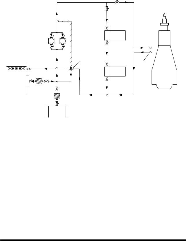
Seawater Cooling System
3EAWATER PUMPS
4HERMOSTATIC
VALVE
3EAWATER OUTLET
3EAWATER INLET
3EAWATER INLET
The letters refer to list of ‘Counterflanges’
Fig. 12.02.01: Seawater cooling system
The seawater cooling system is used for cooling, the main engine lubricating oil cooler, the jacket water cooler and the scavenge air cooler, see Fig. 12.02.01.
The lubricating oil cooler for a PTO step up gear should be connected in parallel with the other coolers. The capacity of the seawater pump is based on the outlet temperature of the seawater being maximum 50 °C after passing through the coolers – with an inlet temperature of maximum 32 °C (tropical conditions), i.e. a maximum temperature increase of 18 °C.
The valves located in the system fitted to adjust the distribution of cooling water flow are to be provided with graduated scales.
,UBRICATING
OILæCOOLER
.
 0
0
3CAVENGE
AIRæCOOLER
*ACKETæWATER COOLER
198 98 13 2.5
The inter related positioning of the coolers in the system serves to achieve:
•The lowest possible cooling water inlet temperature to the lubricating oil cooler in order to obtain the cheapest cooler. On the other hand, in order to prevent the lubricating oil from stiffening in cold services, the inlet cooling water temperature should not be lower than 10 °C
•The lowest possible cooling water inlet temperature to the scavenge air cooler, in order to keep the fuel oil consumption as low as possible.
MAN B&W MC/MC C, ME/ME-B/ME C/ME GI engines
MAN Diesel |
198 38 93 6.4 |
|
MAN B&W |
12.03 |
|
|
|
Page of 1 |
Seawater Cooling Pipes
|
04ææ |
|
|
ææ)ææ!(ææ!, |
|
|
|
4)ææ |
|
|
|
|
|
|
||
|
|
|
||||||||||||||
|
|
|
|
|
|
|
|
|
|
|
|
|
|
|
|
|
0 |
|
|
0)ææ |
|
|
|
|
|
|
|
|
4%ææ |
|
ææ)ææ!( |
||
|
|
|||||||||||||||
|
|
|
|
|
|
|
|
|
|
|
|
|
|
|
|
|
.
4)ææ ç |
4)ææ ç |
4%ææ ç ææ)ææ!( |
4%ææ ç ææ)ææ!( |
3CAVENGE |
3CAVENGE |
AIRæCOOLER |
AIRæCOOLER |
!3 |
!3 |
178 50 37 5.1
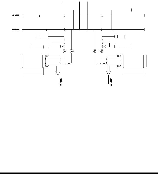
The letters refer to list of ‘Counterflanges’
The item No. refer to ‘Guidance values automation’
Fig. 12.03.01: Seawater cooling pipes for engines with two or more turbochargers
MAN B&W K108ME C6, K98MC/MC C6/7, K98ME/ME C6/7, S90MC-C7/8, S90ME C7/8, K90MC-C6, K90ME9, K90ME-C6/9
MAN Diesel |
198 39 76 4.3 |
|

MAN B&W |
12.04 |
|
|
|
Page of 1 |
Components for Seawater Cooling System
Seawater cooling pump
The pumps are to be of the centrifugal type.
Seawater flow...................... |
see ‘List of capacities’ |
Pump head.................................................... |
2.5 bar |
Test pressure...................... |
according to class rule |
Working temperature..................... |
maximum 50 °C |
The capacity must be fulfilled with a tolerance of between 0% to +10% and covers the cooling of the main engine only.
Lubricating oil cooler
See chapter 8 ‘Lubricating Oil’.
Jacket water cooler
The cooler is to be of the shell and tube or plate heat exchanger type, made of seawater resistant material.
Heat dissipation................... |
see ‘List of capacities’ |
|
Jacket water flow................. |
see ‘List of capacities’ |
|
Jacket water temperature, inlet |
......................80 °C |
|
Pressure drop |
|
|
on jacket water side..................... |
|
maximum 0.2 bar |
Seawater flow...................... |
see ‘List of capacities’ |
|
Seawater temperature, inlet |
........................... |
38 °C |
Pressure drop on |
|
|
seawater side............................... |
|
maximum 0.2 bar |
The heat dissipation and the seawater flow are based on an MCR output at tropical conditions, i.e. seawater temperature of 32 °C and an ambient air temperature of 45 °C.
Scavenge air cooler
The scavenge air cooler is an integrated part of the main engine.
Heat dissipation................... |
see ‘List of capacities’ |
|
Seawater flow ..................... |
see ’List of capacities’ |
|
Seawater temperature, |
|
|
for seawater cooling inlet, max....................... |
32 °C |
|
Pressure drop on |
|
|
cooling water side............ |
between 0.1 and 0.5 bar |
|
The heat dissipation and the seawater flow are based on an MCR output at tropical conditions, i.e. seawater temperature of 32 °C and an ambient air temperature of 45 °C.
Seawater thermostatic valve
The temperature control valve is a three way valve which can recirculate all or part of the seawater to the pump’s suction side. The sensor is to be located at the seawater inlet to the lubricating oil cooler, and the temperature level must be a minimum of +10 °C.
Seawater flow...................... |
see ‘List of capacities’ |
Temperature range, |
|
adjustable within.................................. |
+5 to +32 °C |
MAN B&W MC/MC C, ME/ME-B/ME C/ME GI engines
MAN Diesel |
198 39 81 1.3 |
|
MAN B&W |
12.05 |
|
|
Page of 1
Jacket Cooling Water System
|
|
|
|
|
|
(IGHæLEVELæALARM |
|
|
6ENTINGæPIPEæORæAUTOMATIC |
|
!LARMæMUSTæBEæGIVENæIFæEXCESSæAIR |
%XPANSIONæTANK |
|
||||
VENTINGæVALVEæTOæBEæARRANGED |
|
ISæSEPARATEDæFROMæTHEæWATERæINæTHE |
|
|||||
INæONEæENDæOFæDISCHARGEæPIPE |
|
DEAERATINGæTANK |
|
|
|
|
||
/PPOSITEæENDæOFæDISCHARGE |
|
|
|
|
|
|
||
TOæPUMP |
|
|
|
|
|
,OWæLEVELæALARM |
|
|
|
|
|
|
|
,3ææ ææ!, |
|
|
|
|
|
|
|
/RIFICEæFORæADJUSTMENTæOF |
!LARMæDEVICEæBOX |
.ORMALLYæCLOSEDæVALVE |
||
|
|
|
|
SEEæ&IG æ |
||||
|
|
|
04ææ ææ) |
COOLINGæWATERæPRESSURE |
4OæBEæOPENEDæWHENæTHE |
|||
|
- |
, |
|
|
||||
|
|
|
|
|
|
SYSTEMæISæFILLEDæWITHæ |
||
4RACINGæOFæFUELæOIL |
|
|
|
|
|
|
|
COOLINGæWATER æ -ANUALLY |
|
|
|
|
|
|
|
ORæAUTOMATICALLY |
|
DRAINæPIPE |
|
|
|
|
|
|
|
|
|
|
|
|
|
|
|
|
|
|
|
|
0REHEATER |
|
|
|
|
|
|
|
|
!. |
0REHEATERæPUMP |
|
2EGULATINGæVALVE |
|
|
!& |
|
|
|
|
|
|
||
|
|
|
|
|
4) |
|
||
|
|
|
|
|
|
|
||
æ"$ |
!( |
|
|
|
|
|
|
|
|
|
0) |
|
|
|
|
||
|
+ |
|
|
|
|
|
|
|
|
|
|
|
|
4) |
4) |
|
|
|
|
|
|
|
|
|
||
!% |
!% |
|
0) |
|
æ |
|
|
|
|
|
|
|
$EAERATINGæTANK |
|
|
||
|
|
|
|
|
&RESHWATER |
|
||
|
|
|
|
|
*ACKETæWATER |
|
||
|
|
|
|
*ACKETæWATERæPUMPS |
SEEæ&IG æ |
|
||
|
|
|
|
COOLER |
GENERATOR |
|
||
|
|
|
|
æBARæHEAD |
|
|
||
|
-AIN |
|
|
|
|
|
|
|
|
|
|
|
|
|
|
|
|
|
ENGINE |
|
|
&ROMæTRACINGæOFæFUELæOILæDRAINæPIPEææ |
|
|
||
|
|
|
7ATERæINLETæFOR |
|
|
|||
|
|
|
|
|
|
|
||
|
|
|
CLEANINGæTURBOCHARGER |
|
|
|
|
|
$RAINæFROMæBEDPLATE CLEANING |
|
|
|
|
|
|
||
TURBOCHARGERæTOæWASTEæTANK |
&RESHæCOOLINGæWATERæDRAIN |
|
|
|
|
|||
*ACKETæCOOLINGæWATER |
|
|
æ&LANGEæ"$æANDæTHEæTRACINGæLINEæAREæNOTæAPPLICABLEæONæ-#æENGINESæTYPEæ æANDæSMALLER |
|||||
3EAæWATER |
|
|
|
|
|
|
|
|
&UELæOIL |
|
|
|
|
|
|
|
|
4HEæLETTERSæREFERæTOæLISTæOFæ@#OUNTERFLANGES æ&IG æ |
|
|
|
|
||||
|
|
|
|
|
|
|
|
178 50 17 2.3 |
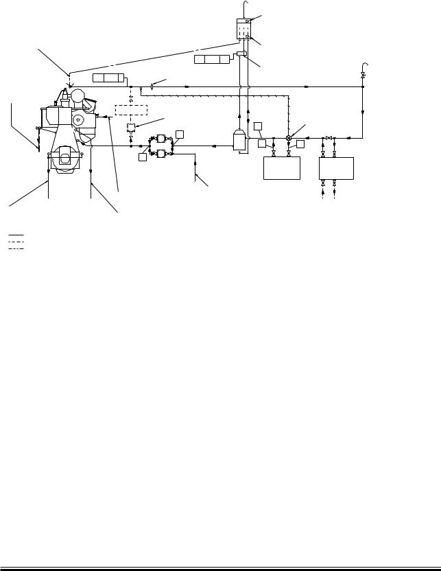
Fig. 12.05.01: Jacket cooling water system
The jacket cooling water system is used for cooling the cylinder liners, cylinder covers and exhaust valves of the main engine and heating of the fuel oil drain pipes, see Fig. 12.05.01.
The jacket water pump) draws water from the jacket water cooler outlet and delivers it to the engine.
At the inlet to the jacket water cooler there is a thermostatically controlled regulating valve, with a sensor at the engine cooling water outlet, which keeps the main engine cooling water outlet at a temperature of 80 °C.
The engine jacket water must be carefully treated, maintained and monitored so as to avoid corrosion, corrosion fatigue, cavitation and scale formation. It is recommended to install a preheater if preheating is not available from the auxiliary engines jacket cooling water system.
The venting pipe in the expansion tank should end just below the lowest water level, and the expansion tank must be located at least 5 m above the engine cooling water outlet pipe.
The freshwater generator, if installed, may be connected to the seawater system if the generator does not have a separate cooling water pump. The generator must be coupled in and out slowly over a period of at least 3 minutes.
For external pipe connections, we prescribe the following maximum water velocities:
Jacket water................................................. |
3.0 m/s |
Seawater...................................................... |
3.0 m/s |
MAN B&W MC/MC C, ME/ME-B/ME C/ME GI engines
MAN Diesel |
198 38 94 8.5 |
|
MAN B&W |
12.06 |
|
|
|
Page of 1 |
Jacket Cooling Water Pipes
 0$3ææ ææ!,
,

 4)ææ
4)ææ
!(
+
4)ææ 
4%ææ ææ)ææ!,

 04ææ ææ)ææ!,ææ9,

 0)ææ ,OCALæOPERATIONæPANEL

 03ææ ææ: /NLYæ',
7ATERæLEVELæCHECKæVALVE |
#YL æ |
4%ææ ææ)ææ!(ææ9( |
4)ææ |
- |
+
178 50 44 6.1
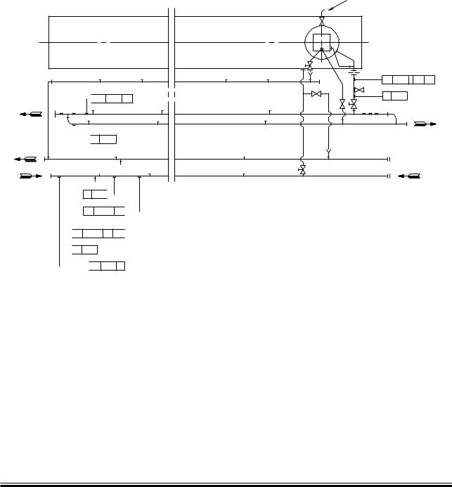
The letters refer to list of ‘Counterflanges’
The item No. refer to ‘Guidance values automation’
Fig. 12.06.01: Jacket cooling water pipes for engines with MAN Diesel turbochargers, type TCA, ABB turbochargers, type TPL, Mitsubishi turbochargers, type MET
MAN B&W S90MC-C7/8, S90ME C7/8, K90MC-C6, K90ME9, K90ME C6/9, S80MC-C7/8, S80ME C7/8/9, K80MC-C6, K80ME C6/9
MAN Diesel |
198 39 83 5.3 |
|