

книги студ / color atlas of physiology 5th ed[1]. (a. despopoulos et al, thieme 2003)
.pdf5 Respiration
108
Mechanics of Breathing
Pressure differences between the alveoli and the environment are the driving “forces” for the exchange of gases that occurs during ventilation. Alveolar pressure (PA = intrapulmonary pressure; !B) must be lower than the barometric pressure (PB) during inspiration (breathing in), and higher during expiration (breathing out). If PB is defined as zero, the alveolar pressure is negative during inspiration and positive during expiration (!B). These pressure differences are created through coordinated movement of the diaphragm and chest (thorax), resulting in an increase in lung volume (Vpulm) during inspiration and a decrease during expiration (!A1,2).
The inspiratory muscles consist of the diaphragm, scalene muscles, and external intercostal muscles. Their contraction lowers (flattens) the diaphragm and raises and expands the chest, thus expanding the lungs. Inspiration is therefore active. The external intercostal muscles and accessory respiratory muscles are activated for deep breathing. During expiration, the diaphragm and other inspiratory muscles relax, thereby raising the diaphragm and lowering and reducing the volume of the chest and lungs. Since this action occurs primarily due to the intrinsic elastic recoil of the lungs (!p. 116), expiration is passive at rest. In deeper breathing, active mechanisms can also play a role in expiration: the internal intercostal muscles contract, and the diaphragm is pushed upward by abdominal pressure created by the muscles of the abdominal wall.
Two adjacent ribs are bound by internal and external intercostal muscle. Counteractivity of the muscles is due to variable leverage of the upper and lower rib (!A3). The distance separating the insertion of the external intercostal muscle on the upper rib (Y) from the axis of rotation of the upper rib (X) is smaller than the distance separating the insertion of the muscles on the lower rib (Z!) and the axis of rotation of the lower rib (X!). Therefore, X!–Z! is longer and a more powerful lever than X–Y. The chest generally rises when the external intercostal muscles contract, and lowers when the opposing internal intercostal muscles contract.
To exploit the motion of the diaphragm and chest for ventilation, the lungs must be able to follow this motion without being completely attached to the diaphragm and chest. This is achieved with the aid of the pleura, a thin fluid-covered sheet of cells that invests each lung (visceral pleura), thereby separating it from the adjacent organs, which are covered by the pleura as well (parietal pleura).
In its natural state, the lung tends to shrink due to its intrinsic elasticity and alveolar surface tension (!p. 118). Since the fluid in the pleural space cannot expand, the lung sticks to the inner surface of the chest, resulting in suction (which still allows tangential movement of the two pleural sheets). Pleural pressure (Ppl) is then negative with respect to atmospheric pressure. Ppl, also called intrapleural (Pip) or intrathoracic pressure, can be measured during breathing (dynamically) using an esophageal probe (!Ppl). The intensity of suction (negative pressure) increases when the chest expands during inspiration, and decreases during expiration (!B). Ppl usually does not become positive unless there is very forceful expiration requiring the use of expiratory muscles. The difference between the alveolar and the pleural pressure (PA - Ppl) is called transpulmonary pressure (!p. 114).
Characterization of breathing activity. The terms hyperpnea and hypopnea are used to describe abnormal increases or decreases in the depth and rate of respiratory movements. Tachypnea (too fast), bradypnea (too slow), and apnea (cessation of breathing) describe abnormal changes in the respiratory rate. The terms hyperventilation and hypoventilation imply that the volume of exhaled CO2 is larger or smaller, respectively, than the rate of CO2 production, and the arterial partial pressure of CO2 (PaCO2) decreases or rises accordingly (!p. 142). Dyspnea is used to describe difficult or labored breathing, and orthopnea occurs when breathing is difficult except in an upright position.
Despopoulos, Color Atlas of Physiology © 2003 Thieme
All rights reserved. Usage subject to terms and conditions of license.

A. Respiratory muscles |
|
|
|
||
|
Trachea |
|
|
|
|
Pleura |
|
|
|
|
|
Lung |
|
|
|
|
|
|
|
|
External |
|
Breathing |
|
Diaphragm |
|
intercostal |
|
|
|
|
muscles |
|
||
|
|
|
Internal |
|
|
|
|
|
|
of |
|
|
|
|
intercostal |
|
|
|
Expiration |
|
muscles |
|
Mechanics |
|
Inspiration |
2 |
Inspiration |
|
|
|
1 |
|
|||
|
|
Expiration |
|
||
|
|
|
|
|
|
|
Lever X‘–Z‘ > X–Y |
Rib cage rises |
|
|
5.2 |
|
|
|
Plate |
||
X |
Y |
Y‘ |
Y |
External intercostal m. |
|
|
|
Internal intercostal m. |
|
||
|
|
|
|
|
|
|
|
|
|
Y‘ |
|
X‘ |
Z |
Z‘ |
|
|
|
|
|
|
|
||
|
Lever X–Y > X‘–Z‘ |
Rib cage falls |
Z |
|
|
|
|
Z‘ |
|
||
|
3 |
|
Joint |
Rib |
|
|
|
|
Vertebra |
|
|
B. Alveolar pressure PA and pleural pressure Ppl during respiration |
|
||||
Visceral pleura Parietal pleura |
Vpulm (L) |
Inspiration |
Expiration |
|||
|
|
|||||
Lung |
Chest wall |
Respiratory volume |
0.4 |
|
|
|
|
|
|
|
|||
|
Rib |
0.2 |
|
|
||
|
|
|
|
|
||
|
Pleural space |
|
|
|
|
|
|
|
|
|
|
|
|
|
|
|
|
0 |
|
|
|
PA |
kPa |
cmH2O |
|
|
|
|
+0,2 |
|
+2 |
|
|
|
|
|
|
PA |
|
||
|
|
|
|
|
|
|
|
|
0 |
|
0 |
|
|
|
|
–0.2 |
|
–2 |
|
|
|
Ppl |
–0.4 |
|
–4 |
Ppl |
109 |
|
|
|
|
|||
|
|
–0.6 |
|
–6 |
|
|
Despopoulos, Color Atlas of Physiology © 2003 Thieme
All rights reserved. Usage subject to terms and conditions of license.

Purification of Respiratory Air
|
Inhaled foreign particles are trapped by mucus |
|
|
in the nose, throat, trachea, and bronchial tree. |
|
|
The entrapped particles are engulfed by mac- |
|
|
rophages and are driven back to the trachea by |
|
|
the cilia lining the bronchial epithelium. Cilial |
|
|
escalator: The cilia move at a rate of 5–10 s–1 |
|
|
and propel the mucus towards the mouth at a |
|
|
rate of 1 cm/min on a film of fluid secreted by |
|
|
the epithelium. Heavy smoking, mucoviscido- |
|
|
sis genetic defects can impair cilial transport. A |
|
|
volume of 10–100 mL of mucus is produced |
|
|
each day, depending on the type and frequency |
|
|
of local irritation (e.g., smoke inhalation) and |
|
|
vagal stimulation. Mucus is usually swallowed, |
|
Respiration |
and the fluid fraction is absorbed in the |
|
gastrointestinal tract. |
||
Artificial Respiration |
||
|
||
5 |
Mouth-to-mouth resuscitation is an emer- |
|
gency measure performed when someone |
||
|
||
|
stops breathing. The patient is placed flat on |
|
|
the back. While pinching the patient’s nostrils |
|
|
shut, the aid-giver places his or her mouth on |
|
|
the patient’s mouth and blows forcefully into |
|
|
the patient’s lungs (!A3). This raises the alve- |
|
|
olar pressure (!p. 108) in the patient’s lungs |
|
|
relative to the atmospheric pressure outside |
|
|
the chest and causes the lungs and chest to ex- |
|
|
pand (inspiration). The rescuer then removes |
|
|
his or her mouth to allow the patient to exhale. |
|
|
Expulsion of the air blown into the lungs (ex- |
|
|
piration) occurs due to the intrinsic elastic re- |
|
|
coil of the lungs and chest (!p. 109 A2). This |
|
|
process can be accelerated by pressing down |
|
|
on the chest. The rescuer should ventilate the |
|
|
patient at a rate of about 16 min–1. The exspira- |
|
|
tory O2 fraction (!p. 107 A) of the the rescuer |
|
|
is high enough to adequately oxygenate the |
|
|
patient’s blood. The color change in the |
|
|
patient’s skin from blue (cyanosis; !p. 130) to |
|
|
pink indicates that a resuscitation attempt was |
|
|
successful. |
|
|
Mechanical ventilation. Mechanical intermittent |
|
|
positive pressure ventilation (IPPV) works on the same |
|
|
principle. This technique is used when the respiratory |
|
|
muscles are paralyzed due to disease, anesthesia, |
|
110 |
etc. The pump of the respirator drives air into the |
|
patient’s lung during inspiration (! A1). The exter- |
nal inspiratory and expiratory pathways are sepa-
rated by a valve (close to the patient’s mouth as possible) to prevent enlargement of dead space (! p. 114). Ventilation frequency, tidal volume, inspiratory flow, as well as duration of inspiration and expiration can be preselected at the respirator. The drawback of this type of ventilation is that venous return to the heart is impaired to some extent (! p. 204). Today, the standard technique of mechanical respiration is continuous positive pressure ventilation
(CPPV). In contrast to IPPV, the endexpiratory pressure is kept positive (PEEP) in CPPV. In any case, all ventilated patients should be continuously monitored (expiratory gas fraction; blood gas composition, etc.).
The iron lung (Drinker respirator) makes use of negative-pressure respiration (!A2). The patient’s body is enclosed from the neck down in a metal tank. To achieve inhalation, pressure in the tank is decreased to a level below ambient pressure and, thus, below alveolar pressure. This pressure difference causes the chest to expand (inspiratory phase), and the cessation of negative pressure in the tank allows the patient to breathe out (expiratory phase). This type of respirator is used to ventilate patients who require long-term mechanical ventilation due to paralytic diseases, such as polio.
Pneumothorax
Pneumothorax occurs when air enters the pleural space and Ppl falls to zero (!p. 108), which can lead to collapse of the affected lung due to elastic recoil and respiratory failure ( !B). The contralateral lung is also impaired because a portion of the inspired air travels back and forth between the healthy and collapsed lung and is not available for gas exchange. Closed pneumothorax, i.e., the leakage of air from the alveolar space into the pleural space, can occur spontaneously (e.g., lung rupture due to bullous emphysema) or due to lung injury (e.g., during mechanical ventilation = barotrauma; !p. 134). Open pneumothorax (!B2) can be caused by an open chest wound or blunt chest trauma (e.g., penetration of the pleura by a broken rib). Valvular pneumothorax (!B3) is a life-threatening form of pneumothorax that occurs when air enters the pleural space with every breath and can no longer be expelled. A flap of acts like a valve. Positive pressure develops in the pleural space on the affected side, as well as in the rest of the thoracic cavity. Since the tidal volume increases due to hypoxia, high pressure levels (4 kPa = 30 mmHg) quickly develop. This leads to increasing impairment of cardiac filling and compression of the healthy contralateral lung. Treatment of valvular pneumothorax consists of slow drainage of excess pressure and measures to prevent further valvular action.
Despopoulos, Color Atlas of Physiology © 2003 Thieme
All rights reserved. Usage subject to terms and conditions of license.

A. Artificial respiration
Fresh air
Valves
 O2 if needed

 Expiration
Pump
1 Positive-pressure respiration
Pump
Negative pressure
Normal pressure
Negative-pressure tank (iron lung)
2 Negative-pressure respiration
3 Mouth-to-mouth resuscitation
Pressure
Inspiration
Expiration
Gas flow
 Inspiration
 Expiration
Plate 5.3 Artificial Respiration, Pneumothorax
B. Pneumothorax |
|
|
|
2 Open pneumothorax |
|
|
|
Perforated tissue |
|
|
|
acts as valve |
|
|
|
1 Normal |
|
|
|
|
Life-threatening |
111 |
|
3 Valvular pneumothorax |
complication |
||
|
|||
|
|
Despopoulos, Color Atlas of Physiology © 2003 Thieme
All rights reserved. Usage subject to terms and conditions of license.

5 Respiration
112
Lung Volumes and their Measurement
At the end of normal quiet expiration, the lung–chest system returns to its intrinsic resting position. About 0.5 L of air is taken in with each breath during normal quiet respiration; this is called the resting tidal volume (VT). Inspiration can be increased by another 3 L or so on forced (maximum) inspiration; this is called the inspiratory reserve volume (IRV). Likewise, expiration can be increased by about 1.7 L more on forced (maximum) expiration. This is called the expiratory reserve volume
(ERV). These reserve volumes are used during strenuous physical exercise (!p. 74) and in other situations where normal tidal volumes are insufficient. Even after forced expiration, about 1.3 L of air remains in the lungs; this is called the residual volume (RV). Lung capacities are sums of the individual lung volumes. The vital capacity (VC) is the maximum volume of air that can be moved in and out in a single breath. Therefore, VC = VT + IRV + ERV. The average 20-year-old male with a height of 1.80 m has a VC of about 5.3 L. Vital capacity decreases and residual volume increases with age (1.5 ! 3 L). The total lung capacity is the sum of VC and RV—normally 6 to 7 L. The functional residual capacity is the sum of ERV and RV (!A and p. 114). The inspiratory capacity is the sum of VT and IRV. All numerical values of these volumes apply under body temperature–pressure saturation (BTPS) conditions (see below).
Spirometry. These lung volumes and capacities (except FRC, RV) can be measured by routine spirometry. The spirometer (!A) consists usually of a water-filled tank with a bellshaped floating device. A tube connects the air space within the spirometer (!A) with the airways of the test subject. A counterweight is placed on the bell. The position of the bell indicates how much air is in the spirometer and is calibrated in volume units (LATPS; see below). The bell on the spirometer rises when the test subject blows into the device (expiration), and falls during inspiration (!A).
If the spirometer is equipped with a recording device (spirograph), it can be also used for graphic measurement. of the total ventilation per unit time (VE; !pp. 106 and 118),
.
compliance (!p. 116), O2 consumption (VO2), and in dynamic lung function tests (!p. 118).
Range of normal variation. Lung volumes and capacities vary greatly according to age, height, physical constitution, sex, and degree of physical fitness. The range of normal variation of VC, for example, is 2.5 to 7 L. Empirical formulas were therefore developed to create normative values for better interpretation of lung function tests. For instance, the following formulas are used to calculate the range of normal values for VC in Caucasians:
Men: VC ! 5.2 h –0.022a –3.6 (" 0.58) Women: VC ! 5.2 h – 0.018a – 4.36 (" 0.42),
where h = height (in meters) and a = age (in years); the standard deviation is given in parentheses. Because of the broad range of normal variation, patients with mild pulmonary disease may go undetected. Patients with lung disease should ideally be monitored by recording baseline values and observing changes over the course of time.
Conversion of respiratory volumes. The volume, V, of a gas (in L or m3; 1 m3 = 1000 L) can be obtained from the amount, M, of the gas (in mol), absolute temperature, T (in K), and total pressure, P (in Pa), using the ideal gas equation:
V ! M R T/P, [5.2] where P is barometric pressure (PB) minus water partial pressure (PH2O; !p. 106) and R is the universal gas constant = 8.31 J K– 1 mol-1.
Volume conditions
STPD: Standard temperature pressure dry (273 K, 101 kPa, PH2O = 0)
ATPS: Ambient temperature pressure H2O-saturated
(Tamb, PB, PH2O at TAmb)
BTPS: Body temperature pressure-saturated (310 K, PB, PH2O = 6.25 kPa)
It follows that:
VSTPD ! M R 273/101000 [m3]
VATPS ! M R TAmb/(PB – PH2O) [m3] VBTPS ! M R 310/(PB – 6250) [m3].
Conversion factors are derived from the respective quotients (M R is a reducing factor). Example: VBTPS/
VSTPD = 1.17. If VATPS is measured by spirometry at room temperature (TAmb = 20 #C; PH2Osat = 2.3 kPa) and PB = 101 kPa, VBTPS !1.1 VATPS and VSTPD !0.9
VATPS.
Despopoulos, Color Atlas of Physiology © 2003 Thieme
All rights reserved. Usage subject to terms and conditions of license.

A. Lung volumes and their measurement
|
Water |
Residual volume |
Spirometer |
|
Functional residual capacity (FRC)
Vital capacity |
|
Total lung capacity |
Paper feed |
|
|
|
|
Maximum |
|
|
|
|
|
inspiration |
+3 |
|
|
|
Inspiratory |
|
|
) |
|
|
reserve volume |
|
+2 |
BTPS |
|
|
(ca. 3L) |
|
|
(L |
|
|
|
Normal |
+1 |
volume |
|
|
|
inspiration |
Lung |
|
capacitylung |
capacity |
|
|
||
Tidal volume |
value |
|
|||
|
|
(ca. 0.5L) |
|
0 |
|
|
|
|
|
|
|
|
|
|
Baseline (resting) |
|
|
Total |
Vital FRC |
Expiratory |
|
|
|
reserve volume |
|
–1 |
|
||
|
|
(ca. 1.7L) |
Maximum |
|
|
|
|
|
|
|
|
|
|
|
expiration |
|
|
|
|
|
|
–2 |
|
|
|
Residual volume (ca. 1.3L) (not measurable by spirometry) |
|
|
|
|
|
|
|
–3 |
|
Plate 5.4 Lung Volumes and their Measurement
113
Despopoulos, Color Atlas of Physiology © 2003 Thieme
All rights reserved. Usage subject to terms and conditions of license.

5 Respiration
Dead Space, Residual Volume, Airway
Resistance
The exchange of gases in the respiratory tract occurs in the alveoli. Only a portion of the tidal volume (VT) reaches the alveoli; this is known as the alveolar part (VA). The rest goes to dead space (not involved in gas exchange) and is therefore called dead space volume (VD). The oral, nasal, and pharyngeal cavities plus the trachea and bronchi are jointly known as physiological dead space or conducting zone of the airways. The physiological dead space (ca. 0.15 L) is approximately equal to the functional dead space, which becomes larger than physiological dead space when the exchange of gases fails to take place in a portion of the alveoli (!p. 120). The functions of dead space are to conduct incoming air to the alveoli and to purify (!p. 110), humidify, and warm inspired ambient air. Dead space is also an element of the vocal organ (!p. 370).
The Bohr equation (!A) can be used to estimate the dead space.
Derivation: The expired tidal volume VT is equal to the sum of its alveolar part VA plus dead space VD (!A, top). Each of these three variables has a characteris-
tic CO2 fraction (!p. 376): FECO2 in VT, FACO2 in VA, and FICO2 in VD. FICO2 is extremely small and therefore
negligible. The product of each of the three volumes and its corresponding CO2 fraction gives the volume of CO2 for each. The CO2 volume in the expired air (VT ! FECO2) equals the sum of the CO2 volumes in its two components, i.e. in VA and VD (!A).
Thus, three values must be known to determine
the dead space: VT, FECO2 and FACO2. VT can be measured using a spirometer, and FECO2 and FACO2 can
be measured using a Bunte glass burette or an infrared absorption spectrometer. FACO2 is present in the last expired portion of VT—i.e., in alveolar gas. This value can be measured using a Rahn valve or similar device.
The functional residual capacity (FRC) is the amount of air remaining in the lungs at the end of normal quiet expiration, and the residual volume (RV) is the amount present after forced maximum expiration (!p. 112). About 0.35 L of air (VA) reaches the alveolar space with each breath during normal quiet respiration. Therefore, only about 12% of the 3 L total FRC is renewed at rest. The composition of gases in the
114 alveolar space therefore remains relatively constant.
Measurement of FRC and RV cannot be per-
formed by spirometry. This must be done using
Despopoulos, Color Atlas of Physiology © 2003 Thieme
All rights reserved. Usage subject to terms and conditions of license.

A. Measurement of dead space |
|
|
|
|
|
Resist. |
|
|
Alveolar part |
|
|
|
Tidal |
||
|
of tidal |
Dead space |
|
||||
|
volume |
Mixing |
volume |
||||
|
Airway |
||||||
|
VA |
|
volume |
|
VT |
||
|
|
|
|
VD |
|
|
|
|
FACO2 |
|
|
FICO2 |
|
FECO2 |
|
|
|
|
|
Volume, |
|||
|
Alveolar CO2 |
+ |
Dead space |
= |
CO2 volume |
||
|
Residual |
||||||
|
volume |
|
|
CO2 volume |
|
in expired air |
|
|
VA · FACO2 + VD ·FICO2 |
= |
VT · FECO2 |
||||
|
Space, |
||||||
|
|
|
|
|
|
|
|
|
VA =VT –VD |
|
FICO2=0 |
|
Insert values |
Dead |
|
Bohr equation |
|
|
|
Using normal values: |
|
0.5 (0.056 – 0.040) |
5.5 |
Dead space VD = |
VT (FACO2 – FECO2) |
|
|
VD = |
Plate |
||
FACO2 |
|
|
Dead space VD = |
0.056 |
|||
|
|
|
143 mL |
|
|||
B. Measurement of residual volume and functional residual capacity
VSp |
|
FHe0 |
FHeX |
VL |
Mixing |
|
|
|
||
|
|
|
|
|
|
|
Helium volume |
= |
|
|
Helium volumen |
|
|
|
|
(in lung and |
|
|||
(in spirometer only) |
|
|
|
|||
|
|
|
|
spirometer) |
|
|
|
|
|
|
|
|
|
VSp · FHe0 |
= |
|
|
(VSp+VL)·FHeX |
|
|
|
|
|
|
|
|
|
|
VL = VSp . |
FHe0 – FHeX |
|
VSp and FHe0 are known |
|
115 |
|
FHeX |
|
FHeX: Measurement |
|
||
|
|
|
|
|||
Despopoulos, Color Atlas of Physiology © 2003 Thieme
All rights reserved. Usage subject to terms and conditions of license.

Pressure–Volume Curve, Respiratory
Work
|
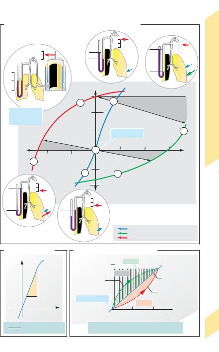
Resting position (RP) is the position to which |
||
|
the lung—chest system returns at the end of |
||
|
normal quiet expiration; this lung volume |
||
|
equals the functional residual capacity (FRC, |
||
|
!p. 114). Its value is set at zero (Vpulm = 0) in |
||
|
A–C. RP (!A1) is a stable central position |
||
|
characterized by the reciprocal cancellation of |
||
|
two passive forces: chest expansion force (CEF) |
||
|
and lung contraction force (LCF). As we |
||
|
breathe in and out, the lung – chest system |
||
|
makes excursions from resting position; thus, |
||
|
LCF ! CEF during inspiration, and CEF ! LCF |
||
|
during expiration. The difference between LCF |
||
|
and CEF, i.e. the net force (!blue arrows in A2, |
||
Respiration |
3, 5, 6), is equal to the alveolar pressure (PA |
||
!p. 108) if the airway is closed (e.g., by turn- |
|||
|
|||
|
ing a stopcock, as in A1–3, 5, 6) after a known |
||
|
air volume has been inhaled (Vpulm !0, !A2) |
||
5 |
from a spirometer or expelled into it (Vpulm "0, |
||
!A3). (In the resting position, CEF = LCF, and |
|||
|
PA = 0). Therefore, the relationship between |
||
|
Vpulm and PA in the lung—chest system can be |
||
|
determined as illustrated by the static resting |
||
|
pressure—volume (PV) curve (!blue curve |
||
|
in A–C) (“static” = measured while holding the |
||
|
breath; “resting” = with the respiratory |
||
|
muscles relaxed). |
|
|
|
(Compression and expansion of Vpulm by a positive or |
||
|
negative PA during measurement has to be taken |
||
|
into account; !A, dark-gray areas). |
||
|
The slope of the static resting PV curve, Vpulm/ |
||
|
PA, represents the (static) compliance of the |
||
|
lung–chest system (!B). The steepest part of |
||
|
the curve (range of greatest compliance; ca. |
||
|
1 L/kPa in an adult) lies between RP and Vpulm = |
||
|
1 L. This is in the normal respiratory range. The |
||
|
curve loses its steepness, i.e. compliance |
||
|
decreases, in old age or in the presence of lung |
||
|
disease. As a result, greater effort is needed to |
||
|
breathe the same tidal volume. |
||
|
The above statements apply to lung-and-chest com- |
||
|
pliance. It is also possible to calculate compliance for |
||
|
the chest wall alone ( |
VA/ Ppl = 2 L/kPa) or for the |
|
|
lung alone ( V/ [PA |
– Ppl] = 2 L/kPa) when the |
|
|
pleural pressure (Ppl) is known (!p. 108). |
|
116 |
PV relationships can also be plotted during |
|
maximum expiratory and inspiratory effort to |
||
|
determine the peak expiratory and inspiratory pressures (!A, red and green curves). Only a very small pressure can be generated from a position of near-maximum expiration (Vpulm # 0; !A7) compared to a peak pressure of about
15 kPa (!110 mmHg) at Vpulm $0 (Valsalva’s maneuver; !A5). Likewise, the greatest
negative pressure (suction) (ca. – 10 kPa = 75 mmHg) can be generated from a position of maximum expiration (Müller’s maneuver; !A6), but not from an inspiratory position (!A4).
A dynamic PV curve is obtained during respiration (!C). The result is a loop consisting of the opposing inspiratory (red) and expiratory (green) curves transected by the resting curve (blue) because airway flow resistance (RL) must be overcome (mainly in the upper and middle airways) while inhaling in the one direction and exhaling in the other. The driving pressure gradients ( P) also oppose each other (inspiratory PA "0; expiratory PA !0; !p.
109 B). As in Ohm’s law, |
P = RL ! respiratory |
. |
P must increase if |
flow rate (V). Therefore, |
the bronchial tubes narrow and/or if the respiratory flow rate increases (!C).
In asthma, the airway radius (r) decreases and a very high P is needed for normal ventilation (RL !1/r4!). During exspiration, a high P decreases the transpulmonary pressure (= PA % Ppl) and thereby squeezes the airways (RL"). The high RL results in a pressure
decrease along the expiratory airway (Pairway#) until Pairway % Ppl "0. At this point, the airway will collapse. This is called dynamic airway compression, which
often results in a life-threatening vicious cycle: r# P" r## P""....
Respiratory work. The colored areas within the
loop (ARinsp and ARexp; !C) represent the inspiratory and expiratory PV work (!p. 374) exerted to over-
come flow resistance. The cross-hatched area (!C) is the work required to overcome the intrinsic elastic
force of the lungs and chest (Aelast). Inspiratory work is defined as ARinsp + Aelast. The inspiratory muscles (!p. 108) must overcome the elastic force, whereas
the same elastic force provides the (passive) driving
force for expiration at rest (sign reverses for Aelast). Thus, expiratory work is ARexp – Aelast. Expiration can also require muscle energy if ARexp becomes larger
than Aelast—e.g., during forced respiration or if RL is elevated.
Despopoulos, Color Atlas of Physiology © 2003 Thieme
All rights reserved. Usage subject to terms and conditions of license.
A. Pressure-volume relationships of the lung-chest system
|
|
|
|
|
|
|
|
|
|
|
|
|
|
|
|
|
|
|
|
|
|
|
|
|
|
|
|
|
|
|
|
|
|
|
|
|
|
Work |
|
|
|
|
|
|
|
|
|
|
|
|
|
|
|
|
|
|
|
|
0 |
|
|
|
|
|
|
|
|
|
|
|
|
|
|
|
|
Respiratory |
|
|
Volume |
|
|
|
|
|
|
|
|
|
|
|
|
|
|
|
|
|
|
|
|
|
|
|
|
|
|
|
|
|
|
|
|
|
|
|
0 |
|
|
0 |
|
|
|
|
|
|
|
|
|
|
p>0 |
|
|
|
|
|
|
|
|
|
|
|
|
|
|
|
|
|
p>>0 |
|
|
|
|||||
|
|
|
|
|
|
|
|
|
|
|
|
|
|
|
|
|
|
|
|
|
|
|
|
|
|
|
|
|
|
|
|
|
||||||
|
|
|
|
|
|
|
|
|
|
|
|
|
|
|
|
|
|
|
|
|
|
|
|
|
|
|
|
|
|
|
|
|
|
|
|
|
|
|
Pressure |
0 |
|
|
|
|
|
|
|
|
|
|
|
|
|
|
2 |
|
|
|
|
|
|
|
|
|
|
|
|
|
|
|
|
|
5 |
|
Curve, |
||
|
|
|
|
|
|
|
|
|
|
|
Vpulm (L) |
|
|
|
|
|
|
|
|
|
|
|
|
|
|
|
|
|
|
|
|
|
|
|
||||
|
|
|
|
|
|
|
|
|
|
|
|
|
|
|
|
|
|
|
|
|
|
|
|
|
|
|
|
|
|
|
|
|
|
|
|
Pressure–Volume |
||
|
|
|
|
1 |
|
|
|
|
|
|
+3 |
|
|
|
|
2 |
|
|
o l u |
m |
e |
|
|
|
|
|
|
|
|
|
|
|
|
|
||||
|
|
|
|
|
|
4 |
|
|
|
|
|
|
|
|
|
|
|
|
|
|
|
|
|
Air compression |
||||||||||||||
|
|
|
|
|
|
|
|
|
|
s |
|
|
|
|
|
v |
|
|
|
|
|
|
|
|
|
|||||||||||||
|
|
|
|
|
|
|
|
|
|
e |
|
|
|
|
|
|
|
- |
|
|
|
|
|
|
|
|
|
|
|
|
|
|
|
|
||||
|
|
|
|
|
|
|
|
|
r |
|
|
|
|
|
|
|
|
|
|
|
|
|
|
|
|
|
|
|
|
|
|
|
|
|||||
|
|
|
|
|
|
|
|
u |
|
|
|
|
|
|
|
|
e |
|
|
|
|
|
|
|
|
|
|
|
|
|
|
|
|
|
||||
|
|
|
|
|
|
|
|
s |
|
|
|
|
|
|
|
|
|
r |
|
|
|
|
|
|
|
|
|
|
|
|
|
|
|
|
|
|
||
|
Resting position |
|
|
|
|
|
|
s |
|
|
|
+2 |
|
|
|
|
u |
|
|
|
|
|
|
|
|
|
|
|
|
|
|
|
|
|
|
|||
|
|
|
|
|
|
|
e |
|
|
|
|
|
|
|
|
|
|
|
|
|
|
|
|
|
|
|
|
|
|
|
|
|
|
|||||
|
|
|
|
|
|
|
r |
|
|
|
|
|
|
s |
|
|
|
|
|
|
|
|
|
|
|
|
|
|
|
|
|
|
|
|
||||
|
|
|
|
|
|
|
|
p |
|
|
|
|
|
|
|
|
|
|
|
|
|
|
|
|
|
|
|
|
|
|
|
|
|
|
|
|||
|
Vpulm = 0 |
|
|
|
|
|
|
y |
|
|
|
|
|
|
|
s |
|
|
|
|
|
|
|
|
|
|
|
|
|
|
|
|
|
|
|
|
|
|
|
|
|
|
|
|
|
r |
|
|
|
|
|
|
|
|
|
|
|
|
|
|
|
|
|
|
|
|
|
|
|
|
|
|
|
|
|||
|
|
|
|
|
|
|
|
o |
|
|
|
|
|
|
e |
|
|
|
|
|
|
|
|
|
|
|
|
|
|
|
|
|
|
|
|
|
|
|
|
PA = 0 |
|
|
|
|
|
|
|
|
|
|
|
r |
|
|
|
|
|
|
|
|
|
|
|
|
|
|
|
|
|
|
|
|
|
|
|||
|
|
|
|
|
|
|
t |
|
|
|
|
|
|
|
|
|
|
|
|
|
|
|
|
|
|
|
|
|
|
|
|
|
|
|
||||
|
|
|
|
|
|
|
a |
|
|
|
|
|
p |
|
|
|
|
|
|
|
|
|
|
|
|
|
|
|
|
|
|
|
|
|
|
|
||
|
|
|
|
|
|
|
ir |
|
|
|
|
g |
|
|
|
|
|
|
|
|
|
|
|
|
|
|
|
|
|
|
|
|
|
|
|
|
||
|
|
|
|
|
|
|
p |
|
|
|
|
|
|
|
|
|
|
|
|
|
|
|
|
|
|
|
|
|
|
|
|
|
|
|
|
|
||
|
|
|
|
|
|
|
|
|
|
|
|
n |
|
|
|
|
|
|
|
|
|
|
|
|
|
|
|
|
|
|
|
|
|
|
|
|
||
|
|
|
|
|
|
s |
|
|
|
|
|
|
|
|
|
|
|
|
|
|
|
|
|
|
|
|
|
|
|
|
|
|
|
|
|
|||
|
|
|
|
|
n |
|
|
|
|
|
+1 |
i |
|
|
|
|
|
|
|
|
|
|
|
|
|
|
|
|
|
|
|
|
|
|
|
|
||
|
|
|
|
|
|
|
|
|
|
t |
|
|
|
|
|
|
|
|
|
|
|
|
|
|
|
|
|
|
|
|
|
|
|
5 |
|
|||
|
|
|
|
i |
|
|
|
|
|
|
|
s |
|
|
|
Resting position |
|
|
|
|
|
|
|
|
||||||||||||||
|
|
|
a |
k |
|
|
|
|
|
|
|
|
e |
|
|
|
|
|
|
|
|
|
|
|
|
|||||||||||||
|
|
e |
|
|
|
|
|
|
|
|
|
r |
|
|
|
|
|
|
|
|
|
|
|
|
|
|
|
|
|
|
|
|
|
|
|
|
5.6 |
|
|
P |
|
|
|
|
|
|
|
|
|
|
c |
|
|
|
|
|
|
|
|
|
|
|
|
|
|
|
|
|
|
|
|
|
|
|
|
||
|
|
|
|
|
|
|
|
|
|
|
|
i |
|
|
|
|
|
|
|
|
|
|
|
|
|
|
|
|
|
|
|
|
|
|
|
|
||
|
|
|
|
|
|
|
|
|
|
|
|
t |
|
|
|
|
|
|
|
|
|
|
|
|
|
|
|
|
|
|
|
|
|
|
|
|
||
|
|
|
|
|
|
|
|
|
|
|
|
|
a |
|
|
|
|
|
|
|
|
|
|
|
|
|
|
|
|
|
|
|
|
|
|
|
|
|
|
|
|
|
|
|
|
|
|
|
|
|
|
|
|
|
|
|
|
|
|
|
|
|
|
|
|
|
|
|
|
|
|
|
|
|
|
|
|
|
|
|
|
|
|
|
|
|
|
|
|
|
t |
|
|
|
|
|
|
|
|
+5 |
|
|
|
|
|
+10 |
|
|
|
|
|
+15 |
|
|
||
|
Air expansion |
|
|
|
|
S |
|
|
|
|
|
|
|
|
|
|
|
|
|
|
|
|
|
|
PA (kPa) |
Plate |
||||||||||||
|
|
|
|
1 |
|
|
|
|
|
|
|
|
|
|
|
|
|
|
|
|
|
|
|
|
|
|
|
|||||||||||
|
|
|
|
|
|
|
|
|
|
|
|
|
|
|
|
|
|
|
|
|
|
|
|
|
|
|
|
|
|
|
|
|
|
|
|
|
||
|
–10 |
|
|
|
|
–5 |
|
|
|
|
|
|
|
|
|
|
|
|
|
|
|
|
|
|
|
|
|
|
|
|
|
|
|
s |
|
|||
|
|
|
|
|
|
|
|
|
|
|
|
|
|
|
|
|
|
|
|
|
|
|
|
|
|
|
|
|
|
|
|
|
|
|||||
|
|
|
|
|
|
|
|
|
|
|
|
|
|
|
|
|
|
|
|
|
|
|
|
|
|
|
|
|
|
|
|
re |
|
|
||||
|
|
|
|
|
|
|
|
|
|
|
|
|
|
|
|
|
|
|
|
|
|
|
|
|
|
|
|
|
|
|
|
|
|
|
u |
|
|
|
|
6 |
|
|
|
|
|
|
|
|
|
|
|
|
|
|
|
|
|
|
|
|
|
|
|
|
|
|
|
|
|
|
|
|
s |
|
|
||
|
|
|
|
|
|
|
|
|
|
|
|
|
|
|
|
|
|
|
|
|
|
|
|
|
|
|
|
|
|
|
|
s |
|
|
|
|||
|
|
|
|
|
|
|
|
|
|
|
|
|
|
|
|
|
|
|
|
|
|
|
|
|
|
|
|
|
|
|
e |
|
|
|
|
|||
|
|
|
|
|
|
|
|
|
|
|
|
|
|
|
|
|
|
|
|
|
|
|
|
|
|
|
|
|
|
|
|
r |
|
|
|
|
|
|
|
|
|
|
|
|
|
|
|
|
|
|
|
|
|
|
|
|
|
|
|
|
|
|
|
|
|
|
|
|
|
p |
|
|
|
|
|
|
|
|
|
|
|
|
|
|
|
|
|
|
|
|
|
|
|
|
|
|
|
|
|
|
|
|
|
|
|
|
|
y |
|
|
|
|
|
|
|
|
|
|
|
|
|
|
|
|
|
|
|
|
|
|
|
|
|
|
|
|
|
|
|
|
|
|
|
|
|
|
r |
|
|
|
|
|
|
|
|
|
|
|
|
|
|
|
|
|
|
|
|
|
–1 |
|
|
|
|
|
|
|
|
|
|
|
|
|
|
|
o |
|
|
|
|
|
|
|
|
|
|
|
|
|
|
|
|
|
|
|
|
|
|
|
|
|
|
|
|
|
|
|
|
|
|
|
|
at |
|
|
|
|
|
|
|
|
|
||
|
|
|
|
|
|
|
|
|
|
|
|
|
|
|
|
|
|
|
|
|
|
|
|
|
|
|
ir |
|
|
|
|
|
|
|
|
|
|
|
|
|
|
|
|
|
|
|
|
|
|
3 |
|
|
|
|
|
|
|
|
7 |
|
|
|
p |
|
|
|
|
|
|
|
|
|
|
|
|||
|
|
|
|
|
|
|
|
|
|
|
|
|
|
|
|
|
|
|
|
|
|
ex |
|
|
|
|
|
|
|
|
|
|
|
|
||||
|
|
|
|
|
|
|
|
|
|
|
|
|
|
|
|
|
|
|
|
|
|
|
|
|
ak |
|
|
|
|
|
|
|
|
|
|
|
|
|
|
|
|
|
|
|
|
|
|
|
|
|
|
|
|
|
|
|
|
|
|
|
|
|
e |
|
|
|
|
|
|
|
|
|
|
|
|
|
|
|
|
|
|
|
|
|
|
|
|
|
|
|
|
|
|
|
|
|
|
|
|
|
P |
|
|
|
|
|
|
|
|
|
|
|
|
|
|
|
|
0 |
|
|
|
|
|
|
|
|
|
|
|
–2 |
|
|
|
|
|
|
|
|
|
|
|
|
|
|
|
|
|
|
|
|
|
|
|
|
|
|
|
|
|
|
|
|
|
|
|
|
|
|
|
|
|
|
|
|
|
|
|
|
|
|
|
|
|
|
|
|
|
|
|
|
|
|
|
|
p<<0 |
|
|
|
|
|
|
|
|
|
|
0 |
|
|
|
|
|
|
|
|
|
|
|
|
|
|
|
|
|
|
|
|
|
|
|
|
|
|
|
|
|
|
|
|
|
|
|
|
|
|
|
|
|
|
|
|
|
|
|
|
|
|
|
|
|
|
|
|
|
|
|
|
|
|
|
|
|
|
|
|
|
|
|
|
|
|
p<0 |
|
|
|
|
|
|
|
|
|
|
|
|
|
|
|
|
|
|
|
|
|
|
|
|
|
|
|
|
|
|
|
6 |
|
|
|
|
|
|
|
|
|
|
|
|
|
|
|
|
|
|
|
|
|
|
|
|
|
|
|
|
|
|
|
|
|
|
|
|
|
|
Passive lung and chest forces |
3 |
Maximum force of expiratory muscles |
Maximum force of inspiratory muscles |
B. Static compliance |
||
Vpulm (L) |
|
|
|
|
Vpulm |
|
|
PA |
|
|
PA (kPa) |
Vpulm |
= |
Compliance of |
PA |
lung-chest system |
|
C. Dynamic pressure-volume curve
Vpulm (L) |
AR exp |
|
+0.5 |
|
|
|
|
|
|
Aelast |
Static resting |
Expiration |
|
pressure-volume |
|
curve |
|
|
|
|
|
|
Inspiration |
Resting position |
|
AR insp |
|
|
|
0 0 |
0.2 |
0.4 (kPa) |
Driving pressure gradient (see text)
Respiratory work |
Inspiration: |
ARinsp + Aelast |
117 |
Expiration: |
ARexp – Aelast |
|
|
|
|
Despopoulos, Color Atlas of Physiology © 2003 Thieme
All rights reserved. Usage subject to terms and conditions of license.