

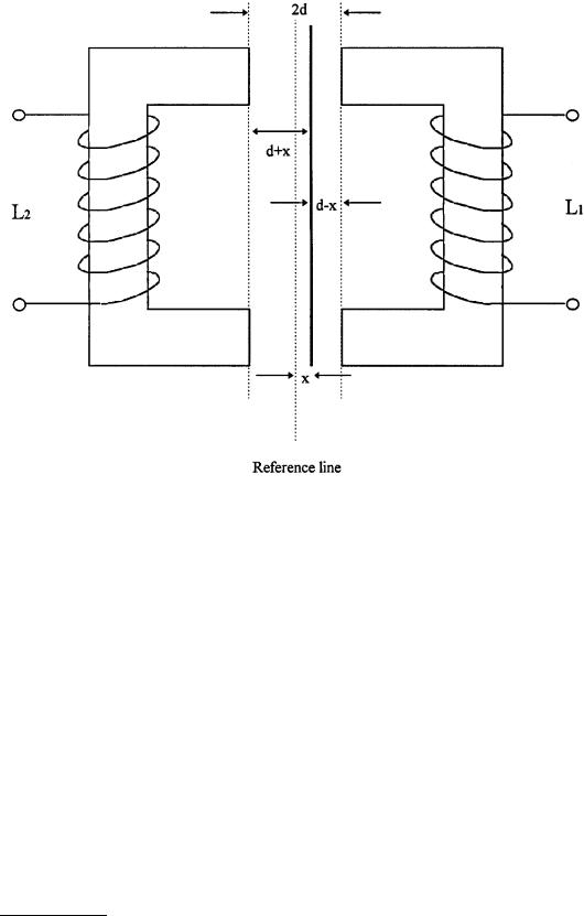
FIGURE 6.9 A variable-differential reluctance sensor consists of an armature moving between two identical cores separated by a fixed distance. The armature moves in the air gap in response to a mechanical input. This movement alters the reluctance of coils 1 and 2, thus altering their inductive properties. This arrangement overcomes the problem of nonlinearity inherent in single coil sensors.
with the principles explained above, and thereby inducing more voltage on one of the coils than on the other. Motion in the other direction reverses the action with a 180° phase shift occurring at null. The output voltage can be modified, depending on the requirements in signal processing, by means of rectification, demodulation, or filtering. In these instruments, full-scale motion may be extremely small — on the order of few thousandths of a centimeter.
In general, variable reluctance transducers have small ranges and are used in specialized applications such as pressure transducers. Magnetic forces imposed on the armature are quite large and this severely limits their application. However, the armature can be constructed as a diaphragm; hence, suitable for pressure measurements.
Variable-Reluctance Tachogenerators
Another example of a variable reluctance sensor is shown in Figure 6.11. These sensors are based on Faraday’s law of electromagnetic induction; therefore, they may also be referred to as electromagnetic sensors. Basically, the induced emf in the sensor depends on the linear or angular velocity of the motion.
The variable-reluctance tachogenerator consists of a ferromagnetic, toothed wheel attached to a rotating shaft, and a coil wound onto a permanent magnet, extended by a soft iron pole piece. The wheel moves in close proximity to the pole piece, causing the flux linked by the coil to change, thus inducing an emf in the coil. The reluctance of the circuit depends on the width of the air gap between the rotating wheel and the pole piece. When the tooth is close to the pole piece, the reluctance is minimum and it
© 1999 by CRC Press LLC
FIGURE 6.10 A typical commercial variable differential sensor. The iron core is located half-way between the two E frames. Motion of the core increases the air gap for one of the E frames while decreasing the other side. This causes reluctances to change, thus inducing more voltage on one side than the other. Motion in the other direction reverses the action, with a 180° phase shift occurring at null. The output voltage can be processed, depending on the requirements, by means of rectification, demodulation, or filtering. The full-scale motion may be extremely small, on the order of few thousandths of a centimeter.
increases as the tooth moves away from the pole. When the wheel rotates with a velocity ω, the flux may mathematically be expressed as:
Ψ(θ) = A + B cos mθ |
(6.12) |
where A = the mean flux |
|
B = the amplitude of the flux variation |
|
m = the number of teeth |
|
The induced emf is given by: |
|
E = −d Ψ(θ) dt = −(d Ψ(θ) dθ) × (dθ dt ) |
(6.13) |
or |
|
E = bmω sin mωt |
(6.14) |
© 1999 by CRC Press LLC

FIGURE 6.11 A variable-reluctance tachogenerator is a sensor which is based on Faraday’s law of electromagnetic induction. It consists of a ferromagnetic toothed wheel attached to the rotating shaft and a coil wound onto a permanent magnet extended by a soft iron pole piece. The wheel rotates in close proximity to the pole piece, thus causing the flux linked by the coil to change. The change in flux causes an output in the coil similar to a square waveform whose frequency depends on the speed of the rotation of the wheel and the number of teeth.
Both amplitude and frequency of the generated voltage at the coil are proportional to the angular velocity of the wheel. In principle, the angular velocity ω can be found from either the amplitude or the frequency of the signal. In practice, the amplitude measured may be influenced by loading effects and electrical interference. In signal processing, the frequency is the preferred option because it can be converted into digital signals easily.
The variable-reluctance tachogenerators are most suitable for measuring angular velocities. They are also used in the volume flow rate measurements and the total volume flow determination of fluids.
Microsyn
Another commonly used example of variable-reluctance transducer is the Microsyn, as illustrated in Figure 6.12. In this arrangement, the coils are connected in such a manner that at the null position of the rotary element, the voltages induced in coils 1 and 3 are balanced by voltages induced in coils 2 and 4. The motion of the rotor in the clockwise direction increases the reluctance of coils 1 and 3 while decreasing the reluctance of coils 2 and 4, thus giving a net output voltage eo. The movement in the counterclockwise direction causes a similar effect in coils 2 and 4 with a 180° phase shift. A directionsensitive output can be obtained by using phase-sensitive demodulators, as explained in LVDT section of this chapter.
Microsyn transducers are used extensively in applications involving gyroscopes. By the use of microsyns, very small motions can be detected, giving output signals as low as 0.01° of changes in angles. The sensitivity of the device can be made as high as 5 V per degree of rotation. The nonlinearity may vary from 0.5% to 1.0% full scale. The main advantage of these transducers is that the rotor does not have windings and slip-rings. The magnetic reaction torque is also negligible.
Synchros
The term synchro is associated with a family of electromechanical devices that can be discussed under different headings. They are used primarily in angle measurements and are commonly applied in control engineering as parts of servomechanisms, machine tools, antennas, etc.
The construction of synchros is similar to that of wound-rotor induction motors, as shown in Figure 6.13. The rotation of the motor changes the mutual inductance between the rotor coil and the three stator coils. The three voltage signals from these coils define the angular position of the rotor.
© 1999 by CRC Press LLC

FIGURE 6.12 A microsyn is a variable reluctance transducer that consists of a ferromagnetic rotor and a stator carrying four coils. The stator coils are connected such that at the null position, the voltages induced in coils 1 and 3 are balanced by voltages induced in coils 2 and 4. The motion of the rotor in one direction increases the reluctance of two opposite coils while decreasing the reluctance in others, resulting in a net output voltage eo. The movement in the opposite direction reverses this effect with a 180° phase shift.
Synchros are used in connection with variety of devices, including: control transformers, Scott T transformers, resolvers, phase-sensitive demodulators, analog to digital converters, etc.
In some cases, a control transformer is attached to the outputs of the stator coils such that the output of the transformer produces a resultant mmf aligned in the same direction as that of the rotor of the synchro. In other words, the synchro rotor acts as a search coil in detecting the direction of the stator field of the control transformer. When the axis of this coil is aligned with the field, the maximum voltage is supplied to the transformer.
In other cases, ac signals from the synchros are first applied to a Scott T transformer, which produces ac voltages with amplitudes proportional to the sine and cosine of the synchro shaft angle. It is also possible to use phase-sensitive demodulations to convert the output signals to make them suitable for digital signal processing.
Linear-Variable Inductor
There is a little distinction between variable-reluctance and variable-inductance transducers. Mathematically, the principles of linear-variable inductors are very similar to the variable-reluctance type of transducer. The distinction is mainly in the pickups rather than principles of operations. A typical linear variable inductor consists of a movable iron core that provides the mechanical input and two coils forming two legs of a bridge network. A typical example of such a transducer is the variable coupling transducer, which is discussed next.
© 1999 by CRC Press LLC