


FIGURE 6.96 A two-speed resolver yields two electrical cycles for one rotation.
Multispeed Units
The relationship for multispeeds is that the speed (2×, 3×, etc.) designates how many full sinusoidal cycles the resolver output electrically completes in 360° of mechanical rotation. The 2× electrical output is such that the full sinusoidal cycle for a 2× resolver occurs in 180° instead of 360°. A 2× resolver output is shown in Figure 6.96. A full 3× cycle is completed in 120°. The number of speeds selected for use is a function of the system requirements. Increasing the number of magnetic poles in the rotor and stator creates multispeed units. Each speed has several winding and slot combinations. The optimum combination is selected by the resolver designer based on system demands.
Applications
Resolvers are often used in conjunction with motors, and because of their inherent similarity of design (copper windings on iron lamination stacks), their environmental resistance is quite similar. They are ideal to design into industrial applications where dust and airborne liquids can obscure optical encoder signals. NC machines, coil winders, presses, and positioning tables are uses where resolvers excel. The resolver’s inherent resistance to shock and vibration makes it uniquely suited to moving platforms, and their reliability under these conditions lends a welcome hand to the designers of robots, gantries, and automotive transfer lines.
Heat sensitivity is always a problem for motion control systems designers. Resolvers used for sensing the position of valves in high-temperature applications such as aircraft engines, petrochemical refining, and chemical processing have continually proven their reliability.
Moving devices to precise positions with smooth and accurate control can be a real challenge in the electromagnetic noise environment of the modern industrial facility. Emitted and conducted EMI from adjacent equipment, and input voltage variations with unwanted current spikes on input power lines can rob digital systems of their signal integrity. The analog resolver continues to function without information loss or signal interruption. Digitizing the signal can be done at a remote interface under more controlled conditions than on the factory floor. Only robust materials can perform well in harsh environments.
Synchros
As long ago as World War II, synchros were used in analog positioning systems to provide data and to control the physical position of mechanical devices such as radar antennae, indicator needles on instrumentation, and fire control mechanisms in military equipment. The term “synchro” defines an electromagnetic position transducer that has a set of three phase output windings that are electrically and mechanically spaced by 120° instead of the 90° spacing found in a resolver. In the rotor primary mode, the synchro is excited by a single-phase ac signal on the rotor. As the rotor moves 360°, the three amplitude modulated sine waves on the three phases of the output have a discrete set of amplitudes for each angular position. By interpreting these amplitudes, a table can be established to decode the exact rotary position.
© 1999 by CRC Press LLC

In most applications, resolvers have replaced synchros because of the sophistication of the resolver-to- digital converters that are commercially available. Working with a sine and cosine is simpler and requires less conversion and decoding than using three 120° spaced signals. If conversion of a synchro output is desired in resolver format, a device known as a Scott “T” transformer can be used for conversion. In most synchro-to-digital processors, the first step is to convert the signal to a resolver format with a Scott “T” device.
A Modular Solution
The brushless resolver is a self-contained feedback device that, unlike optical encoders, provides an analog signal with infinite resolution. Not only can the output signal be converted to precise digital position information, but it also provides an accurate velocity signal, thus eliminating the need for using a separate tachometer. Reliability is enhanced using the same resolver for speed feedback and commutation. Piece part count can be reduced and the complexity of using Hall-effect devices for timing signals for commutation can be eliminated.
A modular approach allows the designer to easily select a single or multispeed resolver and appropriate electronics that will meet almost any desired level of resolution and accuracy. The resolvers are designed in the most commonly used frame sizes: 8, 11, 15, and 21. Housed models feature high-quality, motorgrade ball bearings. Heavy-duty industrial grade units are enclosed in rugged black painted aluminum housings with either flange, face, or servo-type mounting, and utilize MS-style connectors.
The Sensible Design Alternative for Shaft Angle Encoding
The requirement for velocity and position feedback plays an important role in today’s motion control systems. With the development of low-cost monolithic resolver-to-digital converters, a resolver-based system provides design engineers with the building blocks to handle a wide variety of applications. A resolver’s small size, rugged design, and the ability to provide a very high degree of accuracy under severe conditions, make this the ideal transducer for absolute position sensing. These devices are also well suited for use in extremely hostile environments such as continuous mechanical shock and vibration, humidity, oil mist, coolants, and solvents. Absolute position sensing vs. incremental position sensing is a necessity when working in an environment where there is the possibility of power loss. Whenever power is supplied to an absolute system, it is capable of reading its position immediately; this eliminates the need for a “go home” or reference starting point.
Resolver-to-Digital Converters
A monolithic resolver-to-digital converter requires only six external passive components to set the bandwidth and maximum tracking rate. The bandwidth controls how quickly the converter will react to a large change in position on the resolver output. The converter can also be programmed to provide either 10, 12, 14, or 16 bits of parallel data. A resolverbased system can provide high dynamic capability and high resolution for today’s motion control systems where precision feedback for both position and velocity is required.
Closed Loop Feedback
In a typical closed loop servo model as in Figure 6.97, the position sensor plays an important role by constantly updating the position and velocity information. Selection of a machine control strategy will often be based on performance, total application cost, and technology comfort. The accuracy of the system is determined by the smallest resolution of the position-sensing device. A resolver-to-digital converter in the 16-bit mode has 216 (65,536) counts per revolution, which is equivalent to a resolution of 20 arc seconds. The overall accuracy of the resolver-to-digital converter is ±2.3 arc minutes. An accuracy specification defines the maximum error in achieving a desired position. System accuracy must be smaller than the tolerance on the desired measurement. An important feature of the resolver-to-digital converter
© 1999 by CRC Press LLC

FIGURE 6.97 A closed-loop servo model uses a resolver-to-digital converter.
is repeatability. With a repeatability specification of ±1 LSB (least significant bit) in the 16-bit mode, this provides an accurate measurement when determining position from point to point. For example, moving from point A to point B and back to point A, the converter in the 16-bit mode will be accurate within 20 arc seconds of the original position. The error curve of a resolver-to-digital converter is repeatable within ±1 LSB. The combination of high precision resolvers (±20 arc seconds) with a resolver-to-digital converter provides accurate absolute position information for precision feedback for motion control.
Type II Servo Loop
The motor speed is monitored using the velocity output signal generated by the resolver-to-digital converter. This signal is a dc voltage proportional to the rate of speed, positive for increasing angles and negative for decreasing angles, with a typical linearity specification of 0.25% and a typical reversal error of 0.75%. The error processing is performed using the industry standard technique for type II tracking, resolver-to-digital converters (see Figure 6.98).
The dc error is integrated, yielding a velocity voltage that drives a voltage-controlled oscillator (VCO). This VCO is an incremental integrator (constant voltage input to position rate output) that together with the velocity integrator, forms a type II critically damped, servo feedback loop. This information allows the motor to maintain constant speeds under varying loads when it is interfaced with a programmable logic controller (PLC). The PLC-based architecture is used for I/O intensive control applications. The PLC provides a low-cost option for those developers familiar with its ladder logic programming language. Integration of the motion, I/O, operator’s interface, and communication are usually supported through additional cards that are plugged into the backplane.
Applications
Specific applications require unique profiles to control the speed and acceleration of the motor to perform the task at hand. By reducing the accelerations and decelerations that occur during each operation, it is possible to lower the cost and use more efficient motors. Industrial applications include the following:
Ballscrew positioning
Motor commutation
Robotics positioning
© 1999 by CRC Press LLC
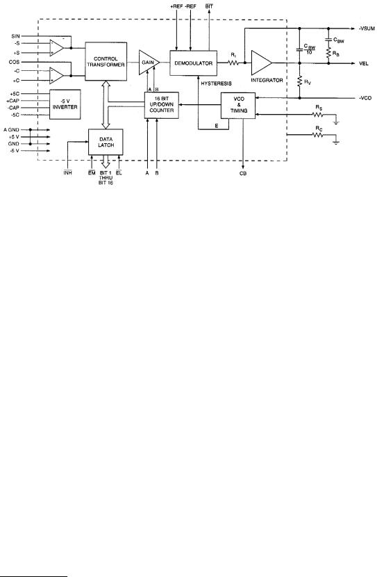
FIGURE 6.98 Error processing uses type II tracking resolver-to-digital converters.
Machine vision systems
X–Y tables
Component insertion
Remote video controls
Web guides
Pick and place machines
Resolver-to-Digital Conversion
For a resolver-to-digital converter, the resolver information is presented to a solid-state resolver conditioner that reduces the signal amplitude to 2 V rms sine and cosine; the amplitude of one being proportional to the sine of θ (the angle to be digitized), and the amplitude of the other being proportional to the cosine of θ. (The amplitudes referred to are, of course, the carrier amplitudes at the reference frequency, i.e., the cosine wave is actually cos θ cos ωt; but the carrier term, cos ωt, will be ignored in this discussion because it will be removed in the demodulator, and at any rate contains no data). A quadrant selector circuit in the control transformer enables selection of the quadrant in which θ lies, and automatically sets the polarities of the sine θ and cos θ appropriately, for computational significance. The sin θ, cos θ outputs of the quadrant selector are then fed to the sine and cosine multipliers, also contained in the control transformer. These multipliers are digitally programmed resistive networks. The transfer function of each of these networks is determined by a digital input (which switches in proportioned resistors), so that the instantaneous value of the output is the product of the instantaneous value of the analog input and the sine (or cosine) of the digitally encoded angle. If the instantaneous value of the analog input of the sine multiplier is cos θ, and the digitally encoded “word” presented to the sine multiplier is φ, then the output code is cos θ sin φ. Thus, the two outputs of the multipliers are
From the sine multiplier: cos θ sin φ
From the cosine multiplier: sin θ cos φ
These outputs are fed to an operational subtractor, at the differencing junction shown, so that the input fed to the demodulator is
sin θ cos φ – cos θ sin φ = sin (θ – φ) |
(6.114) |
© 1999 by CRC Press LLC